Electropolymerization of Starburst Triarylamines and
Their Application to Electrochromism and
Electroluminescence
Meng-Yen Chou,
†Man-kit Leung,*
,†,‡Yuhlong Oliver Su,*
,|Chang Ling Chiang,
†Chang-Chih Lin,
†Jun-Hong Liu,
†Chin-Kuei Kuo,
†and Chung-Yuan Mou
†,§Department of Chemistry, Institute of Polymer Science and Engineering, and Center for Condensed Matter Sciences, National Taiwan University, Taipei, Taiwan 106,
Republic of China, and Department of Chemistry, National Chi Nan University, Nantou, Taiwan 545, Republic of China.
Received August 7, 2003. Revised Manuscript Received December 6, 2003
Starburst triarylamines 2 and 3 were electropolymerized to form electrochromic thin films. Film from 2 showed intense absorption at 372 nm before voltage was applied. There were two absorption bands at 496 nm and 1000-2000 nm at 0.3 V, and a broad band, which peaked at 807 nm at 0.6 V. Film from 3 showed intense absorption at 372 nm before voltage was applied. There were two absorption bands at 498 nm and 1000-2000 nm at 0.3 V, and a broad band, which peaked at 890 nm at 0.7 V. The switching time studies revealed that thin film from 2 would require 3 s at 0.46 V for switching absorbance at 1600 nm and 1 s for bleaching. It would also require 4 s at 0.66 V for coloration at 800 nm and 2 s for bleaching. On the other hand, thin film from 3 would require 3 s at 0.46 V for switching absorbance at 1500 nm and 1 s for bleaching. It would also require 3.3 s at 0.76 V for switching absorbance at 900 nm and 1.5 s for bleaching. Electropolymerized thin films of 2 and 3 were also used as the surface modification layers to modify the surface of ITO for polymeric light emitting diode (PLED). To evaluate the performance of the modification layer, we selected a device of ITO/modification layer/PVK-Alq3-coumarin 6/metal electrode as the standard for comparison. We discovered that co-electropolymerization of the triarylamines 2 or 3 with poly(vinylcarbazole) (PVK) on ITO greatly reduces the turn-on voltage of the PLED devices and their performance is comparable to that of the commercially available PEDOT.
Introduction
During the last few decades, polymeric optoelectronic devices based on conjugated or nonconjugated polymers have become extremely important areas of study.1 To fabricate an optoelectronic device, the polymer is usually prepared as a uniform thin film deposited onto an ITO electrode by spin-casting or dip-coating methods. This
requires good solubility of the polymer in an appropriate solvent. Because of the low solubility of conjugated polymers, their optoelectronic applications are some-times limited. To enhance the solubility of the conju-gated polymers, alkyl or alkoxyl side chains were introduced.2 On the other hand, direct film formation on ITO glass by thermal treatment,3 self-assembly methods,4or electropolymerization4provides other op-tions to avoid the solubility problem. The family of triarylamines attracts us because of their excellent electronic properties.6Although it has long been known that triphenylamine is electrochemically active and would dimerize to give 1, compound 1 and higher linear homologues were found to be sluggish toward electro-* Authors to whom correspondence should be addressed. M.-k.L.
e-mail: mkleung@ntu.edu.tw.
†Department of Chemistry, National Taiwan University. ‡Institute of Polymer Science and Engineering, National Taiwan University.
§Center for Condensed Matter Sciences, National Taiwan Univer-sity.
|Department of Chemistry, National Chi Nan University. (1) (a) So¨nmez, G.; Schwendeman, I.; Schottland, P.; Zong, K.; Reynolds, J. R. Macromolecules 2003, 36, 639. (b) Huang, J.; Virji, S.; Weiller, B. H.; Kaner, R. B. J. Am. Chem. Soc. 2003, 125, 314. (c) Ho, H. A.; Leclerc, M. J. Am. Chem. Soc. 2003, 125, 4412. (d) Ishihara, M.; Okumoto, K.; Shirota, Y. Chem. Lett. 2003, 32, 162. (e) Okumoto, K.; Shirota, Y. Chem. Mater. 2003, 15, 699. (f) Bernier, S.; Garreau, S.; Be´ra-Abe´rem, M.; Gravel, C.; Leclerc, M. J. Am. Chem. Soc. 2002, 124, 12463. (g) Goto, H.; Yashima, E. J. Am. Chem. Soc. 2002, 124, 7943. (h) Eldo, J.; Ajayaghosh, A. Chem. Mater. 2002, 14, 410. (i) Rosseinsky D. R.; Mortimer R. J. Adv. Mater. 2001, 13, 783. (j) Liu, B.; Yu, W.-L.; Lai, Y.-H.; Huang, W. Chem. Mater. 2001, 13, 1984. (k) Kuebler, S. M.; Denning, R. G.; Anderson, H. L. J. Am. Chem. Soc.
2000, 122, 339. (l) Neef, C. J.; Brotherston, I. D.; Ferraris, J. P. Chem. Mater. 1999, 11, 1957. (m) Kraft, A.; Grimsdale, A. C.; Holmes, A. B. Angew. Chem., Int. Ed. Engl. 1998, 37, 402. (n) Monk, P. M. S.; Mortimer, R. J.; Rosseinsky, D. R. Electrochromism: Fundamentals and Applications; VCH: Weinheim, 1995.
(2) (a) Braun, D.; Heeger A. J. Appl. Phys. Lett. 1991, 58, 1982. (b) Ohmori, Y.; Uchida, M.; Muro, K.; Yoshino, K. Jpn. J. Appl. Phys. 1991, 30, L1941. (c) Grice, A. W.; Bradley, D. D. C.; Bernius, M. T.; Inbasekaran, M.; Wu, W. W.; Woo, E. P. Appl. Phys. Lett. 1998, 73, 629.
(3) Burroughes, J. H.; Bradley, D. D. C.; Brown, A. R.; Marks, R. N.; Mackay, K.; Friend, R. H.; Burns, P. L.; Holmes, A. B. Nature 1990, 347, 539.
(4) (a) Flink, S.; van Veggel, F. C. J. M.; Reinhoudt, D. N. Adv. Mater. 2000, 12, 1315. (b) Bliznyuk, V.; Ruhstaller, B.; Brock, P. J.; Scherf, U.; Carter, S. A. Adv. Mater. 1999, 11, 1257. (c) Ho, P. K. H.; Granstro¨m, M.; Friend, R. H.; Greenham, N. C. Adv. Mater. 1998, 10, 769. (d) Horowitz, G. Belannoy, P.; Bouchriha, H.; Deloffre, F.; Fave, J.-L.; Garnier, F.; Hajlaoui, R.; Heyman, M.; Kouki, F.; Valat, P.; Wintgens, V.; Yassar, A. Adv. Mater. 1994, 6, 752. (e) Geiger, F.; Stoldt, M.; Schweizer, H.; Ba¨uerle, P.; Umbach, E. Adv. Mater. 1993, 5, 922. 10.1021/cm034735p CCC: $27.50 © 2004 American Chemical Society
Published on Web 01/29/2004
Downloaded by NATIONAL TAIWAN UNIV on July 29, 2009
Results and Discussion
Synthesis and Characterization. The synthesis is shown in Schemes 1 and 2. We adopt Suzuki coupling11 as a key method for building up the 3-fold skeleton. Bromination of triphenylamine in DMF/toluene led to
4 as the core unit.12The sidearm was prepared from a
two-step synthetic sequence of Buchwald-Hartwig ami-nation,13 followed by boronic acid or ester formation. Respectively reacting 1,4-dibromobenzene and 4,4′ -dibromobiphenyl with Ph2NH in the presence of pal-ladium catalysts gave 5 and 6 in moderate yield. In the synthesis of 6, a small amount of over-amination product was obtained. Fortunately, the desired 6 was
easily purified through liquid chromatography on silica gel. Treatment of 5 with magnesium, followed by reaction with B(OMe)3 and hydrolysis led to 7. The boronic acid was then coupled with the core unit 4 to give starburst 2 as a colorless solid. By adopting a similar strategy, a higher homologue 3 was prepared from 4 and 8 in acceptable yield.
Both compounds 2 and 3 are molecular glassy materi-als with high glass-transition temperature (Tg).6,10,14 Differential scanning calorimetric analysis showed that
2 and 3 have Tg at 143 and 160 °C, respectively. In
addition, both compounds show high thermal stability, and thet have 5% weight loss temperatures at 400 and 554 °C, respectively.
The oxidative electrochemical behavior of 2 and 3 (1 mM) was examined by cyclic voltammetry (CV) on Pt electrodes in CH2Cl2 with (Bu)4NClO4 as the sup-porting electrolyte and Ag/AgCl (saturated) as the reference electrode. The potential values are reported with respect to ferrocene standard.
Starburst triarylamine 2 showed four stepwise-oxida-tion waves, which peaked at 0.25, 0.46, 0.58, and 0.7 V in the first CV scan (Figure 1a). Perhaps due to farther distances and weaker interactions between the amino units, 3 showed a shoulder at 0.34 V and a broad wave at 0.48 V in the first CV scan. As shown in the CV diagram of 3 (Figure 1b), the peak current for the first shoulder is relatively small in comparison to that of the second wave, suggesting a multistep oxidation merged in the second wave. In contrast to the linear family,9 irreversible oxidation of 2 and 3 were observed with film growing effectively on the electrode at low concentration (5) (a) Komaba, S.; Fujihana K.; Kaneko, N., Osaka, T. Chem. Lett.
1995, 10, 923. (b) Zhang, F.; Petr, A.; Kirbach, U.; Dunsch, L. J. Mater. Chem. 2003, 13, 265. (c) Roncali, J. J. Mater. Chem. 1999, 9, 1875. (d) Komaba, S.; Amano, A.; Osaka, T. J. Electroanal. Chem. 1997, 430, 97. (e) Martin, C. R. Acc. Chem. Res. 1995, 28, 61. (f) Favre, C.; Abello, L.; Delabouglise, D. Adv. Mater. 1997, 9, 722. (g) Onishi, K.; Advincula, R. C. Polym. Prepr. (Am. Chem. Soc., Div. Polym. Chem.) 2003, 44, 1167. (h) Xia, C.; Advincula, R. C. Chem. Mater. 2001, 13, 1682. (i) Onishi, K.; Advincula, R. C. Polym. Mater. Sci. Eng. 2002, 86, 259.
(6) (a) Loy, D. E.; Koene, B. E.; Thompson, M. E. Adv. Funct. Mater.
2002, 12, 245. (b) Shirota, Y. J. Mater. Chem. 2000, 10, 1. (c) Tanaka,
H.; Tokito, S.; Taga, Y.; Okada, A. Chem. Commun. 1996, 2175. (d) Adachi, C.; Nagai, K.; Tamoto, N. Appl. Phys. Lett. 1996, 66, 2679.
(7) Mizoguchi, T.; Adams, R. N. J. Am. Chem. Soc. 1962, 84, 2058. (8) (a) Lambert, C.; No¨ll, G. Synth. Met. 2003, 139, 57. (b) Petr, A.; Kvarnstro¨m, C.; Dunsch, L.; Ivaska, A. Synth. Met. 2000, 108, 245.
(9) Leung, M.-k.; Chou, M.-Y.; Su, Y. O.; Chiang, C.-L.; Chen, H.-L.; Yang, C. F., Yang, C.-C., Lin, C.-C.; Chen, H.-T. Org. Lett. 2003, 5, 839.
(10) (a) Ranasinghe, M. I.; Varnavski, O. P.; Pawlas, J.; Hauck, S. I.; Louie, J.; Hartwig, J. F.; Goodson, T., III J. Am. Chem. Soc. 2002, 124, 6520. (b) Katsuma, K.; Shirota, Y. Adv. Mater. 1998, 10, 223. (c) Kuwabara, Y.; Ogawa, H.; Inada, H.; Noma, N.; Shirota, Y. Adv. Mater.
1994, 6, 677. (d) Shirota, Y.; Kobata, T.; Noma, N. Chem. Lett. 1989,
1145. (e) Thelakkat, M.; Schmidt, H.-W. Adv. Mater. 1998, 10, 219. (11) For review, see Miyaura, N.; Suzuki, A. Chem. Rev. 1995, 95, 2457.
(12) Reynolds, D. W.; Lorenz, K. T.; Chiou, H.-S.; Bellville, D. J.; Pabon, R. A.; Bauld, N. L. J. Am. Chem. Soc. 1987, 109, 4960.
(13) (a) Hartwig, J. F. Acc. Chem. Res. 1998, 31, 852. (b) Wolfe, J. P.; Wagaw, S.; Marcoux, J.-F.; Buchwald, S. L. Acc. Chem. Res. 1998, 31, 805.
(14) (a) Tokito, S.; Tanaka, H.; Noda, K.; Okada, A.; Taga, Y. Appl. Phys. Lett. 1997, 70, 1929. (b) Tokito, S.; Tanaka, H.; Okada, A.; Taga, Y. Appl. Phys. Lett. 1996, 69, 878.
Scheme 2
Downloaded by NATIONAL TAIWAN UNIV on July 29, 2009
(1 mM). After repeated scans for film growing, the original four-wave oxidation of 2 disappeared. Instead of these, two broad oxidation waves with E1/2showed up at 0.25 and 0.45 V. These E1/2values are close to the E1/2values of 1,9 indicating the formation of the 4,4′ -diaminobiphenyl linkages. Similar observations of film growing were also obtained on oxidation of 3. Repeated scans for several cycles led to thin film of 3 with two oxidation waves, which slightly shifted to 0.3 and 0.45 V. More interesting is the fact that the first oxidation wave of 3 did not lead to electrochemical polymerization. We tentatively assigned the first wave to the oxidation of the central triarylamino core, and this resulted in an inert radical cation localized at the central part of the starburst skeleton. Further oxidation occurred at the terminal triarylamine units, which resulted in multistep oxidation and electrochemical polymerization.
Noteworthy to mention is the effect arising from the supporting electrolyte. For reasons unknown, the rate of film growth in a solution of (Bu)4NPF4is slower than the rate in a solution of (Bu)4NClO4. However, this
provides us with a good option to control the thickness of the film. In some optoelectronic applications, the film thickness of the polymer layer is important and neces-sarily controlled at around 50-100 nm.
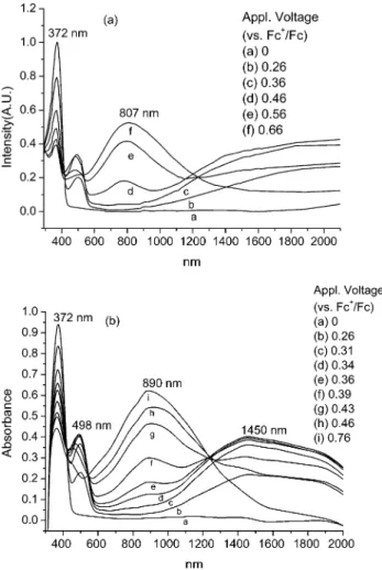
Electrochromic Properties. Electrochromism of thin films from 2 and 3 was examined by direct electrochemical deposition of the polymers onto ITO glass electrodes, and their electrochromic absorption spectra were monitored by a UV-Vis-NIR spectrom-eter at different voltages (Figure 2). The electrochemical experimental conditions were identical to those used for CV analysis. The applied voltages reported herein were referenced to the ferrocene standard. The scans for spectroelectrochemistry were made anodically, from 0.2 to 0.8 V, and there was a 2-min equilibration before each spectral scan was applied to mininize transient effect. The results are shown as a series of UV-Vis absorbance spectra correlated to film potential.
Before electrical potential was applied, the slightly yellowish polymeric films from 2 showed an intense absorption at 372 nm (Figure 2a). By setting the potential to 0.3 V, the film turnedorange and gave new absorption bands in Vis and NIR regions. They ranged from 450 to 600 and from 1000 to 2000 nm, respectively. These absorptions are tentatively attributed to the formation of the aminyl radical cations. Because of the intervalence charge transfer (IVCT) interactions with the adjacent amino groups, the aminyl radical cations usually show absorption in the NIR region. The IVCT Figure 1. Cyclic voltammogram of (a) compound 2 (1 mM),
and (b) compound 3 (1 mM) in CH2Cl2with (Bu)4NClO4(0.1 M) as the supporting electrolyte.
Figure 2. Electrochromic behavior of polymeric thin films from (a) 2, and (b) 3, at electrical potential vs Fc+/Fc as the reference in CH2Cl2with (Bu)4NClO4(0.1 M) as the supporting electrolyte.
Downloaded by NATIONAL TAIWAN UNIV on July 29, 2009
phenomenon of the family of triarylamines has been explored by many research teams.15Further increasing the applied potential to 0.6 V led to a deep blue film with a broad absorption band, which peaked at 807 nm, and covered the visible and NIR regions, which ranged from 400 to 1200 nm.
Thin films from 3 showed similar electrochromic behavior (Figure 2b). Before electrical potential was applied, the polymeric film from 3 showed intense absorption in the UV region, and peaked at 372 nm. By setting the potential to 0.3 V, the film gave new absorption bands in the Vis and NIR regions, which ranged from 450 to 600 and 1000 to 2000 nm, respec-tively. Further increasing the applied potential to 0.7 V led to a broad absorption band, which peaked at 890 nm, and covered the visible and NIR regions ranging from 400 to 1500 nm.
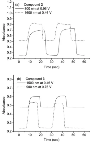
The color switching times were estimated by applying a potential step, and the absorbance profiles were followed (Figure 3). The switching time was defined as the time that required to reach 90% of the full change in absorbance after switching potential. Thin films from 2 would require 3 s at 0.46 V for switching absorbance at 1600 nm and 1 s for bleaching. When the potential was set at 0.66 V, thin films from 2 would require almost 4 s for coloration at 800 nm and 2 s for bleaching. On the other hand, thin films from 3 would require 3 s at
0.46 V for switching absorbance at 1500 nm and 1 s for bleaching. When the potential was set at 0.76 V, thin films from 3 would require 3.3 s for switching absor-bance at 900 nm and 1.5 s for bleaching.
The switching times shown above are somewhat slower than the typical switching time of 1-2 s for electrochromic polymer films. This may be due to slow ion permeation or relatively high internal resistance in comparison to those of conducting polymers such as polythiophene or polypyrrole derivatives.16 However, due to its absorption character in the NIR region, we expected that this type of electrochromic polymer would be useful for the purpose of heat absorption.
To further understand the properties of the electro-polymerized films, we selected the film from elec-trodeposition of 3 for scan rate dependent study. The cyclic voltammograms are shown in Figure 4. Scans were run at 25, 50, 75, 100, 125, 150, 175, 200, 225, and 250 mV/s, respectively. The hysteresis between the oxidative and reductive peaks increases with the scan rate, from ∆Ep) 0.017 V at 25 mV/s to ∆Ep) 0.13 V at 250 mV/s for the first wave, and from ∆Ep) 0.019 V at 25 mV/s to ∆Ep ) 0.15 V at 250 mV/s for the second wave. This increasing hysteresis indicates a non-Nerns-tian condition at the reactive front, possibly due to slow electron transfer from ITO to the polymer matrix, or more likely arising from the resistance to redox propa-gation in the polymer matrix. On the other hand, oxidation and reduction peak heights scale linearly with
(15) (a) Nelsen, S. F.; Pladziewicz, J. R. Acc. Chem. Res. 2002, 35, 247. (b) Lambert, C.; No¨ll, G. Chem. Eur. J. 2002, 8, 3467. (c) Lambert, C.; No¨ll, G. Angew. Chem., Int. Ed. 1998, 37, 2107. (d) Lambert, C.; No¨ll, G. J. Am. Chem. Soc. 1999, 121, 8434. (e) Hauck, S. I.; Lakshmi, K. V.; Hartwig, J. F. Org. Lett. 1999, 1, 2057.
(16) (a) Gaupp, C. L.; Welsh, D. M.; Rauh, R. D.; Reynolds, J. R. Chem. Mater. 2002, 14, 3964. (b) Delongchamp, D. M.; Kastantin, M.; Hammond, P. T. Chem. Mater. 2003, 15, 1575. (c) Meng, H.; Tucker, D.; Chaffins, S.; Chen, Y.; Helgeson, R.; Dunn, B.; Wudl, F. Adv. Mater.
2003, 15, 146. (d) Bach, U.; Corr,. D.; Lupo, D.; Pichot, F.; Ryan, M. Adv. Mater. 2002, 14, 845. (e) Cutler, C. A.; Bouguettaya, M.; Reynolds, J. R. Adv. Mater. 2002, 14, 684. (f) Reeves, B. D.; Thompson, B. C.; Abboud, K. A.; Smart, B. E.; Reynolds, J. R. Adv. Mater. 2002, 12, 717. (g) Somani, P. R.; Radhakrishnan, S. Mater. Chem. Phys. 2002, 77, 117. (h) Schwendeman, I.; Hickman, R.; So¨nmez, G.; Schottland, P.; Zong, K.; Welsh, D. M.; Reynolds, J. R. Chem. Mater. 2002, 14, 3118. (i) Boehme, J. L.; Mudigonda, D. S. K.; Ferraris, J. P. Chem. Mater. 2001, 13, 4469. (j) Thompson, B. C.; Schottland, P.; Zong, K.; Reynolds, J. R. Chem. Mater. 2000, 12, 1563. (k) Mudigonda, D. S. K.; Boehme, J. L.; Brotherston, I. D.; Meeker, D. L.; Ferraris, J. P. Chem. Mater. 2000, 12, 1508. (l) Gaupp, C. L.; Zong, K.; Schottland, P.; Thompson, B. C.; Thomas, C. A.; Reynolds, J. R. Macromolecules 2000, 33, 1132. (m) Welsh, D. M.; Kumar, A.; Meijer, E. W.; Reynolds, J. R. Adv. Mater. 1999, 11, 1379.
Figure 3. Potential step absorptometry of (a) the polymeric film of 2 at 800 and 1600 nm, and (b) the polymeric film of 3 at 900 and 1500 nm in CH2Cl2with (Bu)4NClO4(0.1 M) as the supporting electrolyte.
Figure 4. Scan-rate-dependent cyclic voltammograms of the thin film from electropolymerization of 3 at 25 (a), 50 (b), 75 (c), 100 (d), 125 (e), 150 (f), 175 (g), 200 (h), 225 (i), and 250 (j) mV/s in CH2Cl2with (Bu)4NClO4(0.1 M) as the supporting electrolyte. Potential vs Fc+/Fc was used as the reference.
Downloaded by NATIONAL TAIWAN UNIV on July 29, 2009
the scan rate, suggesting that the counterion diffusion in the film is reasonably fast.16b In other words, the polymer matrix formed electrochemically from 3 would be relatively porous and have an open, ion-permeable morphology.
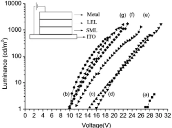
PLED Application. To evaluate the possibility and performance of using the electrochemically deposited thin film on ITO as the surface modification layer, we selected a device of ITO/modification layer/PVK-Alq3 -coumarin 6/metal electrode as a standard device struc-ture for comparison.17 Their brightness-voltage rela-tionships are shown in Figure 5.
Without any surface modification, the PLED device showed a high turn-on voltage at 27 V (line a). In contrast, the introduction of a commercially available PEDOT18as a hole-injection layer onto the ITO surface significantly reduced the turn-on voltage to 10 V (line b), indicating that the hole-injection process is one of the major factors for the device performance. On the other hand, work function of the metal electrode is less important in this case. Changing the metal electrode from Al to Mg/Ag did not further improve the turn-on voltage significantly. Electrochemical deposition of 3 as a hole-injection layer led to an improvement of the turn-on voltage to 14 V (line c). However, the surface uniformity of the electrochemically deposited thin-film is relatively poor. Although good film was obtained from electrochemical deposition of PVK,5 the improvement of the turn-on voltage to 16 V (line d) is limited by the high ionization potential of the carbazole unit. In contrast, doping of 3 into PVK by electrochemical co-deposition led to a good quality polymeric film with a thickness of 80 nm. A dramatic drop of the device turn-on voltage to 11.5 V was found (line e), using Al as the electrode. In addition, changing the metal electrode from
Al to Mg/Ag further improved the turn-on voltage to 10 V (lines f and g). The highest brightness of 2000 cd/m2 was obtained from this device. We tentatively attribute the low turn-on voltage to the lower oxidation potential of the starburst triarylamine unit, which is beneficial for the hole-injection process. Similar phenomena have been widely explored in the related PLED and OLED literature.19Although introduction of the electrochemi-cal modification layer would be beneficial for the hole injection process, we believe that it does not significantly alter the mechanism for electroluminescence. Figure 6 shows the brightness-current characteristics for the devices of ITO/PEDOT/LEL/Mg-Ag, ITO/PVK-2/LEL/ Mg-Ag, and ITO/PVK-3/LEL/Mg-Ag. All three devices provided similar brightness-current behavior, indicat-ing that similar electron-photon conversion mecha-nisms are operating in these devices. Figure 7 shows the photoluminescence spectra of PVK, PVK/Alq3, PVK/ coumarin 6, PVK/Alq3/coumarin 6, and electrolumines-cence (EL) spectrum of the device of PVK+3 SML/PVK-Alq3-coumarin 6/Mg-Ag for comparison. The emission spectrum of the EL device peaked at 500 nm with a (17) (a) Kido, J.; Hongawa, K.; Okuyama, K.; Nagai, K. Appl. Phys.
Lett. 1994, 64, 815. (b) Osaka, T.; Komaba, S.-i.; Fujihana, K.; Okamoto, N.; Kaneko, N. Chem. Lett. 1995, 1023. (c) Allegrini, M.; Arena, A.; Girlanda, R.; Pace, C.; Patane`, S.; Saitta, G. J. Mater. Res. 1999, 14, 2640.
(18) (a) Cao, Y.; Yu, G.; Zhang, C.; Menon, R.; Heeger, A. J. Synth. Met. 1997, 87, 171. (b) Brown, T. M.; Kim, J. S.; Friend, R. H.; Calcialli, F.; Daik, R.; Feast, W. J. Appl. Phys. Lett. 1999, 75, 1679. (c) Ho, P. K. H.; Kim, J.-S.; Burroughes, J. H.; Beacker, H.; Li, S. F. Y.; Brown, T. M.; Cacialli, F.; Friend, R. H. Nature (London) 2000, 404, 481.
(19) (a) Zhou, X.; Pfeiffer, M.; Blochwitz, J.; Werner, A.; Nollau, A.; Fritz, T.; Leo, K Appl. Phys. Lett. 2001, 78, 410. (b) Giebeler, C.; Antoniadis, H.; Bradley, D. D. C.; Shirota, Y. Appl. Phys. Lett. 1998, 72, 2448 (c) Giebeler, C.; Antoniadis, H.; Bradley, D. D. C.; Shirota, Y. J. Appl. Phys. 1999, 85, 608. (d) Carter, S. A.; Angelopoulos, M.; Karg, S.; Brock, P. J.; Scott, J. C. Appl. Phys. Lett. 1997, 70, 2067. (e) Yang, Y.; Heeger, A. J. Appl. Phys. Lett. 1994, 64, 1245.
Figure 5. Luminance-voltage characteristic of the light-emitting devices (a) ITO/LEL/Al, (b) ITO/PEDOT/LEL/Al, (c) ITO/3/LEL/Al, (d) ITO/PVK/LEL/Al, (e) ITO/PVK+3/LEL/Al, (f) ITO/PVK+3/LEL/Mg-Ag, and (g) ITO/PVK+2/LEL/Mg-Ag. LEL (light-emitting layer)/PVK/Alq3/Coumarin 6 ) 100: 25:0.2 (mg) in 7.6 mL of CHCl3. SML: surface modification layer. PEDOT: poly(3,4-ethylenedioxythiophene). The inset shows the structure of the devices.
Figure 6. Current and brightness characteristics of the PLED device with (9) PEDOT modification layer, (b) co-deposition of 3 and PVK modification layer, and (2) co-deposition of 2 and PVK modification layer.
Figure 7. Photoluminescence (PL) and electroluminscence (EL) on ITO glass: (a) PL of PVK; (b) PL of PVK/Alq3; (c) PL of PVK/Alq3/coumarin 6; (d) EL of the above device based on PVK+3 SML/PVK-Alq3-coumarin 6/Mg-Ag; (e) PL of PVK/ coumarin 6.
Downloaded by NATIONAL TAIWAN UNIV on July 29, 2009
shoulder at 525 nm that mainly arises from Alq3/ coumarin 6. The emission mechanisms of the Alq3/ coumarin 6 system have been discussed in previous literature.20
It has long been known that electrochemical deposi-tion of PVK would form thin film with good quality. In our study, we monitored the electrochemical co-deposi-tion process of 3 with PVK by CV and the diagrams are shown in Figure 8. The first scan showed an oxidation profile similar to that of 3, along with film growing on the electrode in repeated scans. This observation sug-gested that oxidation of 3 is important in the initiation of the co-deposition process. On the other hand, the CV profile of the final polymeric film was found to be different from either the pure thin film of 3 or that of PVK (Figure 9). The Epaand Epcof the co-deposited film are slightly shifted in comparison to those of pure film of 3 or PVK. This observation is consistent with the assumption that co-deposition occurs during electro-chemical oxidation. However, the redox behavior of the final co-deposited film is somewhat similar to that of 3 rather than that of PVK, implying that the weight of 3 in the film is significantly high. Since triarylamine derivatives are known to be effective hole-transporting materials, this layer may also function as a hole-transporting layer in the EL device.
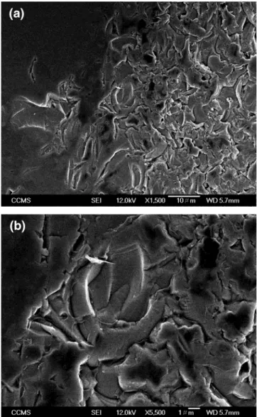
To have a physical picture of the morphology of the deposited thin film, film from electrochemical
co-deposition of 3 and PVK was subjected to scanning electron microscopy (SEM) analysis. The SEM photo-graphs are shown in Figure 10a and b. The bottom picture, Figure 10b, is an enlargement of the central area of Figure 10a. In Figure 10a, a smooth surface shown on the left represents the major part of the surface while a rough surface on the right let us clearly see the amorphous morphology of the film.
In summary, our results provided a convenient way to fabricate thin films of electroactive starburst triaryl-amine polymers. Research of this electropolymerization technique to other optoelectronic devices is ongoing.
Experimental Section
Procedures for Electropolymerization.
Electropolymer-ization of monomers 2 and 3 (1 mM) was carried out by using the CV method (0-1.5 V, 100 mV/sec) in CH2Cl2, using Bu4 -NClO4(0.1 M) or Bu4NPF6(0.1 M) as the supporting electro-lyte. The polymeric film was obtained on an ITO glass or Pt working electrode, with a Pt wire as the counter electrode, and a Ag/AgCl (saturated) electrode as the reference electrode.
Fabrication of Electrochromic Devices. An ITO glass
electrode was used as the working electrode. A layer of polymer
2 or 3 was deposited onto the ITO electrode according to the
(20) (a) Tang, C. W.; VanSlyke, S. A.; Chen, C. H. J. Appl. Phys.
1989, 65, 3610. (b) Kido, J.; Iizumi, Y. Appl. Phys. Lett. 1998, 73, 2721. Figure 8. Cyclic voltammogram of compound 3 and PVK in CH2Cl2with (Bu)4NClO4(0.1 M) as the supporting electrolyte.
Figure 9. Comparison of the final CV cycles of (a) PVK, (b) 3, and (c) a mixture of compound 3 and PVK.
Figure 10. SEM pictures of thin film from electrochemical co-deposition of 3 and PVK: (a) morphology of the surface, and (b) close-up of the central area.
Downloaded by NATIONAL TAIWAN UNIV on July 29, 2009
above procedure. After polymerization, the film obtained was washed with CH2Cl2. The electrode was then inserted into a solution of Bu4NClO4(0.2 M) in CH2Cl2. The electrochromism experiments were carried out with applied voltages from 0 to 1.3 V with respect to a Ag/AgCl (saturated) reference electrode, and their corresponding UV-Vis-NIR absorption spectra were recorded by a Jasco V-570 spectrometer.
Fabrication of PLED Devices. To fabricate the PLED, a
layer of electropolymerized film was deposited onto ITO glass (<20 Ω/sq, Merck Display Technologies Ltd., Taiwan) accord-ing to the above procedure. The concentrations of 2 and 3 used in the electropolymerization experiments were 1 mM. The thickness was 50 nm. In the co-electropolymerization experi-ment of 2 with PVK, a solution of 2 (10 mg) and PVK (5 mg) in the supporting electrolyte (10 mL) of TBAP (0.1 M) in CH2 -Cl2was used. In the co-electropolymerization experiment of 3 with PVK, a solution of 3 (12 mg) and PVK (5 mg) in the supporting electrolyte (10 mL) of TBAP (0.1 M) in CH2Cl2was used. The scan rate was 100 mV/s. The thickness was 80 nm. After electropolymerization, the film was undoped by applying a negative potential of -0.1 V, washed with CH2Cl2, and dried at 80 °C in a vacuum oven for 1 h. The light-emitting layer was spin-coated (4000 rpm, 60 s) on the electropolymeric film and dried at 130 °C for 5 min. The thickness of the emitting layer was 100 nm. Finally, a metal electrode was formed by thermal vapor deposition under vacuum (pressure less than 10-5Torr). The conductivity experiment was measured by a Keithley 2100 source meter, and the brightness was recorded by a luminance meter (Minolta LS-100). The thickness and roughness were measured by a surface finish measuring system (Kosaka Laboratory Ltd. Surfcorder 1700R).
Synthetic Procedures. Tris(4-bromophenyl)amine (4). To
an ice-cooled solution of triphenylamine (3 g, 0.012 mol, in 20 mL of toluene) was added dropwise NBS solution (6.75 g, 0.038 mol, in 60 mL of DMF). After the addition, the mixture was stirred for a further 15 min and the reaction was quenched by addition of water. The product was extracted with CH2Cl2, dried over anhydrous MgSO4, and concentrated under vacuum. The solid was first recrystallized from hexane, and then recrystallized again from CH3CN and EtOH to give 4 (2.65 g, 45%) as a white solid.1H NMR (300 MHz, CDCl
3): δ 7.33 (d,
J ) 8.8 Hz, 6H), 6.90 (d, J ) 8.8 Hz, 6H).13C NMR (100 MHz,
CDCl3): δ 146.3, 132.8, 125.9, 116.3. HRMS-FAB calcd for C18H12N79Br81Br2, 482.8479; found, 482.8474. Calcd for C18H12 -N79Br
281Br, 480.8499; found, 480.8500.
(4-Bromophenyl)diphenylamine (5). A stirred solution of
1,4-dibromobenzene (3.49 g, 14.8 mmol), diphenylamine (1.0 g, 5.9 mmol), Pd2(dba)3(245 mg, 0.2 mmol), dppf (198 mg, 0.4 mmol), and NatOBu (683 mg, 7.1 mmol) in toluene (6 mL) was heated at 90 °C under Ar atmosphere for 48 h. After that, the product solution was collected through filtration, and the remaining solid was then washed with CH2Cl2. The filtrate was collected, dried over anhydrous MgSO4, and evaporated under vacuum. The crude product was purified by chromatography on silica gel, using hexane/ethyl acetate (19:1) as the eluent to give 5 (1.4 g, 73%) as a colorless solid.1H NMR (400 MHz, CD
3 -COCD3): δ 7.40 (d, J ) 9.0 Hz, 2H), 7.31 (t, J ) 7.4 Hz, 4H), 7.07 (m, 6H), 6.94 (d, J ) 9.0 Hz, 2H).13C NMR (100 MHz, CD3COCD3): δ 147.4, 147.3, 132.1, 129.5, 124.8, 124.5, 123.5, 114.1. HRMS-FAB calcd for C18H14N81Br, 325.0289; found, 325.0291. Calcd for C18H14N79Br, 323.0310; found, 323.0317.
(4′-Bromobiphenyl-4-yl)diphenylamine (6). A stirred solution
of 4,4′-dibromobiphenyl (5.17 g, 17 mmol), diphenylamine (1.05 g, 6.2 mmol), Pd(OAc)2(33 mg, 0.15 mmol), dppf (85 mg, 0.15 mmol), and NatOBu (6.0 g, 62 mmol) in toluene (15 mL) was heated at 100 °C under Ar atmosphere for 24 h. After that, the product solution was collected through filtration, and the remaining solid was then washed with ethyl acteate. The filtrates were collected, dried over anhydrous MgSO4, and evaporated under vacuum. The crude product was purified by chromatography on silica gel, using hexanes/ethyl acetate (95: 1) as the eluent to give 6 (1.0 g, 40%) as a colorless solid.1H NMR (CDCl3): δ 7.53 (d, J ) 8.6 Hz, 2H), 7.42 (two sets of overlaying d, J ) 8.6 Hz, 4H), 7.28-7.26 (m, 4H), 7.15-7.12
(m, 6H), 7.05 (t, J ) 7.4 Hz, 2H).13C NMR (CDCl
3): δ 147.51, 139.51, 133.58, 131.78, 129.29, 128.14, 127.52, 124.51, 124.37, 123.66, 123.08, 120.87. HRMS-FAB calcd for C24H18BrN, 399.0623; found, 399.0629.
4-(Diphenylamino)phenylboronic Acid (7). To Mg turnings
(12 g, 0.5 mol) was added a small portion of 5 (2 g, 6.17 mmol) in THF (70 mL) to initiate the reaction. After initiation, an additional amount of 5 (38 g, 0.12 mol) in THF (180 mL) was added dropwise. After addition, the solution was heated at reflux for 2 h. The solution was then cooled to -78 °C and a solution of trimethylborate (28 mL, 0.37 mol) in THF (50 mL) was added. After further reaction for 12 h at room tempera-ture, the reaction was quenched by addition of diluted HCl, and the product was extracted with CH2Cl2several times. The collected organic layer was dried over anhydrous MgSO4and concentrated under vacuum to provide a crude solid which was recrystallized from CH2Cl2and CH3CN to give 7 as white solid (19.6 g, 57%), mp ) 228 °C.1H NMR (400 MHz, DMSO-d
6): δ 7.85 (s, 2H), 7.67 (d, J ) 8.4 Hz, 2H), 7.29 (t, J ) 7.6 Hz, 4H), 6.99-7.06 (m, 6H), 6.88 (d, J ) 8.4 Hz, 2H).13C NMR (100 MHz, CD3COCD3): δ 148.9, 147.0, 135.4, 129.5, 124.4, 123.3, 121.3. MS-ESI calcd for [M + H+], 290.1; found, 290.3.
Boronic Ester (8). A solution of 6 (2.05 g, 5.1 mmol) in THF
(50 mL) was stirred at -78 °C under Ar atmosphere for 10 min. A solution of n-BuLi in hexanes (5 mL, 1.6 M) was added, and the solution was stirred for 1 h. After that, 2-isopropoxy-4,4,5,5-tetramethyl-[1,3,2]-dioxaborolane21(2 mL) was added at -78 °C, and the solution was stirred for a further 16 h at room temp. When the reaction was completed, water was added to quench the reaction. The product was extracted with toluene. The collected solution was dried over anhydrous MgSO4and concentrated under vacuum to give a crude solid which was recrystallized from toluene and hexane to give 8 (2.0 g, 87%) as a colorless solid.1H NMR (400 MHz, CD 3 -COCD3): δ 7.81 (d, J ) 8.2 Hz, 2H), 7.66-7.60 (m, 4H), 7.31 (t, J ) 7.5 Hz; 4H), 7.11-7.07 (m, 8H), 1.35 (s, 12H).13C NMR (CD3COCD3): δ 148.53, 148.48, 143.83, 136.07, 135.26, 130.27, 128.56, 126.42, 125.32, 124.34, 124.08, 84.45, 25.19. HRMS-FAB calcd for C30H30O2N, 447.2370; found, 447.2373.
Starburst Amine 2. A solution of 4 (0.48 g, 1.0 mmol), 7 (0.93
g, 3.2 mmol), Pd(PPh3)4(60 mg, 0.05 mmol), and Na2CO3(0.44 g, 4.2 mmol) in toluene (1.5 mL) and H2O (1 mL) was heated at 110 °C under Ar atmosphere for 12 h. When the reaction was completed, water was added to quench the reaction. The product was extracted with CH2Cl2. The organic layer was collected, dried over anhydrous MgSO4, and evaporated under vacuum. The crude product was purified by chromatography on silica gel, using hexanes/CH2Cl2(4/1) as the eluent to give
2 (0.30 g, 31%) as a solid.1H NMR (400 MHz, CDCl 3): δ 7.49 (d, J ) 8.4 Hz, 6H), 7.47 (d, J ) 8.4 Hz, 6H), 7.27 (t, J ) 8.4 Hz, 12H), 7.21 (d, J ) 8.6 Hz, 6H), 7.15-7.13 (m, 18H), 7.03 (t, J ) 7.3 Hz, 6H).13C NMR (100 MHz, CDCl 3): δ 147.72, 146.80, 146.45, 135.07, 134.68, 129.25, 127.37, 127.31, 124.37, 124.33, 124.06, 122.84. HRMS-FAB calcd for C72H54N4, 974.4348; found, 974.4339.
Starburst Amine 3. A solution of 4 (0.68 g, 1.41 mmol), 8
(2.07 g, 4.63 mmol), Pd(PPh3)4(150 mg, 0.13 mmol), and Na2 -CO3(0.63 g, 5.9 mmol) in toluene (15 mL) and H2O (7.5 mL) was heated at 110 °C under Ar atmosphere for 24 h. When the reaction was completed, water was added to quench the reaction. The product was extracted with CHCl3. The organic layer was collected, dried over anhydrous MgSO4, and evapo-rated under vacuum. The crude product was purified by chromatography on silica gel, using hex/CH2Cl2(3:1) as the eluent to give 3 (0.72 g, 42%) as a light yellow solid.1H NMR (400 MHz, CDCl3): δ 7.66 (s, 12H), 7.59 (d, J ) 8.5 Hz, 6H), 7.55 (d, J ) 8.5 Hz, 6H), 7.32-7.26 (m, 18H), 7.18-7.16 (m, 18H), 7.06 (t, J ) 7.3 Hz, 6H).13C NMR (100 MHz, CDCl 3): δ 147.64, 147.18, 146.76, 139.07, 138.87, 135.06, 134.47, 129.27, 127.70, 127.55, 126.93, 126.92, 124.43, 123.87, 122.93. MS-FAB calcd for C90H67N4, 1203.53; found, 1203.53. Calcd for
(21) Pinacol, V.; Mehrotra, R. C.; Srivastava, G. J. Chem. Soc. 1962, 3819.
Downloaded by NATIONAL TAIWAN UNIV on July 29, 2009
Downloaded by NATIONAL TAIWAN UNIV on July 29, 2009