A Low-Makeup Beveled Tip Capillary
Electrophoresis /Electrospray Ionization Mass
Spectrometry Interface for Micellar Electrokinetic
Chromatography and Nonvolatile Buffer Capillary
Electrophoresis
Mei-Chun Tseng, Yet-Ran Chen, and Guor-Rong Her*
Department of Chemistry, National Taiwan University, Taipei, Taiwan, R.O.C
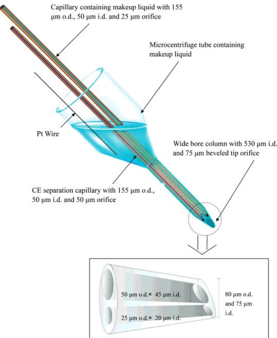
A robust interface has been developed for interfacing micellar electrokinetic chromatography (MEKC) and non-volatile buffer capillary electrophoresis (CE) to electro-spray ionization mass spectrometry (ESI-MS). The inter-face consists of two parallel capillaries for separation (50 µm i.d.× 155 µm o.d.) and makeup (50 µm i.d. × 155 µm o.d.) housed within a larger capillary (530 µm i.d.× 690 µm o.d.). The capillaries terminate in a single tapered tip having a beveled edge. The use of a tapered beveled edge results in a greater tip orifice diameter (75 µm) than in a previous design from our laboratory (25 µm) that used a flat tip. While maintaining a similar optimum flow rate and consequently similar sample dilution, a 75-µm beveled emitter is more rugged than a 25-µm flat tip. Furthermore, the incorporation of a sheath liquid capillary allows the compositions of the final spray solution to be controlled. The application of this novel CE/ESI-MS interface was demonstrated for MEKC using mixtures of triazines (positive ion mode) and phenols (negative ion mode). The ability to perform CE/ESI-MS using a non-volatile buffer was demonstrated by the analysis of gang-liosides with a buffer consisting of 40 mM borate and 20 mM r-cyclodextrin.
On-line coupling of capillary electrophosesis (CE) with elec-trospray ionization mass spectrometry (ESI-MS) is an attractive tool for direct identification of analytes because it combines excellent selectivity with structural confirmation by MS or MS/ MS. Among the techniques used to couple CE to ESI-MS, the
sheath liquid,1-3sheathless,4-13and liquid junction14-16interfaces
are the most widely used. Of these, the sheath liquid interface is the most popular because of robustness and ease of use. In addition to providing electrical contact with the outlet end of the separation capillary, a liquid sheath allows CE/ESI-MS operation
with a wide range of buffer systems.1,2However, the flow rate of
sheath liquid, in the range of several microliters per minute, is significantly higher than the flow rate of CE. Unfortunately, the associated dilution of the CE effluent ultimately reduces ESI-MS sensitivity.
In sheathless interfaces, the electrical connection to the capillary outlet is achieved by direct metal/liquid contact at or
near the tip of the CE capillary outlet.4-13Because there is no
sheath liquid to dilute the CE effluent, no dilution of the sample occurs prior to the mass spectrometer and maximum ESI sensitivity is obtained. However, the use of a single capillary in sheathless CE/ESI-MS interface causes several practical issues. For example, it is often difficult to find a solution optimized for both CE separation and ES ionization efficiency. Therefore, the selection of the CE running buffer is limited.
Given the limitations of the two interfaces, a more ideal interface would combine the versatility of the sheath liquid design with the sensitivity of the sheathless format. Recently, we developed a low-flow sheath liquid interface using a sprayer having
an orifice of reduced diameter.17A smaller spray orifice was used
because it is known that optimum flow rate decreases with orifice
* To whom correspondence should be addressed. Tel: (886) 2-23690152 ext. 109. Fax: (886) 2-23638058. E-mail:[email protected].
(1) Smith, R. D.; Barinaga, C. J.; Udseth, H. R.Anal. Chem. 1988, 60, 1948-1952.
(2) Chu, Y. H.; Dunayevskiy, Y. M.; Kirby, D. P.; Vouros, P.; Karger, B. L. J.
Am. Chem. Soc.1996, 118, 7827-7835.
(3) Nashabeh, W.; Greve, K. F.; Kirby, D.; Foret, F.; Karger, B. L.; Reifsnyder, D. H.; Builder, S. E. Anal. Chem. 1994, 66, 2148-2154.
(4) Whal, J. H.; Gale, D. C.; Smith, R. D. J. Chromatogr. 1994, 659, 217-222. (5) Kriger, M. S.; Cook, K. D.; Ramsey, R. S. Anal. Chem. 1995, 67, 385-389. (6) Moini, M. Anal. Chem. 2001, 73, 3497-3501.
(7) Chang, Y. Z.; Her, G. R. Anal. Chem. 2000, 72, 626-630.
(8) Chang, Y. Z.; Chen, Y. R.; Her, G. R. Anal. Chem. 2001, 73, 5083-5087. (9) Chen, Y. R., Her, G. R. Rapid Commun. Mass Spectrom. 2003, 17,
437-441.
(10) Wetterhall, M., Nilsson, S., Markides, K. E., Bergquist, J. Anal. Chem. 2002,
74,239-245.
(11) Petersson, M. A., Hulthe, G., Fogelqvist, E. J. Chromatogr., A 1999, 854, 141-154.
(12) Barroso, M. B., de Jong, A. P. J. Am. Soc. Mass Spectrom. 1999, 10, 1271-1278.
(13) Janini, G. M., Conrads, T. P., Wilkens, K. L., Issaq, H. J., Veenstra, T. D.Anal.
Chem.2003, 75, 1615-1619.
(14) Lee, E. D.; Muck, W.; Henion, J. D.; Covey, T. D. Biomed. Environ. Mass
Spectrom. 1989, 18, 844-850.
(15) von Brocke, A.; Nicholson, G.; Bayer, E. Electrophoresis 2001, 22, 1251-1266.
(16) Ding, J.; Vouros, P. Anal. Chem. 1999, 71, 378A-385A.
(17) Chen, Y. R.; Tseng, M. C.; Chang, Y. Z.; Her, G. R.Anal. Chem. 2003, 75, 503-508.
Anal. Chem.2004,76,6306-6312
6306 Analytical Chemistry, Vol. 76, No. 21, November 1, 2004 10.1021/ac049330i CCC: $27.50 © 2004 American Chemical Society
Downloaded by NATIONAL TAIWAN UNIV on July 31, 2009
diameter. The advantage of the smaller orifice sprayer was that it lowered the operational flow rate and thus reduced the sample dilution. Improved sensitivity of the low-flow interface was achieved when compared to a conventional sheath liquid
inter-face.17
A further advantage of a smaller orifice sprayer is that it reduces the size of the ESI droplet. Smaller droplets have a higher surface-to-volume ratio, which results in increased sensitivity and
a higher tolerance to salts in buffers.18Consequently, the
low-flow sheath liquid interface described previously provided better performance than a conventional sheath liquid interface when coupling micellar electrokinetic chromatography (MEKC) to
ESI-MS.17
Despite the success of the low-flow interface, it was found to be incompatible with the nonvolatile buffers used for CZE/ESI-MS applications. In particular, the initial flat tip design was found to be prone to clogging when used in CE/ESI-MS applications involving nonvolatile buffers.
In this paper, an improved version of the low-makeup interface is reported in which both the separation and sheath liquid capillaries are tapered and terminated in a common tip having a beveled edge. The use of a beveled tip allows the use of a tip with significantly larger orifice and thus the tip is less likely to be clogged. Another modification of the interface was the introduction of a makeup flow capillary in the interface. The use of a makeup flow column makes the final spray solution much easier to control. Successful applications are presented that demonstrate the ability of this new interface to be used with MEKC as well as conventional CE using nonvolatile buffers.
EXPERIMENTAL SECTION
Reagents. Triazine standards were obtained from Supelco (Bellefonte, PA). 2,4,-Dinitrophenol was obtained from Janssen. 4-Nitrophenol, 4-chloro-3-methylphenol, dichlorophenol, 2,4-dimethylphenol, 2-methyl-4,6-dinitrophenol (2-M-4,6-DNP), and 2,4,6-trichlorophenol were purchased from Fluka. Type III gang-liosides (GM1, GD1a, GD1b, and GT1b purified from bovine brain
containing ∼20% N-acetylneuraminic acid),
2-(N-cyclohexyl-amino)ethanesulfonic acid (CHES), and sodium dodecyl sulfate (SDS) were obtained from Sigma (St. Louis, MO). Ammonium acetate, methanol, and 2-propanol of HPLC grade were purchased from J. T. Baker (Phillipsburg, NJ) and used without further purification. R-Cyclodextrin (R-CD) was obtained from Nacalai Tesque. Hydrofluoric acid ( >48%) was obtained from Ferak Berlin. Anhydrous sodium tetraborate and ammonium hydroxide were obtained from Janssen. Deionized water (Milli-Q water system, Millipore Inc., Bedford, MA) was used in the preparation of the samples and buffer solution.
Fabrication of the Low-Flow Beveled Tip CE/ESI-MS Interface. The interface is shown in Figure 1. A beveled tapered tip was connected to a liquid reservoir (a microcentrifuge tube) and used as a sprayer for ESI. Two capillaries were inserted into the sprayer. One was used as the separation column, and the other was used to deliver a makeup flow. A syringe pump (Cole-Parmer, Vernon Hill, IL) was used to control the flow rate of the makeup flow. In this interface, the electrical contact is achieved by inserting
a platinum wire into the liquid reservoir. This electrode acts both as the electrode of the CE electric circuit and as a connection for the electrospray ionization voltage.
The beveled tapered tip was fabricated using a 530-µm-i.d. and 690-µm-o.d. capillary (Restek). The capillary was drawn manually using a vertically suspended section of capillary to which a small weight (45 g) had been attached. The capillary was slowly heated to the melting stage using a butane/oxygen microtorch (Pro-Iroda Industries Inc.) and then quickly withdrawn. A tip of 80-µm o.d. and 75-µm i.d. was obtained by removing the end of the tip using a ceramic cutter aided by visual inspection with a microscope. The tip was then wrapped with cellophane adhesive tape
and ground with a rasp to∼45°. After grinding, the tape was
removed from the tip before being connected to a microcentrifuge tube.
Preparation of the Separation and Makeup Flow Capil-laries. In this design, both the separation and makeup columns are inserted into the sprayer (Figure 1). Because the inner diameter of the emitter is 530 µm, a capillary with 155-µm o.d. was chosen as the separation as well as the makeup column. Furthermore, to minimize the dead volume between the capillaries and the sprayer, the separation and makeup columns were both tapered. To prepare the tapered capillaries, the capillaries were drawn manually using a vertically suspended section of capillary to which a small weight (10 g) had been attached. The capillaries were slowly heated to the melting stage and then quickly
withdrawn. The tapered capillaries were cut to 55 µm o.d.× 35
µm i.d. and 30 µm o.d.× 15 µm i.d. and then etched by immersing in 48% HF for 10 and 5 min, respectively. After etching, the
dimensions of capillaries were about 50 µm o.d.× 45 µm i.d. and
25 µm o.d.× 20 µm i.d.. The capillary dimension was estimated
by comparing with a 50-µm-i.d. capillary under the microscope. The capillaries were washed with deionized water to remove remaining HF. Before use, the separation capillary was conditioned with 1 M NaOH, following with 0.1 M NaOH and deionizied water. In this interface, running buffer was driven by electroosmotic flow of the capillary, whereas the flow rate of makeup liquid was controlled by a syringe pump. In addition to the flows from separation and makeup column, there was also a minor flow from the reservoir. To estimate the flow rate from the reservoir, three compounds with similar ionization efficiency (prometon, ametryn, terbutyne) were added into the running buffer, makeup column, and reservoir. The flow rate of the makeup column was controlled at 200 and 400 nL/min, respectively. Based on the relative intensity of the analytes, the flow rate from the reservoir was estimated to
be∼40 nL/min at a makeup liquid of 200 and 400 nL/min.
CE Instrument. The CE instrument was configured in-house. Briefly, the setup consisted of a 1000 R high-voltage power supply (Spellman, Plainview, NY) connected to a platinum electrode in a vial containing CE buffer and operated at constant-voltage mode. One end of the separation capillary was inserted into the CE buffer, and the other end was inserted into the CE/ESI-MS interface. In a CE/UV study, the detector (UV-C, Rainin, Emeryville, CA) wavelength was set to 200 nm.
ESI-MS. All mass spectrometry experiments were conducted on a LCQ ion trap mass spectrometer (Finnigan MAT, San Jose, CA), and the CE/ESI-MS electropherograms were acquired in selected ion monitoring mode (SIM). A commercial x-y-z
(18) Juraschek, R.; Dulcks, T.; Karas, M. J. Am. Soc. Mass Spectrom. 1999, 10, 300-308.
Downloaded by NATIONAL TAIWAN UNIV on July 31, 2009
translation stage for LCQ API source (Protana Co., Odense, Denmark) was used for mounting the low-makeup sheath liquid CE/ESI-MS interface. The position of the interface could be adjusted via the micrometer screws of the translation stage. A nebulizing gas was not necessary, and the heating capillary was
kept at a temperature of 200°C. A high-voltage power supply
(Glassman, Whitehouse Station, NJ) with 0-30-kV range, was used to apply voltage across the capillary columns.
Conventional Sheath Liquid CE/ESI-MS Interface. The CE/MS interface equipped with the LCQ ion trap mass spectrom-eter (Finnigan MAT) was used for all the sheath liquid experi-ments. The interface utilizes a triaxial flow arrangement whereby CE effluent is mixed with a suitable sheath liquid at the tip and nebulized by nitrogen gas. The sheath liquid was delivered at a flow rate of 5 µL/min by a syringe pump, and the flow rate of nebulization gas was set to 20 (an arbitrary unit).
MEKC/ESI-MS Analysis of Triazines. The MEKC running buffers contained 20 mM ammonium acetate and 25 mM SDS in water. The pH of the solution was adjusted to 7.0 with ammonia. The solution of triazine mixture (5 ppm) was hydrodynamically
injected to the capillary using a 10 mbar pressure differential for a duration of 10 s. The separation capillary was 70 cm in total length. The makeup liquid consisted of methanol, water, and acetic acid (70:30:1, v/v/v) and was injected into the liquid reservoir of the emitter and the syringe pump prior to CE/MS analysis. The mass spectrometer was operated in positive ion mode, and data were collected in SIM mode.
MEKC/ESI-MS Analysis of Phenols. The separation buffer contained 20 mM CHES and 40 mM SDS in water. The pH of the solution was adjusted to 7.0 with ammonia. The separation cap-illary was 100 cm in total length. Before each run, the capcap-illary was flushed with the separation buffer and equilibrated for 15 min. The 20 ppm phenolic mixture was hydrodynamically injected onto the capillary using a 10 mbar pressure differential for a duration of 10 s. The mass spectrometer was operated in the negative ion mode; therefore, a basic makeup liquid was required to assist negative ion formation. The makeup liquid, consisting of 2-pro-panol, water, and ammonium hydroxide (80:20;1, v/v/v), was placed into the liquid reservoir of the emitter and the syringe pump.
Figure 1. Schematic representation of the low-makeup beveled tip CE/ESI-MS interface.
Downloaded by NATIONAL TAIWAN UNIV on July 31, 2009
CZE/ESI-MS Analysis of Gangliosides Using a Nonvolatile Buffer. The separation buffer contained 40 mM borate and 20 mM R-CD in water. The pH of the solution was adjusted to 10.6 with ammonia. The separation capillary was 100 cm in total length. The type III ganglioside mixture (4 mg/mL) was hydrodynami-cally injected onto the capillary using a 10 mbar pressure differential for a duration of 10 s. The makeup liquid consisted of 2-propanol, water, and ammonium hydroxide (80:20:1, v/v/v). The mass spectrometer was operated in negative ion mode, and the data were collected in SIM mode
RESULTS AND DISCUSSION
Shape and Dimensions of the Interface. In our recently reported low-flow CE/MS interface, a tip with a 25-µm orifice was
used as the sprayer in the CE/MS interface.17Because the size
of the emitter was considerably smaller than that of a conventional
sheath liquid interface (∼400 µm), the optimum flow rate of the
emitter is significantly lower than that of a conventional sheath liquid interface. Because of reduced sample dilution resulting from a lower optimum flow rate, the sensitivity of the interface was found to be better than that obtained with a conventional sheath liquid interface.
In the current interface design, instead of using a 25-µm flat
tip,17 a 75-µm beveled tapered sprayer is used as the emitter.
Although the orifice of a 75-µm beveled tapered sprayer is significantly larger than the orifice of a 25-µm flat tip, the optimum flow rate of the two emitters is expected to be similar. In a sheathless interface, we have shown that a 75-µm beveled sprayer has anoptimum flow rate similar to that of a 25-µm flat tip (200-1000 and 200-500 nL/min for 75-µm beveled and 25-µm blunt
sprayer, respectively).8While maintaining a similar optimum flow
rate and consequently similar sample dilution, a 75-µm beveled emitter is more rugged and durable than a 25-µm flat tip because of the larger inner and outer diameters.
A second modification of the interface was the addition of a capillary to deliver makeup liquid. The flow rate of the makeup liquid was controlled by a syringe pump granting the final spray solution much easier to be controlled. Although capillary column of 360-µm o.d. is the most popular column used in CE applications, to insert two capillaries (one separation, one makeup) into the sprayer (530-µm i.d.), a column with 155-µm o.d. was chosen as the separation and the makeup capillary. Furthermore, for an interface to avoid extracolumn band broadening caused by diffusion, the dead volume between the tip of CE column and the tip of the sprayer must be kept to a minimum. To achieve
that, one end of the columns was tapered down to∼50-µm o.d.
for separation capillary and∼25 µm o.d. for makeup capillary
so that the columns could be inserted to the very end of the sprayer.
Performance of the Interface in MEKC/ESI-MS. MEKC is known for its excellent resolving power in the separation of charged as well as neutral compounds. However, the surfactants such as SDS are known to cause ionization suppression. It has been proposed that a smaller droplet has better sensitivity and
higher resistance to ionization suppression.18Although the size
of the orifice in this interface is significantly larger than that of a 25-µm flat tip, because of the similar flow rate, the diameter of the droplet produced in the interface is expected to be similar to that of a 25-µm flat tip. To evaluate the performance of the interface
in the coupling of MEKC with ESI-MS using SDS as the surfactant, a 5 ppm triazine mixture was hydrodynamically injected into the capillary using a 10 mbar pressure differential for a duration of 10 s. The MEKC running buffer was 20 mM ammonium acetate and 25 mM SDS in water at pH 7. The composition of the makeup
liquid was critical to the performance of the CZE/ESI interface.19
Thus, makeup liquids of different composition were tested for sensitivity and stability under positive ESI conditions. A 1 ppm simetryn solution was electroosmotically infused through the silica capillary and then mixed with makeup liquid at the tip of the CE probe. The best result was obtained with a solution of 70:30 methanol/water containing 1% acetic acid. To produce the best signal, the flow rate of the makeup liquid on analyte signals was also studied. The results showed that the highest signals were observed at a flow rate of 200 nL/min. The total flow rate of the
interface was∼390 nl/min (200 nL/min from makeup column,
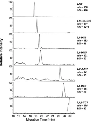
150 nL/min from separation column, and 40 nL/min from the reservoir), which was in the range of the optimum flow rate of a 75-µm beveled sprayer (200-1000 nL/min). Under the optimum conditions, the results of on-line MEKC/ESI-MS analysis of eight triazines were shown in Figure 2. Because the peak width was
(19) Foret, F.; Thompson, T. J.; Vouros, P.; Karger, B. L.; Gebauer, P.; Bocek, P. Anal. Chem. 1994, 66, 4450-4458.
Figure 2. Mass electropherograms of 5 ppm triazines using the low-makeup beveled tip interface in positive ion mode. The makeup liquid (70% methanol with 1% acetic acid) was delivered by a syringe pump at a flow rate of 200 nL/min. The potential applied to the buffer reservoir was+22 kV, and the ESI voltage was set at+2 kV.
Downloaded by NATIONAL TAIWAN UNIV on July 31, 2009
similar to the conventional interface,17no significant band boarding caused by the dead volume was observed in this interface. Although the signal/noise ratios in Figure 2 appeared to be similar to the data obtained with the previously reported low-flow flat tip
interface,17the concentration of the triazines used in this study
was 4-fold lower than that used in the low-flow interface. In the analysis of a 5 ppm triazine mixture, the average S/N ratios (n ) 3) of the 75-µm beveled and the 25-µm flat tip interfaces were 39.8 ( 13.6 and 10.4 ( 22.2%, respectively. Therefore, better sensitivity was obtained in this interface in comparison with the low-flow interface. For the 75-µm beveled interface, the LOD of
triazines was found to be∼1 ppm. One possible explanation for
the improved sensitivity is that the flow rate of the makeup liquid and thus the composition of spray solution can be controlled precisely by a syringe pump, whereas in the low-flow flat tip interface, the flow rate of the makeup liquid is uncontrolled and could be affected by the buffer composition and the potential applied to the sprayer.
The durability of the 75-µm beveled interface in MEKC-MS operation was studied by continuous infusion of a 1 ppm prometon solution (in 25 mM SDS and 20mM ammonium acetate), and the makeup liquid was supplied at 400 nL/min. The signal was found to be stable for 28 h and gradually decreased to 75% after 36 h of operation. However, for the 25-µm tapered interface, the signal was stable only for 4 h.
Under ESI-MS, the surfactant SDS gives rise to strong signals
in both positive and negative ion modes.20The ion suppression
is expected to be more serious in the negative ion mode because the anionic surfactants would occupy the surface and compete with the analytes for the excess negative charge of the droplet. In an infusion experiment, atrazine and 2-M-4,6-DNP were used to study the response under positive and negative ESI using a low-flow interface. The results showed that, at a SDS concentration
of 40 mM, the signals of the analyte dropped to∼25% in positive
ion mode and ∼8% in negative ion mode. To evaluate the
performance of this interface in negative ion MEKC, a mixture of seven phenolic compounds (20 ppm) was hydrodynamically injected into the capillary using a 10 mbar pressure differential for a duration of 10 s. The separation buffer contained 20 mM CHES and 40 mM SDS in water at pH 7. The composition of the makeup liquid was studied, and the best result was obtained with a solution of 80:20 2-propanol/water containing 1% ammonia. The effect of flow rate of the makeup liquid on the signal intensity was also studied, and the best result was obtained at a makeup
flow rate of 400 nL/min. The total flow was∼590 nL/min (400
nL/min from makeup column, 150 nL/min from separation column, and 40 nL/min from the reservoir), which was in the range of the optimum flow rate of a 75-µm beveled sprayer (200-1000 nL/min). Figure 3 shows the mass electropherograms of phenols using the low-flow beveled tip interface at a makeup flow rate of 400 nL/min. The quality of the signals was found to be better than that obtained with the recently reported low-flow flat tip interface in which four of the seven phenols were not detected (data not shown).
Performance of the Interface in Nonvolatile Buffer CZE/ ESI-MS. In the coupling of CE with ESI-MS, nonvolatile buffers such as phosphate and borate often have significant negative
effects on the ionization efficiency of the spray.21,22A common
solution to this problem is the use of volatile buffers, such as ammonium acetate, to replace the nonvolatile buffers. Unfortu-nately, separations obtained with more volatile buffers are often inferior to those obtained with nonvolatile buffers. For example, we have tried to analyze gangliosides, sialic acid(s)-containing glycosphingolipids, by CZE. The best result was obtained by using 50 mM borate and 50 mM phosphate running buffer containing
20 mM R-CD at pH 9.9.23Under the optimum conditions, the four
major gangliosides (GM1, GD1a, GD1b, GT1b) were successfully separated. Moreover, each ganglioside yielded two peaks, splitting by the 28-Da difference in chain length of the ceramide moiety (Chart 1). Unfortunately, the separation obtained in CZE/UV could not be reproduced in CE/MS because of the suppression effect of the nonvolatile additive. Using the conventional sheath liquid interface, the concentration of borate buffer was limited to 10 mM and only two very low abundance peaks (GD1a at m/z 918, 932) were observed (data not shown). With the use of more volatile buffers such as ammonium acetate, baseline resolution was
(20) Smith, R. D.; Barinaga, C. J.; Udseth, H. R.Anal. Chem. 1988, 60, 1948-1952.
(21) Niessen, W. M. A.; Tjaden, U. R.; van der Greef, J. J. Chromatogr. 1993,
636, 3-19.
(22) Rundlett, K. L.; Armstrong, D. W. Anal. Chem. 1996, 68, 3493-3497. (23) Ju, D. D.; Lai, C. C.; Her, G. R.J. Chromatogr., A 1997, 779, 195-203.
Figure 3. Mass electropherograms of 20 ppm phenolic compounds using the low-makeup beveled tip interface in negative ion mode. The makeup liquid (80% 2-propanol with 1% ammonium hydroxide) was delivered at a flow rate of 400 nL/min. The potential applied to the buffer reservoir was+20 kV, and the ESI voltage was set at-2 kV.
Downloaded by NATIONAL TAIWAN UNIV on July 31, 2009
obtained for gangliosides having a different number of sugars, but the two disialogangliosides isomers, GD1a and GD1b,
co-eluted.23
Despite the success of the low-flow flat tip interface in MEKC/ MS applications, the interface was found to be not suitable for the CE/MS analysis of gangliosides when nonvolatile buffers were employed. Based on improved performance relative to the low-flow flat tip for MEKC/MS applications, we decided to analyze gangliosides by the low-makeup beveled tip interface. However, it is observed that the interface is not capable of handling the running buffer we used in earlier CE/UV analysis (50 mM borate, 50 mM phosphate, and 20 mM R-CD). Therefore, we reinvesti-gated the separation of gangliosides by CE/UV. The goal was to
find the lowest level of buffer that could provide adequate separation. The results showed that the lowest level of buffer to provide adequate separation was 40 mM borate and 20 mM R-CD. The corresponding CE/UV data appear in Figure 4.
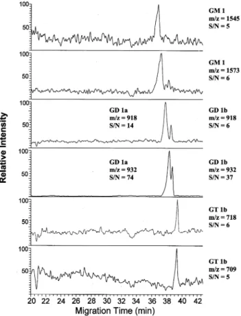
Using the same ganglioside mixture, the makeup liquid composition was studied to optimize sensitivity. A solution of 2-propanol/water (80:20) containing 1% ammonia provided the best results. The signal intensity at different makeup flow rates was also studied. The results showed that the optimum flow rate was 400 nL/min. Mass electropherograms of gangliosides analyzed under these optimized conditions appear in Figure 5. As can be seen, the two disialoganglioside isomers (GD 1a, GD 1b) were resolved and peaks with different chain lengths were also detected for GM1, GD1a, and GD1b.
CONCLUSIONS
A CE/ESI-MS interface suitable for MEKC and nonvolatile CZE analysis was developed. The interface described herein represents an extension of our previous work, which demonstrated the ability to incorporate a sheath liquid without undergoing an excessive
dilution of the CE effluent.17In contrast to the previous low-flow
design, which utilized a flat tip, the present interface incorporates a beveled edge emitter. Because the present design has the same optimum flow rate, but uses a larger orifice diameter (75 vs 25 µm), it provides similar ESI-MS sensitivity with fewer issues Figure 4. Electropherogram of type III gnagliosides. The separation
potential was+20 kV, and the UV wavelength was set at 200 nm. Running buffer was 40 mM borate and 20 mMR-CD at pH 10.6. Peaks: 1, 1′, GM1; 2, 2′, GD1a; 3, 3′, GD1b; 4)GT1b.
Chart 1. Structures of the Gangliosides
Figure 5. Mass electropherograms of 4 mg/mL ganglioside mixture using the low-makeup beveled tip interface in negative ion mode. The makeup liquid (80% 2-propanol with 1% ammonium hydroxide) was delivered at a flow rate of 400 nL/min. The potential applied to the buffer reservoir was+20 kV, and the ESI voltage was set at-2 kV.
Downloaded by NATIONAL TAIWAN UNIV on July 31, 2009
related to column plugging. Another important modification of this design is the use of a makeup column, which allows the control of the final spray solution. The analysis of triazine and phenolic mixtures demonstrates the potential of this interface for MEKC/ ESI-MS applications in both positive and negative ion modes, respectively. Even more significant was the demonstration of CE/ ESI-MS operation using nonvolatile buffers. Considering the fact that nonvolatile buffers are used in many CE applications, this
interface provides a welcomed alternative to existing CE/ESI-MS interfaces.
ACKNOWLEDGMENT
This work was supported by the National Research Council of the Republic of China.
Received for review May 7, 2004. Accepted August 20, 2004.
AC049330I
Downloaded by NATIONAL TAIWAN UNIV on July 31, 2009