Research Article
The Photocatalytic Activity and Compact Layer
Characteristics of TiO
2
Films Prepared Using Radio
Frequency Magnetron Sputtering
H. C. Chang,
1H. H. Huang,
2C. Y. Wu,
2R. Q. Hsu,
1and C. Y. Hsu
21Department of Mechanical Engineering, National Chiao Tung University, 1001 University Road, Hsinchu 30010, Taiwan
2Department of Mechanical Engineering, Lunghwa University of Science and Technology, No. 300, Sec. 1, Wanshou Road, Guishan,
Taoyuan 33306, Taiwan
Correspondence should be addressed to C. Y. Hsu; [email protected]
Received 7 March 2014; Revised 18 April 2014; Accepted 18 April 2014; Published 22 May 2014 Academic Editor: Ho Chang
Copyright © 2014 H. C. Chang et al. This is an open access article distributed under the Creative Commons Attribution License, which permits unrestricted use, distribution, and reproduction in any medium, provided the original work is properly cited.
TiO2compact layers are used in dye-sensitized solar cells (DSSCs) to prevent charge recombination between the electrolyte and
the transparent conductive substrate (indium tin oxide, ITO; fluorine-doped tin oxide, FTO). Thin TiO2 compact layers are
deposited onto ITO/glass by means of radio frequency (rf) magnetron sputtering, using deposition parameters that ensure greater photocatalytic activity and increased DSSC conversion efficiency. The photoinduced decomposition of methylene blue (MB) and
the photoinduced hydrophilicity of the TiO2thin films are also investigated. The photocatalytic performance characteristics for the
deposition of TiO2films are improved by using the Grey-Taguchi method. The average transmittance in the visible region exceeds
85% for all samples. The XRD patterns of the TiO2films, for sol-gel with spin coating of porous TiO2/TiO2compact/ITO/glass,
show a good crystalline structure. In contrast, without the TiO2compact layer (only porous TiO2), the peak intensity of the anatase
(101) plane in the XRD patterns for the TiO2film has a lower value, which demonstrates inferior crystalline quality. With a TiO2
compact layer to prevent charge recombination, a higher short-circuit current density is obtained. The DSSC with the FTO/glass and Pt counter electrode demonstrates the energy conversion efficiency increased.
1. Introduction
Dye-sensitized solar cells (DSSCs) have been extensively studied as a promising alternative to conventional solar cells that use a p-n junction because of their reasonable conversion efficiency, low cost, environmentally friendly components, use of a flexible cell design, and simple fabrication process, when compared to silicon solar cells [1]. DSSCs are the next-generation solar cells [2]. If low cost and highly efficient DSSCs can be developed, it will be an important new direc-tion for the development of solar cells. A typical DSSC consists of dye molecules that act as sensitizers, a nanoporous metal oxide film (TiO2semiconductor material), a transpar-ent conducting oxide (indium tin oxide, ITO), an electrolyte charge carrier, and a counter electrode (Pt or carbon) [3]. The dye and metal oxide, which are used for the sensitizer and
the electrode, respectively, are important to the photoelectric conversion efficiency of DSSCs [4].
TiO2is one of the most popular photocatalytic materials, so it has many commercial applications, such as antibacterial applications, waste purification, self-cleaning, and sensors [5]. It is also used for photoelectrodes and in high perfor-mance DSSC applications because it has an adequate photore-sponse and effective electron transport [6]. A high incident photon to current conversion efficiency is expected for TiO2 films that have a better phase structure and crystallinity and a higher specific surface area [7]. The control of the TiO2 nanostructures is very important for the photovoltaic performance of a DSSC [8]. In order to improve the con-version efficiency of DSSCs, several studies have focused on the structural design, material development, photovoltaic characterization, and analysis of the mechanism of TiO2
Volume 2014, Article ID 786165, 8 pages http://dx.doi.org/10.1155/2014/786165
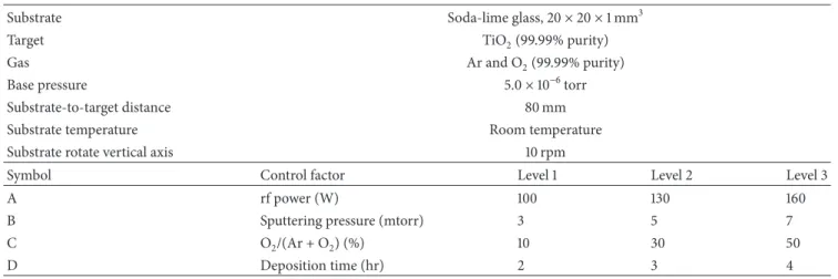
Table 1: The factor and level settings for sputter deposition of TiO2compact layers.
Substrate Soda-lime glass, 20× 20 × 1 mm3
Target TiO2(99.99% purity)
Gas Ar and O2(99.99% purity)
Base pressure 5.0× 10⁻⁶torr
Substrate-to-target distance 80 mm
Substrate temperature Room temperature
Substrate rotate vertical axis 10 rpm
Symbol Control factor Level 1 Level 2 Level 3
A rf power (W) 100 130 160
B Sputtering pressure (mtorr) 3 5 7
C O2/(Ar + O2) (%) 10 30 50
D Deposition time (hr) 2 3 4
nanoparticles [9]. Mesoporous TiO2 is widely used as an electrode in DSSCs to produce a high surface area for the adsorption of a greater density of dye molecules, which produces a significant increase in the photocurrent [10]. However, the highly porous structure of the TiO2 layer can cause an electrical shortage and recombination of the charge/electrons, which interferes with the unidirectional electron transport that takes place at the TiO2 layer/dye molecule and ITO/TiO2layer interfaces [11]. This leakage by electronic back transfer leads to a decrease in cell efficiency. To avoid this problem, the primary method used to prevent recombination is the use of a TiO2compact layer (blocking layer) between the ITO and the porous TiO2 layer [11]. This compact layer can be prepared using many growth techniques, such as sputter deposition, dip-coating, chemical vapor deposition, and spray pyrolysis.
This study determines the optical, structural, and surface properties of a TiO2 compact layer that is grown by radio frequency (rf) magnetron sputtering on the ITO electrodes, as a function of the deposition parameters that ensure higher photocatalytic activity and greater DSSC conversion efficiency. The nanoporous TiO2upper layer is coated using the sol-gel process and calcination at 450∘C. Moreover, the working electrode which is made of a dye-sensitized TiO2 film that is immobilized onto a fluorine-doped tin oxide (FTO) substrate is also investigated.
The Taguchi method is a powerful tool for the design of high quality systems, which can be used to design low cost products, with improved quality [12]. To optimize the deposition process for TiO2photocatalytic films, a statistical analysis of the signal-to-noise ratio (𝑆/𝑁) is performed, using an analysis of variance (ANOVA). The optimal deposition parameters are obtained by analyzing the results for various experimental permutations [13,14].Table 1shows the effect on the quality of the TiO2photocatalytic films of four depo-sition parameters at three levels: the rf power, the sputtering pressure, the Ar-O2ratio, and the deposition time. An L9(34, with four columns and nine rows) orthogonal array is used.
2. Experimental
The TiO2 photocatalytic thin films (compact layer) were coated onto ITO/glass substrates (and FTO/glass), using rf magnetron sputtering. The reactive and sputtering gases were O2 (purity: 99.99%) and Ar (purity: 99.99%), respectively. The commercially available, hot pressed, and sintered ceramic target TiO2 had a diameter of 50.8 mm and 99.99% purity (Elecmat, USA).
Prior to coating, the target was presputtered for 15 min, in order to remove any contamination, and the substrates were ultrasonically cleaned and degreased in acetone, rinsed in deionised water, and subsequently dried with nitrogen gas. A vacuum, of base pressure 5.0× 10⁻⁶Torr, was applied before deposition. The distance between the substrate and the target (80 mm) and the rotational speed of the substrate (10 rpm) were constant. By adjusting the experimental permutations, this study determined the effect of each deposition parameter on the deposition rate for TiO2/ITO/glass, the methylene blue (MB) absorbance, the contact angle to a pure water droplet, the surface morphology, and the crystal structure.
The porous TiO2 film (p-TiO2) was coated onto the TiO2 compact/ITO/glass (and TiO2 compact/FTO/glass) using a mixture of TiO2 powders (P-25, particle size: <25 nm, 99.7%) with the TiO2 sol-gel component studied
in [15]. The TiO2 sol-gel was mixed with 0.3 g of com-mercially available Degussa P-25, to avoid any cracking of the film. The TiO2sol-gel was produced using spin coating and blade coating. The gels were predried for 15 min at 50∘C and then sintered in a box furnace at 450∘C (heat-ing rate 10∘C/min) for 30 min in air ambient, to produce the bare TiO2 electrode used in this work to fabricate the DSSC. The porous TiO2 films were immersed into the dye solution (0.4 mM N719 dye solution, Solaronix, Switzer-land, Di-tetrabutylammonium cis-bis(isothiocyanato)bis(2, 2-bipyridyl-4,4-dicarboxylato)-ruthenium(II); chemical formula C58H86N8O8RuS2; Mol Wt: 1188.55) complex for 24 h at room temperature.
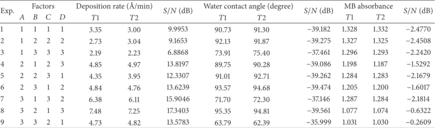
Table 2: The experimental results and the𝑆/𝑁 ratios for the deposition rate, the contact angle, and the MB absorbance for the TiO2compact layer coatings (the experiments were repeated twice).
Exp. Factors Deposition rate ( ˚A/min) 𝑆/𝑁 (dB) Water contact angle (degree) 𝑆/𝑁 (dB) MB absorbance 𝑆/𝑁 (dB)
𝐴 𝐵 𝐶 𝐷 𝑇1 𝑇2 𝑇1 𝑇2 𝑇1 𝑇2 1 1 1 1 1 3.35 3.00 9.9953 90.73 91.30 −39.182 1.328 1.332 −2.4770 2 1 2 2 2 2.73 3.04 9.1653 92.13 91.87 −39.275 1.327 1.325 −2.4508 3 1 3 3 3 2.19 2.23 6.8868 73.91 75.40 −37.461 1.296 1.293 −2.2420 4 2 1 2 3 4.85 4.97 13.8197 89.75 90.28 −39.086 1.198 1.187 −1.5292 5 2 2 3 1 4.35 3.95 12.3307 91.01 92.71 −39.262 1.284 1.283 −2.1679 6 2 3 1 2 4.84 4.76 13.6239 93.57 94.68 −39.474 1.205 1.200 −1.6017 7 3 1 3 2 6.38 6.11 15.9046 71.70 72.30 −37.146 1.287 1.284 −2.1814 8 3 2 1 3 7.48 7.25 17.3403 95.35 94.81 −39.561 1.077 1.074 −0.6322 9 3 3 2 1 4.73 4.82 13.5783 63.79 62.39 −35.999 1.031 1.030 −0.2609
Note:𝐴 = rf power (W), 𝐵 = process pressure (Pa), 𝐶 = O2/(Ar + O2) flow rate ratio (%), and𝐷 = deposition time (hr).
Glass ITO Pt/carbon Blade/spin coating Sputter coating ITO Glass
Figure 1: A schematic diagram of a DSSC with an rf-sputtered TiO2
compact layer/ITO/glass on the ITO electrode.
The Pt counter electrode was coated onto ITO/glass (and FTO/glass) substrates using DC sputtering with pure Ar gas and a DC power of 30 W. The dye-adsorbed TiO2working electrode and the counter electrode were assembled into a sandwich-type cell and sealed with a hot-melt sealant.
Figure 1shows a schematic diagram of a DSSC with an
rf-sputtered TiO2 compact layer/ITO/glass on the ITO elec-trode. In order to prevent the leakage by electron transfer to the liquid electrolyte, dense TiO2 passivating layers were used.
The phase identification of the particles produced using various deposition parameters was performed by X-ray diffraction (Rigaku-2000 spectrometer), using Cu-K𝛼 radi-ation (40 kV, 30 mA, and𝜆 = 0.1541 nm). The photoinduced hydrophilicity of the TiO2 thin films was evaluated by measurement of the contact angle to pure water, using a contact angle meter (FACE CAVP150) that is accurate to less than 1∘. A black light (UVP UVL-225D) lamp with a principal wavelength of 365 nm (1.5 mW/cm2 at the film surface) was the UV light source. The decomposition of MB aqueous solution (10𝜇M) was photocatalyzed. An UV-Vis-NIR spectrometer (Jasco V-670) was used to measure the absorption spectra of the MB solution as a function of the UV irradiation time. The film thickness was measured, using
a surface profilometer (𝛼-step, AMBIOS XP-1). The surface morphology was analyzed using a field emission scanning electron microscope (FESEM, JEOL JSM-6500F). The crystal structure of the films was characterized by X-ray diffraction (Rigaku-2000 spectrometer), using Cu-K𝛼 radiation (40 kV, 30 mA, and𝜆 = 0.1541 nm), with a grazing incidence angle of 1∘. The scanning rate was 5∘/min.
The power used to test the prepared DSSC was a 150 W Xe lamp, which simulates sunlight (AM 1.5). Before the test, the distance between the light source and the sample was adjusted to allow a light source density of 100 mW/cm2. The cell performance parameters, including the short-circuit current density (𝐽sc), the open-circuit voltage (𝑉oc), the fill factor (FF),
and the photoelectronic conversion efficiency(𝜂(%) = 𝐽sc×
𝑉oc × FF/total incident energy × 100), were measured and
calculated using the𝐽-𝑉 characteristics of DSSC.
3. Results and Discussion
3.1. The Photocatalytic Activity of the TiO2 Compact Films.
The TiO2compact films were deposited onto ITO soda-lime glass substrates. The optimization of the parameter settings involved comparing the signal-noise (𝑆/𝑁) ratios, using the Taguchi method. In order to optimize the TiO2compact films deposition parameters, the water contact angle and the MB absorbance had the smaller the better characteristics and the deposition rate had the larger the better characteristics. The respective𝑆/𝑁 ratios for the smaller the better characteristic and the larger the better characteristic are expressed as follows (Taguchi et al. [13]):
(𝑆 𝑁)𝑆= −10 log 1 𝑛 𝑛 ∑ 𝑖=1 𝑦2𝑖 (𝑆 𝑁)𝐿= −10 log 1 𝑛 𝑛 ∑ 𝑖=1 1 𝑦2 𝑖 , (1)
where𝑛 is the number of iterations for the experiment and 𝑦𝑖 is the𝑖th average value of the characteristic measured.
Table 3: The ANOVA results for the deposition rate, the water contact angle, and the MB absorbance.
Factor Degree of freedom Sum of square Variance Contribution (P %)
Deposition rate ( ˚A/min)
𝐴 2 74.4166 37.2083 84.45
𝐵 2 6.1132 3.0566 6.93
𝐶 2 6.1644 3.0822 7.00
𝐷 2 1.4211 0.7106 1.62
Total 8 88.1153 100
Water contact angle (degree)
𝐴 2 4.4559 2.22793 33.68 𝐵 2 4.4483 2.22417 33.62 𝐶 2 3.7790 1.88950 28.56 𝐷 2 0.5472 0.27359 4.14 Total 8 13.2304 100 MB absorbance 𝐴 2 2.80223 1.40111 54.36 𝐵 2 0.72560 0.36280 14.07 𝐶 2 1.03120 0.51560 20.00 𝐷 2 0.59634 0.29817 11.57 Total 8 5.15538 100
Using (1), the 𝑆/𝑁 ratio values were computed for depo-sition rate, water contact angle, and MB absorbance in the TiO2 compact layers coatings, as shown in Table 2. The hydrophilicity of the TiO2 films was determined by measuring the water contact angle. The change in the water contact angle is shown as a function of UV irradiation time for the TiO2 films deposited with parameter sets in the orthogonal arrays (Table 2). When the TiO2 film surface is irradiated by UV light for 12 min, the water contact angles of all of the films begin to decrease (less than 63∘, sample number 9), which indicates that the film surface becomes more hydrophilic. The absorption spectra for the MB aqueous solution degraded by TiO2photocatalytic film after 240 min UV irradiation are shown for the orthogonal array settings
(Table 2). The TiO2films deposited using the parameter sets
in the orthogonal arrays from number 1 to number 9 show MB absorbance between 1.33 and 1.03.
An analysis of variance (ANOVA) was used to determine the effect of a change in the process parameters on the process response.Table 3shows the ANOVA results for the deposi-tion rate, the water contact angle, and the MB absorbance.
Table 3shows that the variables that most significantly affect
the deposition rate, the water contact angle, and the MB absorbance are the rf power (𝑃 = 84.45%, 33.68%, and 54.36%), the sputtering pressure (𝑃 = 6.93%, 33.62%, and 14.07%), and the argon-oxygen ratio (𝑃 = 7.00%, 28.56%, and 20.00%).
Grey relational analysis (GRA) provides an efficient solu-tion to difficult problems that involve multiple performance characteristics that are uncertain, have multiple inputs, and
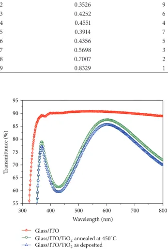
Table 4: The Grey relational grade and its ranking for the TiO2
compact layer coatings.
Exp. Grey relational grade Rank
1 0.3595 8 2 0.3526 9 3 0.4252 6 4 0.4551 4 5 0.3914 7 6 0.4356 5 7 0.5698 3 8 0.7007 2 9 0.8329 1 300 400 500 600 700 800 55 60 65 70 75 80 85 90 95 T ra n smi tt ance (%) Wavelength (nm) Glass/ITO Glass/ITO/TiO2annealed at450∘C Glass/ITO/TiO2as deposited
Figure 2: The optical transmittance spectra for TiO2 compact
layer/ITO/glass.
generate discrete data. The objective of this study is to opti-mize the deposition parameters for the TiO2compact films using GRA, which is used extensively in various industries [16].
The optimum combination does not yield suitable process parameters with a single performance characteristic (Taguchi method) for the TiO2 compact films coated. In order to optimize the deposition parameters, the deposition rate, the contact angle, and the MB absorbance, multiple performance characteristics (grey relational analysis) must be analyzed. The calculated grey relational grade is taken as the inspected value in the Taguchi method.Table 4shows the grey rela-tional grade and its ranking for the TiO2 compact layer coatings. A comparison of the experimental results for the orthogonal array (𝐴3𝐵3𝐶2𝐷1) and the photocatalytic activity optimal parameter set (𝐴3𝐵3𝐶2𝐷3) for TiO2film deposition is shown inTable 5. The multiple performance characteristics for the deposition of TiO2 thin films are greatly improved
Table 5: The confirmation test results for the multiple performance characteristics, using the initial and the optimal process parameters.
Level Initial process parameters Optimal process parameters Improvement rate (%)
𝐴3𝐵3𝐶2𝐷1 𝐴3𝐵3𝐶2𝐷3
Deposition rate ( ˚A/min) 4.775 5.48 12.87
Contact angle (degree) 63.09 53.47 15.25
MB absorbance 1.0305 0.865 16.06
(a) (b) (c)
Figure 3: (a) The SEM images for sputtered TiO2 compact layer on ITO/glass, (b) the SEM images for porous TiO2 onto TiO2
compact/ITO/glass, produced using the sol-gel with spin coating method, and (c) the SEM images for porous TiO2 onto TiO2
compact/ITO/glass, produced using the sol-gel with blade coating method.
Sputter coating ITO Glass 1 𝜇m Spin coating (a) Sputter coating ITO 1 𝜇mGlass Blade coating (b)
Figure 4: The SEM cross-sectional image of TiO2(a) corresponding toFigure 3(b)and (b) corresponding toFigure 3(c).
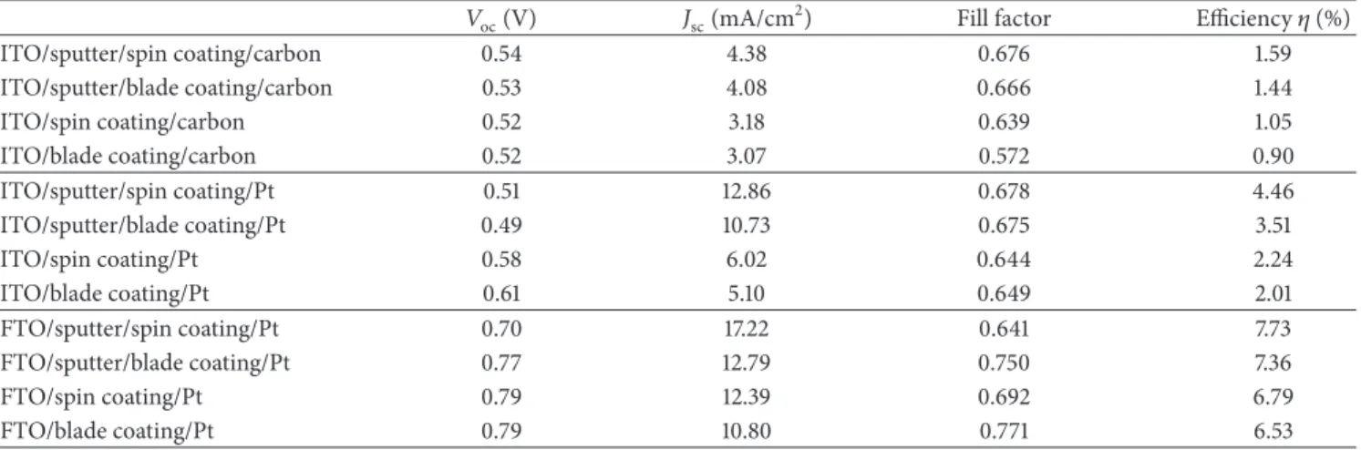
Table 6: The performance of a DSSC prepared using a photoelectrode with and without a TiO2compact layer, using carbon and Pt counter
electrodes, and using ITO/glass and FTO/glass.
𝑉oc(V) 𝐽sc(mA/cm2) Fill factor Efficiency𝜂 (%)
ITO/sputter/spin coating/carbon 0.54 4.38 0.676 1.59 ITO/sputter/blade coating/carbon 0.53 4.08 0.666 1.44 ITO/spin coating/carbon 0.52 3.18 0.639 1.05 ITO/blade coating/carbon 0.52 3.07 0.572 0.90 ITO/sputter/spin coating/Pt 0.51 12.86 0.678 4.46 ITO/sputter/blade coating/Pt 0.49 10.73 0.675 3.51 ITO/spin coating/Pt 0.58 6.02 0.644 2.24 ITO/blade coating/Pt 0.61 5.10 0.649 2.01 FTO/sputter/spin coating/Pt 0.70 17.22 0.641 7.73 FTO/sputter/blade coating/Pt 0.77 12.79 0.750 7.36 FTO/spin coating/Pt 0.79 12.39 0.692 6.79 FTO/blade coating/Pt 0.79 10.80 0.771 6.53
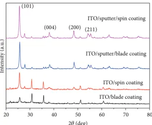
20 30 40 50 60 70 80 (211) (200) In te n si ty (a.u .) ITO/sputter/spin coating ITO/blade coating ITO/spin coating ITO/sputter/blade coating (101) (004) 2𝜃 (deg)
Figure 5: The XRD patterns for the TiO2films after being annealed at 450∘C.
by using the Grey-Taguchi method. The improvement in the deposition rate is 12.87%, that in the water contact angle is 15.25%, and that in the MB absorbance is 16.06%.
The transmittance spectra are shown as a function of wavelengths in the range between 300 and 800 nm for TiO2 compact layers inFigure 2. The average transmittance in the visible region exceeds 85% for all samples, but transmission in the UV-near visible region decreases abruptly. After annealing treatment, the optical transmittance of the film is increased.
3.2. DSSC Conversion Efficiency. SEM analysis was used
to determine the morphology of the sputtered TiO2 com-pact layers (with photocatalytic activity optimal parame-ters, 𝐴3𝐵3𝐶2𝐷3) on the ITO substrate and the thick TiO2 porous layer produced using the sol-gel method, as shown in
Figure 3. The uniform and smooth surfaces of the sputtered
compact accumulation film are well covered by spherical particles, which are densely coated with a small grain size
(Figure 3(a), TiO2compact/ITO/glass). This is necessary to
prevent charge recombination between the ITO and the porous TiO2 layer [17, 18]. The SEM images show the porous TiO2film over the sputtered compact layer, produced using the sol-gel with spin coating method (Figure 3(b), porous TiO2/TiO2compact/ITO/glass) and the sol-gel with blade coating method (Figure 3(c), porous TiO2/TiO2 com-pact/ITO/glass). The porous TiO2film structure is not dense and the crystallite size of the TiO2 is increased. DSSC efficiency is improved by producing a TiO2electrode with a large surface area and optimum pore structure [19,20].
The cross-section of the TiO2films was observed by SEM.
Figure 4(a)corresponds toFigure 3(b)andFigure 4(b)
corre-sponds toFigure 3(c). The TiO2compact/ITO films produced using the photocatalytic activity optimal deposition condi-tions (𝐴3𝐵3𝐶2𝐷3) are highly compacted and homogeneous and adhere perfectly to the glass substrate. These results
confirm a spongelike structure for the TiO2layer (Figure 4), which is a prerequisite for a highly efficient DSSC [21]. The characteristics of the TiO2 materials depend significantly upon the surface morphology, the crystal structure, and the crystallization.
Figure 5shows that the XRD patterns of the TiO2films,
produced using the sol-gel with spin coating of porous TiO2/TiO2 compact/ITO/glass, show a good crystalline structure and anatase (101) diffraction peaks that demonstrate a higher crystallinity than the other films. In contrast, without the TiO2compact layer (only porous TiO2), the peak intensity of the anatase (101) plane in the XRD patterns for the TiO2 film has a lower value, which demonstrates inferior crystalline quality.
Good performance for the counter electrode requires a low internal resistance and raw material cost. The best material for the counter electrode is Pt, which shows excellent electrochemical activity for I3−reduction at film thicknesses of 2∼10 nm [22, 23]. Figure 6 shows the photo current-voltage (𝐼-𝑉) characteristics for the DSSC under AM1.5 solar irradiation with 100 mW/cm2 illumination, with and without the TiO2compact layer.Figure 6(a)shows a carbon counter electrode and ITO/glass, Figure 6(b) shows a Pt counter electrode and ITO/glass, and Figure 6(c) shows a Pt counter electrode and FTO/glass [24]. The corresponding cell parameters are summarized inTable 6, which shows the performance of the DSSC. With a TiO2 compact layer to prevent charge recombination, a higher𝐽scis obtained. The
energy conversion efficiency (𝜂) increases if a Pt counter electrode is used instead of a carbon counter electrode.
For the purposes of comparison, the energy conversion efficiency for the DSSC film deposited on FTO glass is also given. FTO substrates have good optoelectronic performance and higher energy conversion efficiency than ITO substrates.
Table 6 shows that a FTO/sputter/spin coating/PT setup
increases the conversion efficiency of the DSSC, with𝑉oc =
0.70 V, 𝐽sc = 17.22 mA/cm2, a fill factor = 0.641, and an energy
0.0 0.1 0.2 0.3 0.4 0.5 0 1 2 3 4 Voltage (V) ITO/sputter/spin coating/carbon ITO/sputter/blade coating/carbon ITO/spin coating/carbon ITO/blade coating/carbon C u rr en t den si ty (mA/cm 2) (a) 0.0 0.1 0.2 0.3 0.4 0.5 0.6 0 2 4 6 8 10 12 14 ITO/sputter/spin coating/Pt ITO/sputter/blade coating/Pt ITO/spin coating/Pt ITO/blade coating/Pt Voltage (V) C u rr en t den si ty (mA/cm 2) (b) 0.0 0.1 0.2 0.3 0.4 0.5 0.6 0.7 0.8 0 3 6 9 12 15 Voltage (V) FTO/sputter/spin coating/Pt FTO/sputter/blade coating/Pt FTO/spin coating/Pt FTO/blade coating/Pt 18 C u rr en t den si ty (mA/cm 2 ) (c)
Figure 6: The𝐼-𝑉 characteristics for DSSCs fabricated with and without a TiO2compact layer, (a) using a carbon counter electrode and
ITO/glass, (b) using a Pt counter electrode and ITO/glass, and (c) using a Pt counter electrode and FTO/glass, under AM 1.5 solar irradiation
with a density of 100 mW/cm2.
4. Conclusion
TiO2 films (compact layer) are coated onto ITO/glass sub-strates (and FTO/glass), using rf magnetron sputtering. The reactive and sputtering gases are O2and Ar, respectively. The multiple performance characteristics for the deposited TiO2 compact films’ photocatalytic activity are greatly improved by using the Grey-Taguchi method. The improvement in the deposition rate is 12.87%, that in the water contact angle is 15.25%, and that in the MB absorbance is 16.06%. The porous
TiO2film that covers the sputtered compact layer produced by the sol-gel method has a structure which is not dense and a crystallite size that is increased. The XRD patterns for TiO2films produced using sol-gel with spin coating of porous TiO2/TiO2 compact/ITO/glass result in a good crystalline structure and the anatase (101) diffraction peaks demonstrate a higher degree of crystallinity. The energy conversion effi-ciency (𝜂) for a Pt counter electrode is greater than that for a carbon counter electrode. The experimental results show that FTO/sputter/spin coating/PT setup increases
the conversion efficiency of the DSSC, with 𝑉oc = 0.70 V,
𝐽sc = 17.22 mA/cm2, the fill factor = 0.641, and an energy
conversion efficiency as high as 7.73%.
Conflict of Interests
The authors declare that there is no conflict of interests regarding the publication of this paper.
Acknowledgments
The authors gratefully acknowledge the support of the Kung Chi Technology Co., Ltd., the Ministry of Education of Taiwan, through Grant nos. 102G-88-022 and 102 M-88-021, and the Chung-Shan Institute of Science & Technology (Armaments Bureau).
References
[1] Y.-S. Jin, K.-H. Kim, W.-J. Kim, K.-U. Jang, and H.-W. Choi,
“The effect of RF-sputtered TiO2passivating layer on the
per-formance of dye sensitized solar cells,” Ceramics International, vol. 38, no. 1, pp. S505–S509, 2012.
[2] K. Nithyanandam and R. Pitchumani, “Analysis and design of dye-sensitized solar cell,” Solar Energy, vol. 86, no. 1, pp. 351– 368, 2012.
[3] H. Chang, T. L. Chen, K. D. Huang, S. H. Chien, and K. C. Hung, “Fabrication of highly efficient flexible dye-sensitized solar cells,” Journal of Alloys and Compounds, vol. 504, no. 1, pp. S435–S438, 2010.
[4] K. R. Bae, C. H. Ko, Y. Park et al., “Structure control of
nanocrys-talline TiO2for the dye-sensitized solar cell application,”
Cur-rent Applied Physics, vol. 10, no. 3, pp. S406–S409, 2010. [5] C. G. Kuo, C. Y. Hsu, S. S. Wang, and D. C. Wen, “Photocatalytic
characteristics of TiO2films deposited by magnetron sputtering
on polycarbonate at room temperature,” Applied Surface Science, vol. 258, pp. 6952–6957, 2012.
[6] C.-T. Wang and C.-F. Yen, “Titania nanocomposite thin films with enhanced photovoltaic efficiency: effects of Ti-alkoxide sol and compact layer,” Surface and Coatings Technology, vol. 206, no. 8-9, pp. 2622–2627, 2012.
[7] M. C. Kao, H. Z. Chen, and S. L. Young, “Dye-sensitized solar
cells with TiO2nanocrystalline films prepared by conventional
and rapid thermal annealing processes,” Thin Solid Films, vol. 519, no. 10, pp. 3268–3271, 2011.
[8] S. Yuan, Y. Li, Q. Zhang, and H. Wang, “Anatase TiO2sol as a
low reactive precursor to form the photoanodes with compact films of dye-sensitized solar cells,” Electrochimica Acta, vol. 79, pp. 182–188, 2012.
[9] J. Yu, Q. Li, and Z. Shu, “Dye-sensitized solar cells based on
double-layered TiO2 composite films and enhanced
photo-voltaic performance,” Electrochimica Acta, vol. 56, no. 18, pp. 6293–6298, 2011.
[10] L. Meng, T. Ren, and C. Li, “The control of the diameter of the nanorods prepared by dc reactive magnetron sputtering and the applications for DSSC,” Applied Surface Science, vol. 256, no. 11, pp. 3676–3682, 2010.
[11] H. J. Kim, J. D. Jeon, D. Y. Kim, J. J. Lee, and S. Y. Kwak, “Im-proved performance of dye-sensitized solar cells with compact
TiO2blocking layer prepared using low-temperature reactive
ICP-assisted DC magnetron sputtering,” Journal of Industrial and Engineering Chemistry, vol. 18, pp. 1807–1812, 2012. [12] C.-C. Chen, C.-C. Tsao, Y.-C. Lin, and C.-Y. Hsu, “Optimization
of the sputtering process parameters of GZO films using the Grey-Taguchi method,” Ceramics International, vol. 36, no. 3, pp. 979–988, 2010.
[13] G. Taguchi, E. A. Elsayed, and T. Hsaing, Quality Engineering in Production Systems, McGraw-Hill, New York, NY, USA, 1989. [14] P. C. Huang, C. H. Huang, M. Y. Lin, C. Y. Chou, C. Y. Hsu,
and C. G. Kuo, “The effect of sputtering parameters on the film properties of molybdenum back contact for CIGS solar cells,” International Journal of Photoenergy, vol. 2013, Article ID 390824, 8 pages, 2013.
[15] L. Zhang, Y. Zhu, Y. He, W. Li, and H. Sun, “Preparation and
per-formances of mesoporous TiO2film photocatalyst supported on
stainless steel,” Applied Catalysis B: Environmental, vol. 40, no. 4, pp. 287–292, 2003.
[16] J. L. Deng, The Essential Method of Grey Systems, HUST Press, Wuhan, China, 1992.
[17] S. Vijayalakshmy and B. Subramanian, “Enhanced performance
of dye-sensitized solar cells with TiO2 blocking layers and
Pt counter electrodes prepared by physical vapor deposition (PVD),” Electrochimica Acta, vol. 116, pp. 334–342, 2014. [18] C. G. Kuo, C. F. Yang, L. R. Hwang, and J. S. Huang, “Effects
of titanium oxide nanotube arrays with different lengths on the characteristics of dye-sensitized solar cells,” International Journal of Photoenergy, vol. 2013, Article ID 650973, 6 pages, 2013.
[19] K. H. Ko, Y. C. Lee, and Y. J. Jung, “Enhanced efficiency of
dye-sensitized TiO2 solar cells (DSSC) by doping of metal ions,”
Journal of Colloid and Interface Science, vol. 283, no. 2, pp. 482– 487, 2005.
[20] C. G. Kuo, C. F. Yang, M. J. Kao et al., “An analysis and research on the transmission ratio of dye sensitized solar cell photoelec-trodes by using different etching process,” International Journal of Photoenergy, vol. 2013, Article ID 151973, 8 pages, 2013. [21] M. Hocevar, U. O. Krasovec, M. Bokalic et al., “Sol-gel based
TiO2paste applied in screen-printed dye-sensitized solar cells
and modules,” Journal of Industrial and Engineering Chemistry, vol. 19, pp. 1464–1469, 2013.
[22] C. H. Yoon, R. V. R. Vittal, J. Lee, W.-S. Chae, and K.-J. Kim, “Enhanced performance of a dye-sensitized solar cell with an electrodeposited-platinum counter electrode,” Electrochimica Acta, vol. 53, no. 6, pp. 2890–2896, 2008.
[23] H. Chang, C. H. Chen, M. J. Kao, S. H. Chien, and C. Y. Chou, “Photoelectrode thin film of dye-sensitized solar cell fabricated by anodizing method and spin coating and electrochemical impedance properties of DSSC,” Applied Surface Science, vol. 275, pp. 252–257, 2013.
[24] M. H. Abdullah and M. Rusop, “Multifunctional graded index
TiO2 compact layer for performance enhancement in dye
sensitized solar cell,” Applied Surface Science, vol. 284, pp. 278– 284, 2013.
Submit your manuscripts at
http://www.hindawi.com
Hindawi Publishing Corporation
http://www.hindawi.com Volume 2014
Inorganic Chemistry
International Journal of
Hindawi Publishing Corporation
http://www.hindawi.com Volume 2014
Photoenergy
Hindawi Publishing Corporation
http://www.hindawi.com Volume 2014
Carbohydrate
Chemistry
International Journal ofHindawi Publishing Corporation
http://www.hindawi.com Volume 2014
Journal of
Chemistry
Hindawi Publishing Corporation
http://www.hindawi.com Volume 2014
Physical Chemistry
Hindawi Publishing Corporation http://www.hindawi.com Analytical Methods in Chemistry Journal of Volume 2014 Bioinorganic Chemistry and Applications Hindawi Publishing Corporation
http://www.hindawi.com Volume 2014
Spectroscopy
International Journal ofHindawi Publishing Corporation
http://www.hindawi.com Volume 2014
The Scientific
World Journal
Hindawi Publishing Corporation
http://www.hindawi.com Volume 2014
Medicinal Chemistry Hindawi Publishing Corporation
http://www.hindawi.com Volume 2014
Chromatography Research International
Hindawi Publishing Corporation
http://www.hindawi.com Volume 2014
Applied ChemistryJournal of
Hindawi Publishing Corporation
http://www.hindawi.com Volume 2014
Hindawi Publishing Corporation
http://www.hindawi.com Volume 2014
Theoretical Chemistry
Journal of
Hindawi Publishing Corporation
http://www.hindawi.com Volume 2014
Journal of
Spectroscopy
Analytical Chemistry
Hindawi Publishing Corporation
http://www.hindawi.com Volume 2014
Journal of Hindawi Publishing Corporation
http://www.hindawi.com Volume 2014 Quantum Chemistry
Hindawi Publishing Corporation
http://www.hindawi.com Volume 2014 International
Electrochemistry
International Journal ofHindawi Publishing Corporation
http://www.hindawi.com Volume 2014
Hindawi Publishing Corporation
http://www.hindawi.com Volume 2014