A Multisymbol Context-Based Arithmetic Coding
Architecture for MPEG-4 Shape Coding
Kun-Bin Lee, Member, IEEE, Jih-Yiing Lin, and Chein-Wei Jen, Member, IEEE
Abstract—MPEG-4 shape coding comprises context-based
arithmetic encoding (CAE) as its centerpiece. Since the CAE algorithm has a complicated coding procedure and strong data dependency, it is hard to exploit its pipeline and parallel facilities. Furthermore, to encode multiple symbols within one clock cycle, it needs to overcome the issues of extracting multiple contexts of these symbols, deriving multiple probabilities from these contexts, and performing multiple multiplicative range update operations. This paper presents an efficient pipelined multisymbol CAE architecture for real-time MPEG-4 shape encoding. The proposed design is based on the inherent characteristics of binary alpha blocks as well as the numerical properties of the probabilities indexed by the contexts, and it is capable of encoding either a singe symbol or multiple symbols within each clock cycle. To overcome the aforementioned issues under the consideration of the hardware cost and the critical path delay, only symbols with a particular set of contexts are chosen to be processed simultaneously within the same clock cycle. Theoretical analysis shows that the majority of symbols have contexts belonging to this particular set, and there-fore CAE processing can be significantly accelerated. An example VLSI implementation of proposed architecture that encodes two symbols within each clock cycle without sacrificing the clock rate can achieve a speedup of 1.47 in comparison with traditional CAE architectures. This particular two-symbol design can support MPEG-4 Main Profile at levels 3 and 4 under extreme and typical conditions, respectively. When synthesized from Verilog RTL design by using TSMC 0.35- m 1P4M CMOS technology, the design can run at 90 MHz.
Index Terms—Context-based arithmetic encoding, MPEG-4,
shape coding.
I. INTRODUCTION
M
PEG-4’s object-based scene description allows the transmission of arbitrarily shaped video objects [1], [2]. The purpose of using shape is to promote better subjective picture quality, higher coding efficiency, as well as more user interaction. These advantages make this standard best suited for the needs of mobile applications or browsing multimedia databases on the Internet. Therefore, shape coding can be widely utilized in various consumer electronics devices, such as video telephony, personal digital assistants, set-top box, and video surveillance.Manuscript received November 24, 2002; revised July 4, 2003. This paper was recommended by Associate Editor J.-U. Hwang. This work was supported by the National Science Council of the Republic of China under Contract NSC-91-2215-E-009-033.
The authors are with the Department of Electronics Engineering, National Chiao Tung University, Hsinchu, Taiwan 30010, R.O.C. (e-mail: [email protected]; [email protected]; [email protected]).
Digital Object Identifier 10.1109/TCSVT.2004.841724
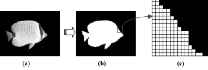
Fig. 1. Video object plane. (a) Texture. (b) Binary alpha component of the video object. (c) The 162 16 BAB.
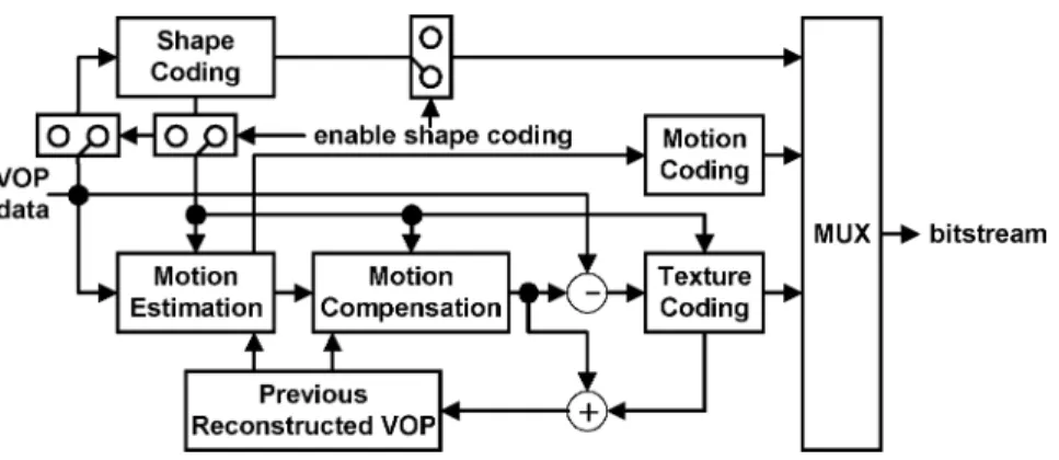
The MPEG-4 international standard [1], [2] treats moving pictures as an organized collection of visual objects and pro-vides several advanced techniques to access and represent the moving arbitrarily shaped natural and synthetic objects in video scenes. As shown in Fig. 1, a video object plane (VOP), which is the instance of a video object at a given time, is composed of an alpha component to define the object’s shape [Fig. 1(b)] and three color components (YCbCr) to render the object’s tex-ture [Fig. 1(a)]. MPEG-4 video encoding is based on the VOP encoder shown in Fig. 2. Basically, the VOP is defined as a min-imum rectangle that can cover the whole object. The size of a VOP at a given time for a video object depends on the shape of the video object at that time. That is, the size of the VOP for a video object is time-variant. For coding of the shape of a VOP, a bounding rectangle is first created and extended to multi-ples of 16 16 blocks with extended alpha samples set to zero. Shape coding is then initiated on a 16 16 block basis; these blocks are also called binary alpha blocks (BABs), as shown in Fig. 1(c). The alpha component of a VOP is encoded using a binary shape encoder while the color components are encoded using motion estimation and compensation (ME/MC) followed by DCT-based texture coding.
In an MPEG-4 binary shape encoder, a BAB may be en-coded in many different ways. If all of the pixels in a BAB are opaque or transparent, only the coding mode is encoded by means of a variable-length coder (VLC). In interframe coding, a BAB can be coded with reference to a suitable prediction BAB from the previous coded frame. This procedure is called binary motion estimation (BME). In this case, shape encoder encodes shape mode and motion vector by using VLC. Apart from those cases mentioned above, it is generally necessary to employ context-based arithmetic encoding (CAE) to the pixels within a BAB. There are two CAE operation modes: one is the INTRA mode and the other is the INTER mode. INTRA mode CAE exploits the spatial redundancy by estimating the proba-bility of the current pixel from its neighboring pixels. As for INTER mode, temporal redundancy is exploited by estimating 1051-8215/$20.00 © 2005 IEEE
Fig. 2. General structure of an MPEG-4 VOP encoder.
the probability of the current pixel from its neighboring pixels and from motion-compensated neighboring pixels of the pre-vious coded frame.
In intraframe coding, only INTRA mode CAE is performed. In interframe coding, both INTRA and INTER mode CAE are performed. In both modes, CAE operation is performed pixel by pixel in both horizontal and vertical raster scan order. Therefore, there are total four different coding processes: CAE ,
CAE , CAE , and CAE . At each pixel,
a template is formed. From the template, a context number is extracted and then used to access a probability table (the probability that the pixel is zero). The accessed probability and the value of the pixel are then used to drive an arithmetic encoder. In intraframe coding, the minimum size of the encoded
bitstream between CAE and CAE is chosen.
Similarly, the minimum size of the encoded bitstream among
CAE , CAE , CAE , and CAE
is chosen in interframe coding. In addition, the shape encoder may decide to encode subsampled versions (i.e., lossy coding) of BABs to save encoded bits. If this is the case, then the subsampling factor is also encoded into the bitstream. The BAB (subsampled or not) then undergoes CAE. Note that CAE itself introduces no additional loss. In summary, the MPEG-4 CAE algorithm requires a complex processing procedure and high-computation multiplicative operation while suffering severe data dependency.
Similar to MPEG-4’s predecessor, i.e., MPEG-2, ME/MC and texture coding are usually implemented by using dedicated hardware accelerators. Dedicated shape coding hardware is also recommended for higher MPEG-4 profiles and levels due to its high computing property [3], [4]. On the one hand, it is shown in [3] that shape encoding for test sequence weather with 10 frames per second (fps) QCIF (176 144) format re-quires 201.87 MIPS on an Ultra Sparc 2 workstation. On the other hand, [4] showed that CAE ranks the second place in and takes 19.61% of the total computation complexity of shape en-coding in a typical case of MPEG-4 application, i.e., 30 fps CIF (352 288) video sequences. Thus, we can roughly estimate that CAE for test sequence weather with 10 fps QCIF would re-quire 39.59 MIPS on an Ultra Sparc 2 workstation. Therefore, a software CAE implementation for 10-fps QCIF format could be feasible in principle on RISC or DSP platforms. However, the implementation of higher MPEG-4 profiles and levels on general purpose processors might not be feasible. For example,
CAE takes, respectively, 475.08 MIPS and 3263.40 MIPS for 30 fps CIF and 1920 1088 (main profile at level 4) video se-quences, respectively. In addition, the characteristics of bit-level operation and the strong data dependency of CAE also make it hard to be optimized in software implementation. Therefore, to fully utilize the compelling features of MPEG-4 brought about by shape coding, a dedicated hardware design for CAE is im-perative.
Several VLSI architectures for the whole MPEG-4 shape coding have also been presented [4]–[6]. For example, the whole shape encoder in [6] is set by a main processor through AMBA AHB bus and synchronized with the processor through interrupt. As for the hardware shape encoder design in [5], CAE takes more cycles (1,144 cycles) than full-search BME (1,072 cycles) in interframe coding. Furthermore, BME is not performed in intraframe coding. Therefore, CAE takes a major portion of the execution time in a hardware implementation. The reason why CAE dominates the performance of hardware shape encoder is that, although BME dominates the computing power of the shape encoder, it inherits the good parallelism property from motion estimation, and this property has already been well exploited for hardware design. In contrast, the com-plicated coding procedure and the strong data dependency of the CAE algorithm make it hard to exploit the pipeline and parallel facilities of CAE hardware design. Since MPEG-4 will be used in a variety of consumer electronics devices, such as video telephony, PDA, and cable boxes, there is a clear need of a cost-effective CAE VLSI architecture to encode shape information in real time.
The aforementioned compelling advantages of MPEG-4 shape coding and the awareness of the critical issues in de-signing high-performance and lost-cost shape encoder motivate us to explore a cost-effective hardware architecture for CAE. The contribution of this paper is the innovation of a cost-ef-fective, high-speed, multisymbol CAE architecture that can support MPEG-4 main profile at levels 3 and 4 under extreme and typical conditions, respectively. The designs for important implementation issues, including data preparation for contexts of multiple symbols, multiple probabilities lookup for these contexts, and the calculation of multiple multiplications for multiplicative arithmetic coding, are also presented.
The rest of this paper is organized as follows. Section II briefly reviews the related works on the design of arithmetic encoding. Section III presents a general introduction to the
MPEG-4 context-based arithmetic encoding. Section IV ex-plains the inherent characteristics of BAB and the numerical properties of the values of probabilities indexed by the contexts. The design space of multisymbol CAE is also explored in this section. Based on the information described in Section IV, a general multiple-symbol CAE architecture is explained first, and the experiment result of a particular two-symbol CAE implementation is shown in Section V. Finally, concluding remarks are given in Section VI.
II. RELATEDWORKS
To improve the performance of the arithmetic coding, some designs focus on the improvement of clock rate of the multipli-cation-free arithmetic coding [7]–[9], while other designs focus on parallel-processing multiple symbols within one clock cycle [11]–[14]. Most parallel designs focus on the improvement of the multiplication-free arithmetic coder, the Q-Coder [10]. In the original Q-coder proposed in [10], either a single more prob-able symbol (MPS) or less probprob-able symbol (LPS) is processed in one iteration. In [11], Feygin modified Q-coder architecture by employing loop unrolling and speculative execution of the inner loop of the arithmetic coding algorithm to achieve either a single LPS or multiple MPSs coding in one iteration. In [12], Jiang incorporated multiplication into the Q-coder coding oper-ation to achieve parallel arithmetic coding. Jiang’s architecture has a tree-structure processing element (PE) array, and each PE has its own renormalization operation. Furthermore, Jiang pro-posed a similar tree-structure parallel design for bilevel images to encode a group of input symbols within each cycle [13]. For input symbols with even number , their design requires PEs with a latency of cycles. In [14], Andra proposed a modification of the Q-coder by: 1) considering a two-symbol nonoverlapping window and not coding the second symbol if both of them are MPSs and 2) moving the majority of computations to the LPS path. This modification leaded to a 60%–70% reduction of the additions/subtractions with a loss of compression ratio about 1%–3% as compared to the original Q-coder. Andra’s design requires a state machine with 58 states while the Q-coder requires a state machine with only 30 states. In addition, the decoder has to make the corresponding changes to correctly extract the coded information.
In MPEG-4, it is necessary to initialize the arithmetic encoder prior to encoding the first pixel of each BAB and to flush/termi-nate it after encoding the last pixel of the BAB. Because these frequent initializations and terminations of the arithmetic en-coder are a source of inefficiency, a multiplicative arithmetic codec was chosen in preference to the less efficient shift-sub-tract type [15]. As for MPEG-4 CAE hardware design, Chang [5] proposed the delay line model to improve the context gen-eration of the design in [16], which employed barrel shifters to support the coding of subsampled BABs.
The aforementioned multisymbol designs for multiplicative arithmetic codecs either cause a significant hardware penalty resulting from employing straightforward loop unrolling and speculative execution of the inner loop of arithmetic coding al-gorithm or result in a loss of compression performance and the corresponding changes being made for the decoder arising from
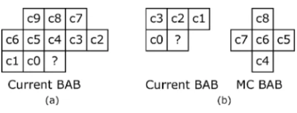
Fig. 3. (a) Current bordered BAB. (b) Bordered MC BAB.
Fig. 4. Templates for defining context. (a) INTRA template. (b) INTER template.
invoking the changes in the algorithm. In addition, all of the above designs do not discuss how to prepare the multiple bols and contexts for parallel processing. As the number of sym-bols grows, it becomes increasingly difficult to get input symbols, to extract contexts, to decide whether or not these symbols are suitable for parallel processing, and to process them in parallel with reasonable hardware cost and latency. In this paper, the above-mentioned challenges of hardware design will be efficiently resolved without the sacrifice of compression per-formance. In addition, the theoretical performance analyses of multisymbol CAE and the effects of renormalization are also re-vealed.
III. CONTEXT-BASEDARITHMETICCODING
This section gives a general introduction to the MPEG-4 con-text-based arithmetic encoding. The procedure for encoding a given pixel is as follows.
1) A context number is generated based on a template. 2) The probability of the symbol is indexed from a
proba-bility table using the context number.
3) The accessed probability and the value of the symbol are used to drive an arithmetic encoder.
To compute the context, the neighboring pixels of the symbol to be coded are used. Therefore, BABs and motion compen-sation (MC) BABs need to be padded with borders, as shown in Fig. 3, and the padding procedure can refer to the MPEG-4 Video Verification Model [17]. Fig. 4 shows the templates for INTRA and INTER CAE mode. The notation of “?” indicates the symbol to be encoded and is aligned with notation “c6” in INTER template. A 10-b context is generated for INTRA CAE mode while a 9-b context is generated in the same way for INTER CAE mode. The probability table contains the probabilities for a symbol being equal to zero. All probabil-ities are normalized to the range [1, 65 525]. Several registers, symbols, and constants are defined in Table I to further describe MPEG-4 CAE algorithm.
Fig. 5. Range update operation.
TABLE I
VARIABLES FOR THECAE ALGORITHM
Once the indexed probability is derived, it is used to drive an arithmetic encoder, which consists of range update and
renor-malization stages. The range update stage updates the range ( )
and the lower bound ( ) of the interval. The renormalization stage renormalizes when is smaller than QUARTER. This stage could also output the encoded bits of the arithmetic coder. Fig. 5 shows the detailed operations performed in the range up-date stage. If the input symbol is an LPS, would be updated to
rLPS and would be updated to a new position with an offset of the range of MPS (rMPS) from . If the input symbol is an MPS, would be updated to rMPS and would not need to be updated. According to the MPEG-4 standard, rLPS is computed as the product of the MSB 16 b of and cLPS. Thus, rMPS is calculated as R-rLPS.
Fig. 6 shows the operations performed in the renormaliza-tion stage that renormalizarenormaliza-tion is handled in three situarenormaliza-tions. In situation 1, where the interval [ , ) is within [HALF, 1), the arithmetic encoder needs to update and output one bit of 1 along with bits-to-follow. In situation 2, where the in-terval [ , ) is within [0, HALF), the arithmetic encoder needs to output one bit of 0 along with bits-to-follow. Other-wise, renormalization is handled in situation 3 where is up-dated and the count of bits-to-follow is increased. After the sit-uation is determined and the corresponding operation is per-formed, the lower bound and the range need to be enlarged by two times to complete the renormalization operation. Before en-coding the next symbol, the renormalization operation is per-formed iteratively until is no longer less than QUARTER. The CAE bitstream is generated according to the output bit and
Fig. 6. Renormalization operation.
the value of bits-to-follow, which is the number of the consec-utive occurrences of situation 3. Then the bitstream contains
bits-to-follow+1 bits that the value of the first bit is the same
as that of the output bit, whereas the value of each remaining bit is opposite to that of the output bit. For example, when the output bit is 1 and the value of bits-to-follow is 4, then the output bitstream would be a 5-b binary code 10 000.
IV. ANALYSIS ANDDESIGNSPACEEXPLORATION To understand the characteristics of BABs and CAE opera-tions, 11 test sequences listed in Table II are used for the sub-sequent statistics and analyses. Except for Dancer and Singer, these test sequences are from the MPEG-4 Video Verification Model [17]. All test sequences are generated for the core profile at level two with size conversion disabled and a shape refresh rate of 1:3. In MPEG-4 Video Verification Model, 8-b data are used to represent the alpha component of each pixel to indicate either 0 (opaque) or 255 (transparent). For a hardware design, the bi-level alpha data can be represented as 1-bit 0 or 1.
A. Multisymbol Context-Based Binary Arithmetic Encoding
Because the performance bottleneck of CAE is its sequen-tial processing nature, we explore both parallelism and hard-ware cost to gain an efficient design of multisymbol CAE. As mentioned in Section II, a multiplicative arithmetic encoding was chosen in preference to the less efficient shift-subtract type.
TABLE II
INFORMATION OFTESTSEQUENCES
Fig. 7. Examples of countingSo(n) in INTRA mode.
To minimize the hardware cost and the critical path delay of the multiplicative operations to achieve the encoding of tiple symbols within a clock cycle, the design of constant mul-tipliers is preferred. Therefore, only symbols with a particular set of context are chosen to be simultaneously encoded. We denote as a symbol whose context has either all-zero or all-one bits, as the occurrence of successive with the same context, and as the total symbol count of ,
i.e., . In addition, represents a
group of successive with the same context and can be processed simultaneously within the same clock cycle in our multiple-symbol CAE. Note that and also record the occurrence and the number of symbols that do not belong to . Fig. 7 illustrates examples for counting in INTRA mode. There are nine successive symbols whose contexts have all-zero bits, thus is increased by one. In the right-hand side of Fig. 7, there are three successive symbols whose context has all-one bits and therefore is increased by one. Be-cause each video object is a rigid body, the neighboring pixels around the coded symbol tend to be all zero or all one, i.e., should tend to appear in clusters, and this kind of situation would happen to the successive coded symbols. The following statis-tics also show this point.
Fig. 8 shows the distributions of and for those test sequences listed in Table II. Although dominates the occurrence count, has a proportion of 27% only. On the other hand, the total symbol count of has a proportion of 73%; this implies that tends to appear in clusters. For a rough estimation and comparison of CAE performance without
Fig. 8. Distributions ofSc(n) and So(n). TABLE III
CLPS VALUES FORS .
considering the renormalization effects and implementation is-sues, we assume that a baseline CAE can handle one symbol per clock cycle. Then the distribution of in Fig. 8 implies that the upper bound performance of a CAE that can handle
per clock cycle is approximately 0.635
cycles/symbol or 1.575 symbols/cycle, compared with a true two-symbol CAE that has a performance of two symbols/cycle. As for a CAE that can handle with arbitrary within one clock cycle, the speedup is about 2.95.
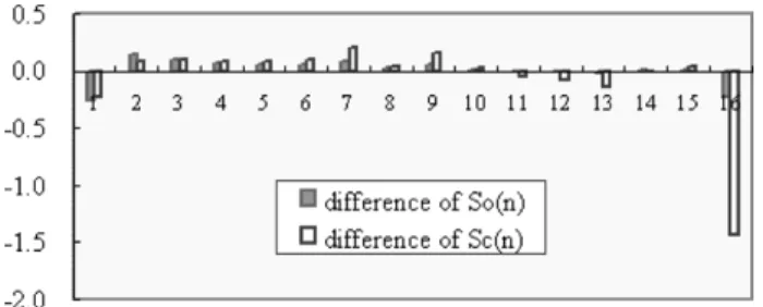
Fig. 9. Differences ofSo(n) and Sc(n).
Table III shows the cLPS values for in INTER and INTRA CAE modes. Binary representation of cLPS is replaced by signed-digit (SD) code when the cLPS in SD form has fewer nonzero digits. The mixed representation of cLPS can reduce the cost of the hardwired constant multipliers. Note that the values of cLPSs listed in Table III are quite small compared to those of other cLPSs.
B. Renormalization
As mentioned in Section III, renormalization operations start when is smaller than QUARTER and must be completed before the next symbol is encoded. In addition, renormalization operations for one symbol can be completed within either one or more clock cycles according to the implementation. From the statistics of the 11 test sequences, about 6.18% of coded symbols need to perform renormalizations, and about 0.76% of coded symbols that need to perform renormalizations belong to . This implies that the renormalization operations, and thus the renormalization strategies, affect the performance of proposed multiple-symbol CAE design quite little. This is reasonable because the values of cLPSs for are small and thus arithmetic encoder changes slightly when encoding ’s. Therefore, the renormaliza-tion occurs rarely when encoding ’s. Assuming that one iteration of renormalization operation takes one extra clock cycle to complete the encoding of a symbol and that the total CAE operation cycles of a BAB is the summation of the total symbol count and , which is the total cycle counts for renormalization, then the proportion of , defined
as , is about
10.34% of the total CAE operation cycles.
The differences of and shown in Fig. 9 are com-puted as
difference of proportion of proportion of difference of proportion of
proportion of
where and represent respectively
and with renormalization effect. The negative difference of implies that has less proportion than . Since renormalizations occurring at will break one with into several ’s, the total amount of ’s with increases. This results in a reduced proportion of . As illustrated before, renormalizations seldom occur at , and, even if renormalizations do
occur at , renormalizations break with large into ’s with smaller ’s most of the time. Therefore, the renormalization operations have very little effect on the performance of proposed multiple-symbol CAE design.
C. Design Space Exploration for CAE Coding
To design an efficient multisymbol CAE, three challenges must be conquered:
• extract multiple contexts of symbols and derive the prob-abilities of these contexts;
• have the critical path in range update operation; • achieve intersymbol dependency.
If we handle symbols with all kinds of contexts, we would re-quire multiple probability generators, e.g., either multiple prob-ability tables or a multiport probprob-ability table, and multiple mul-tipliers. From the fact that tends to appear in clusters, and this kind of situation would happen to successive symbols, we design a multisymbol CAE that can encode , a single , or a singe non- within one clock cycle. The proposed architecture significantly improves the performance and reduces the cost of both multiple probabilities generation and multiple-symbol range update unit.
Fig. 10 shows the proposed pipelined multisymbol CAE ar-chitecture. Both bordered current BAB and bordered MC BAB are stored in the Bordered BAB Buffer, and they can be read out one row or one column for horizontal or vertical scan, respec-tively. Context Generator contains two three-line buffers and can shift the data in the line buffers one or multiple positions to form the INTRA or INTER templates within one clock cycle. After completing the coding of one line of symbols, Context Gener-ator shifts out one line of symbols and reads in another line of symbols from Bordered BAB Buffer. A single context is fed into the probability lookup table (PLT) while multiple contexts are fed into a multiple symbol range update control (MSRUC) unit, to decide whether these symbols belong to . If there are symbols belonging to , Context Generator will shift the data positions, and these symbols will be handled in multiple-symbol range update (MSRU) unit. Otherwise, the Context Generator only shifts data one position and only one symbol will be handled in the range update (RU) unit. In both cases, when the updated is smaller than QUARTER, renor-malization operations start in the renorrenor-malization (RN) unit. The major differences between the coding paths of
and non- , i.e., a single or a singe non- , are the PLT/RU and MSRUC/MSRU.
As shown in Fig. 5, the critical path of updating the range includes the 16 16 multiplication, one 32-b subtraction, and one 32-b addition. This is not the case when it happens to en-code . Since the cLPSs for are small, hardware implementation for these multiplications is compact. Due to the small values of these cLPSs and the fact that domi-nates the total symbol count, it is possible to design a cost-ef-fective MSRU unit that can encode within one clock cycle without sacrificing the clock rate.
Before designing a particular MSRU unit, the potential speedup of different capabilities of the -MSRU unit that han-dles within one clock cycle is analyzed. In Fig. 11,
Fig. 10. Proposed multisymbol CAE architecture.
Fig. 11. Speedup of the multisymbol CAE that handles different numbers of symbols.
denotes the number of processed by the -MSRU unit in one clock cycle, and Speedup is defined as
, where and represent,
respectively, the operation clock cycles of the CAE with the RU unit only and the CAE with both the RU and -MSRU units.
Both and include cycles for
renormaliza-tion operarenormaliza-tions.
Recall that cLPSs for of INTER CAE are much smaller than those of INTRA CAE. This implies that the -MSRU unit would have a simpler architecture for INTER CAE part. There-fore, it is possible to design an MSRU unit that can handle for INTER CAE operation and for INTRA CAE operation to achieve a better performance/cost tradeoff. As mentioned in Section I, INTRA CAE operation is applied twice to BABs of intraframe (INTRA BABs) for vertical and horizontal scans; similarly, INTRA CAE and INTER CAE op-eration are both applied twice to BABs of interframe (INTER BABs). Thus, we can estimate the distribution of CAE opera-tion as follows:
The simulation result of the 11 test sequences shows that the count of INTER CAE operation has a proportion of about 34%. Fig. 11 shows the graph of speedup versus the number of sym-bols an MSRU unit can handle. The curve of INTER represents the speedup calculated for INTER CAE operation only. Simi-larly, the curve of INTRA represents the speedup calculated for INTRA CAE operation only. The curve of TOTAL indicates the statistics of combined INTER and INTRA CAE operation. Note that INTER CAE has better speedup than INTRA CAE.
In practical hardware designs, hardware cost and achievable clock rate are important considerations. Since cLPSs of are much smaller compared to cLPSs of other symbols, under the above considerations, it is feasible to add a range update accel-erator that deals with several within one clock cycle to the CAE design.
V. DESIGN OFMULTISYMBOLCAE
In this section, we focus on the detailed design of the major stages of the proposed multisymbol CAE architecture shown in Fig. 10. The major stages of this pipelined architecture are con-text generator, PLT/MSRUC, RU/RU2, and RN. The detail of this part is shown in Fig. 12. For simplicity, we focus on the explanation of the design of the two-symbol CAE architecture. However, the architecture can be easily extended to general mul-tisymbol CAE architecture for MPEG-4 shape coding. Note that RU2 control and RU2 shown in Fig. 12 correspond to MSRUC and MSRU shown in Fig. 10, respectively.
In Fig. 12, data in both bab buffer and mcbab buffer can be read out row by row or column by column for horizontal or vertical scan, respectively. In the Context Generator stage, line buffers, bab_lines and mcbab_lines, are used to generate INTRA and INTER templates. The counter register is used to in-dicate the position of these templates and to control how the data in line buffers are shifted. For a two-symbol CAE, this counter register is updated by one or two to indicate that one or two symbols have been processed. The bab_end flag is used by the bitstream generator to indicate the end of a vertical or horizontal scan of a BAB. In the stage of probability table lookup and RU2 control, proper context is selected according to the CAE mode. The selected context is then either fed to 1 K entries 16 b prob-ability table for INTRA mode or to a 512 entries 16 b proba-bility table for INTER mode. To handle within a clock cycle, extra pixels context_r are used to decide whether the two successive symbols, current symbol symbol_c and look-ahead symbol symbol_r, belong to . Flag cLPS_sel is used to indicate that all bits of contexts are all zero or all one. There are three major blocks in the range update stage: RU is the normal range update unit that handles one symbol at a time, RU2 is the range update unit that handles two symbols at a time, and RN deals with renormalization and bits output. All three blocks will
Fig. 12. Major stages of the proposed pipelined multisymbol CAE architecture. decide the requirement of renormalization after they complete the computation of the range. The whole pipelined stages are stalled when renormalization operation is processing. In the rest of this section, we will discuss the stall conditions and present the detailed design for context generation and range update unit. Although when renormalization occurs, when renormalization buffer is full, or when the BAB line buffers are not ready, the CAE kernel pipeline will be stalled, we will discuss the stalled conditions only caused by renormalization operations.
A. Pipeline Operation
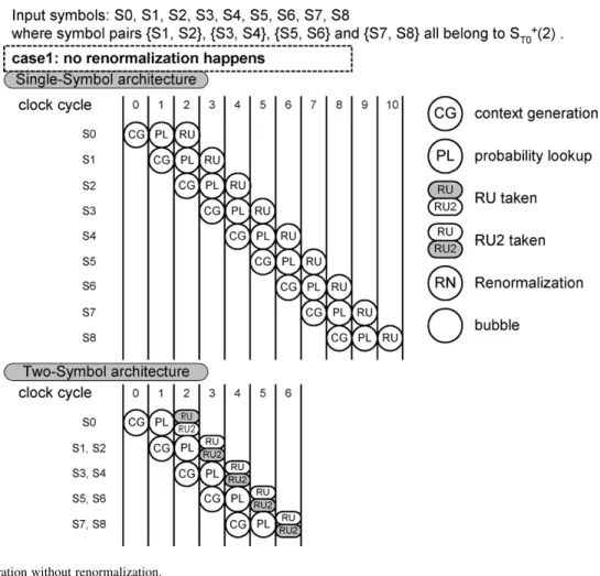
Fig. 13 illustrates the situation when no renormalization oc-curs among the input symbols. The symbol pairs {S1, S2}, {S3, S4}, {S5, S6} and {S7, S8} all belong to . The single-symbol architecture requires 10 cycles to encode these eight symbols, whereas the two-symbol architecture requires only six cycles. In this situation, the two-symbol architecture can save four cycles since there are four occurrences of two successive symbols belonging to . Fig. 14 shows the pipeline op-erations under different situations when the renormalizations are induced by different symbols. In these three situations, only S1 and S2 belong to . In case 2, the renormalization is induced by S0. In this situation, both single-symbol and two-symbol architecture take one extra cycle for renormalization.
However, one cycle is saved in the two-symbol architecture due to the occurrence of S1 and S2.
In case 3, the renormalization is induced by S1. Therefore, S1 and S2 cannot be encoded within a single cycle even though both S1 and S2 belong to . In such a situation, the two-symbol architecture does not have the advantage over the single-symbol architecture. Note that since the data in the line buffers would be shifted for two symbols when the RU2 control block detects two successive symbols belonging to , there must be registers to store the symbol and the cLPS of S2 for the second RU operation on S2. In case 4, S2 induces the renormalization. Both single- and two-symbol architecture require one more cycle for the renormalization. However, one cycle is saved in the two-symbol architecture due to the occur-rence of S1 and S2.
As evidenced by the statistics illustrated in the previous sec-tion, renormalization seldom happens to , and its effect on the performance only causes a little degradation. Together with the pipeline behavior just mentioned, the two-symbol CAE architecture can improve the performance most of the time when encoding two successive symbols that belong to .
B. Context Generation
As mentioned before, one of the challenges to design an ef-ficient multisymbol CAE is extracting the multiple contexts of
Fig. 13. Pipeline operation without renormalization.
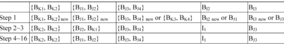
the coded symbols. Fig. 15(a) shows the required pixels to gen-erate two INTRA contexts for symbol and within a clock cycle. Virtually, this template will be shifted right by one or two positions respectively through the three line buffers shown in Fig. 15(b) when one or two symbols are encoded or it will be kept at the same position when the CAE is stalled or stopped. These line buffers (LB1, LB2, and LB3) are physically com-posed of four register chains for the movement of data. The first three register chains, rc1, rc2, and rc3, are used for border region, and their connection and control are almost indepen-dent of the number of symbols to be processed at a time. These three register chains are simple shift registers with control steps shown in Table V. Register is somewhat different because it may receive data from either of rc1 or of rc4. The rest of registers in these line buffers are mapped as
, , and
to form register chain rc4. Data in rc4 can be shifted either one or two positions. The control steps of generating contexts for symbol and are shown in Table IV. At the beginning of processing a BAB, three top rows of the BAB are loaded into these line buffers in parallel. After the end of encoding one row of the BAB, LB1 is loaded with new data again while data in LB2 and LB3 are already in the right positions. All of these load and shift controls can be easily implemented using a counter. To support 4 4 and 8 8 BAB sizes, the roles of , , , and are replaced by , , , , and , , , and , respec-tively. Though registers do not contribute much to the context generation and can be eliminated, we keep them to
TABLE IV
CONTROLSTEP FOR THEINTRA TEMPLATE
simplify the transpose design of reading data in either the hori-zontal or vertical direction from the Bordered BAB Buffer. The context generation of INTER CAE mode is similar to that of INTRA CAE mode.
C. Range Update Unit
As shown in Fig. 12, the range update stage includes three major function units: RU, RU2, and RN. RU shown in Fig. 16(a) is implemented in a manner quite like the range update operation introduced in the previous section, except that some stall con-trols are added. Since RU2 only deals with , it requires only four different types of constant multiplications with coeffi-cients shown in Table III. These multiplications are individually implemented in intra1 CU, intra0 CU, inter0 CU, and inter1 CU shown in Fig. 16(b), and the complete functionalities of these CUs are illustrated in Table VI. Since the RU2 deals with two symbols within one clock cycle, there are two CUs for each CU
Fig. 14. Pipeline operation with renormalization.
Fig. 15. Context generation for INTRA template.
TABLE V
CONTROLSTEP FORDATAMOVEMENT OF THEBORDERREGION
type. These CUs are implemented in carry-save adder architec-ture to save area and improve performance. Fig. 17 shows the implementation of RN. RN determines whether to output a one bit of 1 (out1) or 0 (out0) and it counts the bits_to_follow ac-cording to the range and lower bound when renormalizing them.
D. Experiment Result
The whole CAE design contains Bordered BAB Buffer, Context Generator, probability table and RU2 control block, range update unit, renormalization buffer, bitstream generator, bitstream buffer, and registers for control and status of the whole CAE design. We synthesize the whole CAE design from 20 to 90 MHz with Synopsys using TSMC 0.35- m 1P4M CMOS technology, the critical path is dominated by RU, and RU2 takes 9.17%–14.26% of the total area of CAE design. The renormalization buffer has a gate count of 982 for a size of 9
b 8 entries, 1 b for “code bit” and 8 b for bits_to_follow. In our current design, instead of using ROM and RAM, all of the tables are synthesized using combinational circuitry and all of the buffers are synthesized using registers. The design of these tables and buffers will be refined in the future.
Table VII shows the average clock cycles of CAE operation for different architectures. The average cycle is the time required for one CAE coding process. As mentioned before, two and four CAE coding processes are required for each BAB in intraframe and interframe coding, respectively. The bitstream with the min-imum size of the encoded bitstream of these coding processes is selected as the final output. The speedup is estimated by di-viding the average cycles of each type of architecture by that of proposed architecture with the two-symbol processing fea-ture. The results of the proposed architecture are derived from the Verilog simulation with the test sequence of Bream. Note that the purpose of the proposed architecture with single-symbol
Fig. 16. (a) RU implementation. (b) RU2 implementation.
Fig. 17. RN implementation.
processing capability is to demonstrate that the proposed archi-tecture can run at a higher clock rate than the designs in [5], [18], [19], while the purpose of the proposed architecture with two-symbol processing feature is to show that the proposed ar-chitecture has higher performance in terms of clock cycle count. Chou’s architecture [18] features its renormalization acceler-ation by using a lookup table to handle several renormalizacceler-ation operations within one clock cycle. Chang’s architecture [19], [5] features its elimination of redundant operations by stopping CAE operation when the size of the current bitstream of the vertical scan is larger than that of the horizontal scan. These features can also be applied to our architecture to achieve fur-ther improvement. The idea of redundant operation elimination is to terminate a current coding process when the bitstream size of the current coding process is larger than that of previous coding processes. Applying redundant operation elimination to our two-symbol architecture improves the average clock cycle count for each coding process from 194.65 to 180.33, i.e., a 7.83% improvement. The implementation of redundant operation elimination is simple. This mechanism requires one comparator for the bitsream size and the control circuit for terminating the current coding process and enabling the next coding process. The renomalization acceleration proposed
TABLE VI
FUNCTIONALITIES OFDIFFERENTTYPES OFCU
in [18] is to handle consecutive renormalization processes within one clock cycle. We have illustrated that the ideal case of this improvement is 10.34% for single-symbol architec-ture, discussed in Section IV-B. As for Chou’s architecarchitec-ture, renomalization acceleration has 4.72% improvement [18]. The implementation of renomalization acceleration is much more complex than that of redundant operation elimination. Furthermore, the authors of [18] did not clearly illustrate how to implement this improvement.
The gate count listed in Table VII contains the CAE major parts, i.e., context generation, probability lookup, and range up-date unit. All of these design are synthesized with the same tech-nology library, i.e., TSMC 0.35- m 1P4M CMOS. Note that the major parts of the proposed two-symbol architecture require a 12 447 gate count when synthesized at 40 MHz. The maximum clock rate of Chou’s, Wang’s, and our design are 72.5, 40, and 90 MHz, respectively. The layout and specification of the proto-typing chip for the whole CAE design are shown in Fig. 18 and Table VIII, respectively.
VI. CONCLUSION
In this paper, we have presented an efficient architecture design of multisymbol context-based arithmetic coding for MPEG-4 shape encoding. The important implementation issues, including data preparation for contexts of multiple symbols, multiple probabilities lookup for these contexts, and the calculation of multiple multiplications for multiplicative arithmetic coding, were all efficiently resolved in the proposed
TABLE VII
COMPARISONSAMONGDIFFERENTCAE ARCHITECTURES
Fig. 18. Specification of the prototyping chip. TABLE VIII
SPECIFICATIONS OF THEPROTOTYPINGCHIP
design. The key idea of our design is to exploit the inherent characteristics of BABs and the numerical properties of the probabilities indexed by the contexts. Data preparation of contexts for multiple symbols is efficiently solved by using four register chains. The design decision that CAE only encodes multiple symbols with the same context settles the issue of the generation of multiple probabilities of multiple symbols at a time and significantly reduces the cost of the probability table. Furthermore, the choice to encode multiple symbols with particular contexts greatly reduces the hardware cost and the required computation time for performing multiple multiplica-tion operamultiplica-tions within each clock cycle.
An example VLSI implementation of the proposed architec-ture that encodes two symbols within each clock cycle without sacrificing the clock rate can achieve a speedup of 1.47 in com-parison with traditional CAE architectures. Under the extreme
condition of encoding each boundary BAB in four coding pro-cesses (CPs), this two-symbol architecture can support Main Profile at Level 3 when running at 37.91 MHz (48 600 MB/s 4 CP/MB 195 cycles/CP 37.91 10 cycles/s). To sup-port Main Profile at Level 4 under similar conditions, the de-sign has to be able to run at 190.94 MHz. On the other hand, the simulation statistics over the 11 test sequences listed in Table II show that 13.9% and 10.2% BABs require two and four coding processes, respectively. To support MPEG-4 Main Profile at Level 4 shape encoding based on this criterion, the proposed two-symbol design has to be able to run at least 65.49 MHz
(489 600 MB/s (2 13.9% 4 10.2%) CP/MB 195
cycles/CP 65.49 10 cycles/s) for real-time MPEG-4 en-coding. The exact frequency at which the proposed design has to be able to run depends on the system overhead, such as data transfer of BABs and synchronization among functional units for the overall MPEG-4 encoding and other system function-ality.
The major parts of our design requires a 12 447 gate count when synthesized at 40 MHz, which is about 108.84% of the design proposed in [5], [19] and 72.94% of the design proposed in [18]. That is, the proposed two-symbol architecture has small area overhead. Note that the proposed architecture also has a higher maximum clock rate. The aforementioned hardware cost does not include the buffers. As shown in Fig. 9, the input buffer of CAE, called the BAB buffer, requires a 10 626 gate count, while the output buffer, called the bitstream buffer, requires a 6122 gate count. Unlike the major parts of CAE, the area of these buffers is less sensitive to the operating clock frequency. That is, the buffers could dominate the hardware cost of CAE. To have two simpler CAE encoders with single-symbol archi-tecture, the size of these buffers would be probably two times of that of the proposed two-symbol architecture. In addition, two
simpler single-symbol CAE encoders also require almost two times the area for the major parts of CAE. Therefore, the pro-posed design is a cost-effective solution for MPEG-4 Main Pro-file at Levels 3 and 4.
REFERENCES
[1] “Information Technology — Coding of Audio-Visual Objects,”, Switzerland, ISO/IEC 14 496–2, 2nd ed., 2001.
[2] N. Brady, “MPEG-4 standardized methods for the compression of arbi-trarily shaped video objects,” IEEE Trans. Circuits Syst. Video Technol., vol. 9, no. 6, pp. 1170–1189, Dec. 1999.
[3] P. M. Kuhn and W. Stechele, “Complexity analysis of the emerging MPEG-4 standard as a basis for VLSI implementation,” in Proc. SPIE
Vis. Commun. Image Process. (VCIP’98), Jan 1998, pp. 498–509.
[4] D. Gong and Y. He, “Computation complexity analysis and VLSI archi-tectures of shape coding for MPEG-4,” in Proc. SPIE VCIP’2000, vol. 4067, Jun. 2000, pp. 1459–1470.
[5] H.-C. Chang, Y.-C. Chang, Y.-C. Wang, W.-M. Chao, and L.-G. Chen, “VLSI architecture design of MPEG-4 shape coding,” IEEE Trans.
Cir-cuits Syst. Video Technol., vol. 12, no. 9, pp. 741–751, Sep. 2002.
[6] K.-B. Lee, N. Y.-C. Chang, H.-Y. Chin, H.-C. Hsu, and C.-W. Jen, “Optimal frame memory and data transfer scheme for MPEG-4 shape coding,” in Proc. IEEE Int. Conf. Consumer Electronics (ICCE), Jun. 17–19, 2003, pp. 164–165.
[7] M. Tarui, M. Oshita, T. Onoye, and I. Shirakawa, “High-speed imple-mentation of JBLG arithmetic coder,” in Proc. IEEE TENCON, vol. 2, 1999, pp. 1291–1294.
[8] Y.-T. Hsiao, H.-D. Lin, K.-B. Lee, and C.-W. Jen, “High-speed memory-saving architecture for the embedded block coding in JPEG2000,” in
Proc. Int. Symp. Circuits Syst. (ISCAS’02), vol. 5, Phoenix, AZ, May
2002, pp. 133–136.
[9] K.-K. Ong, W.-H. Chang, Y.-C. Tseng, Y.-S. Lee, and C.-Y. Lee, “A high throughput low cost context-based adaptive arithmetic codec for multiple standards,” in Proc. Int. Conf. Image Process., vol. 1, 2002, pp. 872–875.
[10] J. L. Mitchell and W. B. Pennebaker, “Optimal hardware and software arithmetic coding procedures for the Q-coder,” IBM J. Res. Dev., vol. 32, no. 6, pp. 727–736, Nov. 1988.
[11] G. Feygin, P. G. Gulak, and P. Chow, “Architectural advances in the VLSI implementation of arithmetic coding for binary image compres-sion,” in Proc. Data Compression Conf. (DCC ’94), 1994, pp. 254–263. [12] J. Jiang and S. Jones, “Parallel design of arithmetic coding,” Proc. Inst.
Elec.t Eng., pt. E, vol. 141, pp. 327–333, Nov. 1994.
[13] J. Jiang, “Parallel design of Q-coders for bilevel image compression,” in
Proc. Int. Conf. Parallel Distributed Syst., 1994, pp. 230–235.
[14] K. Andra, T. Acharya, and C. Chakrabarti, “A multi-bit binary arithmetic coding technique,” in Proc. Int. Conf. Image Process., vol. 1, Vancouver, BC, Canada, Sep. 2000, pp. 928–931.
[15] N. Brady, F. Bossen, and N. Murphy, “Context-based arithmetic en-coding of 2D shape sequences,” in Proc. Int. Conf. Image Process., vol. I, Santa Barbara, CA, Oct. 1997, pp. 29–32.
[16] D. Gong and Y. He, “An efficient architecture for real-time con-tent-based arithmetic coding,” in Proc. Int. Symp. Circuits Syst. (ISCAS
2000), vol. 3, Geneva, Switzerland, 2000, pp. 515–518.
[17] “MPEG-4 Video Verification Model Version 18.0,”, ISO/IEC JTC1/SC29/WG11 N3908, 2001.
[18] H.-L. Chou, “The design and implementation of MPEG-4 shape en-coding core,” M.S. thesis, National Chiao Tung Univ., Dept. Electron. Eng., Hsinchu, Taiwan, 2001.
[19] Y.-C. Wang, “Architecture design and implementation of MPEG-4 shape coding,” M.S. thesis, National Taiwan Univ., Dept. Elect. Eng., Taipei, Taiwan, 2001.
Kun-Bin Lee (S’02–M’05) received the B.S. degree in electrical engineering from National Sun Yat-Sen University, Kaohsiung, Taiwan, in 1996 and the M.S. degree in electronics engineering from National Chiao-Tung University, Hsinchu, Taiwan, in 1998, where he is currently working toward the Ph.D. degree in electronics engineering.
His current research interests include processor ar-chitecture, digital signal processing, and system-level exploration with focus on data transfer optimization and memory management for image and video appli-cations.
Mr. Lee is a member of Phi Tau Phi.
Jih-Yiing Lin received the B.S. degree in electrical engineering and the M.S. degree in electronics engineering from National Chiao-Tung University, Hsinchu, Taiwan, in 2000 and 2002, respectively.
She is currently with Sunplus Technology, Hsinchu. Her research interests include video signal processing, VLSI design, computer architecture, and system-level design methodology.
Ms. Lin is a member of Phi Tau Phi.
Chein-Wei Jen (S’78–M’84) received the B.S. de-gree from National Chiao-Tung University, Hsinchu, Taiwan, in 1970, the M.S. degree from Stanford Uni-versity, Stanford, CA, in 1977, and the Ph.D. degree from National Chaio-Tung University in 1983.
He is currently with the Department of Elec-tronics Engineering and Institute of ElecElec-tronics, National Chiao Tung University, Hsinchu, Taiwan, as a Professor. During 1985–1986, he was with the University of Southern California, Los Angeles, as a Visiting Researcher. His current research interests include VLSI design, digital signal processing, processor architecture, and design automation.