The Generation and Tracking of Mesh Objects in Image Sequences
Jui-Tai Ko, Bih-Wei Shyr, and Sheng-Jyh Wang
Department of Electronics Engineering, Institute of Electronics,
National Chiao Tung University, Hsin-Chu, Taiwan, R.O.C
Email address: shengjyh@cc.nctu.edu.tw
Tel:
+886-3-5731878 Fax: +886-3-5724361ABSTRACT
In this paper, we propose a new scheme that could automatically generate a hierarchical mesh structure for a real image and then use a nodal block matching to track this mesh structure in an image sequence. First, a three-layer pyramid is built by using a multi-resolution approach. For each layer, after extracting the high-curvature features, a linking procedure and a
spliuing process are applied to generate a compact set of representative points. By adopting the constrained Delaunay triangulation algorithm, the selected points can be triangulated into meshes. Starting from the coarsest layer to the finest
layer, we further eliminate the duplicate nodes and then form a hierarchical mesh structure. Based on the hierarchical mesh
structure and the intensity value at the mesh nodes and, we can progressively reconstruct an image with simple linear interpolation. Moreover, the motion of a mesh is tracked using a coarse-to-fine approach to lower the computational
complexity.
Keywords: Mesh object, Image representation, Delaunay triangulation, Mesh object tracking
1. INTRODUCTION
In computer graphics [5], a mesh representation has been used as a model and conveyed to various applications. How to
efficiently build a mesh model is one of the key technologies for these applications. In [7], an algorithm for generating a quadrilateral mesh from range data is proposed. Placing mesh nodes at beginning, the authors adjust the position of mesh nodes accordingly so that there are more nodes in curved regions and fewer nodes over smooth regions. Another mesh construction approach, which gradually deforms a primitive model to fit observed range data, can be found in [1 1].
However, the amount of data for these mesh-based applications are usually very large, especially when more details about
the objects are required. To cope with this problem, a h:ierarchical model is employed and the model can be displayed
optionally according to various requirements. A hierarchical mesh that adopts a node decimation procedure can be found in 16]. An approach that repeatedly subdivides a coarser model into a finer one has also been proposed in [8]. By using a mesh
representation as an object descriptor, different objects may have different mesh structures. Based on this concept, object
recognition can be done [9,10]. Even though there are so many applications that mesh can convey to, many researchers still
try to extend the usage of mesh. In the context of MPEG-4, a mesh is an alternative representation of an arbitrary shaped object and it may further be applied to object-based video coding. In [14], Y. Wang et al. evaluated a mesh-based motion estimation in an H.263-like coder. Among the object-based applications, "mesh" has attracted the attention of many researches and many methods have been proposed for the generating and tracking of meshes in video sequences. Once a mesh representation can be generated, it can be used for multimedia editing and video object manipulation—e.g., replace
objects in a scene, known as transfiguration [13]. Despite these applications relevant to MPEG-4, mesh is also used in image
analysis, like pattern analysis, depth estimation in stereo imaging, etc. To build mesh for real images, Y. Wang et al. proposed a snake-based method [1,2]. According to an energy function that is depending on reconstruction error, image gradients, and mesh connectivity constraints, they deform a regular mesh to generate a scene-adaptive mesh. Based on a
coarse-to-fine strategy, a hierarchical mesh is also generated. On the other hand, Tekalp et al. [15,16] developed a scheme to
generate a hierarchical mesh that can be used for video coding. By removing a special set of mesh nodes, namely an independent set, a finer mesh can be divided into two layers: a coarser mesh and the refinement data. Thus, a hierarchical
mesh can be built with a fine-to-coarse manner by repeating this node decimation procedure. Moreover, the discussions of avoiding patch overlapping and occlusion are also included.
2. BASIC CONCEPT
Our main concern is about how to generate a mesh to represent a real image. The desired mesh structure, same as others,
requires that the image surface within each patch can be approximaid by a plane. "Edge" is one kind of commonly used
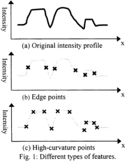
the locations where the edge features occur to form such a structure. However, this kind of mesh structure would introduce a complicated reconstruction problem when trying to recover the original image. There is a l-D examplein Fig. 1 to illustrate this problem. Fig. 1(a) is a given intensity profile. With the edge points shown in Fig. 1(b), it's fairly difficult to recover the original profile because we don't know how or where the intensity value transits from one level to another around the edge
feature. In this paper, we adopt a different type of feature —high-curvaturefeatures. A high-curvature feature indicates a
place where the curvature of the image surface changes dramatically. In fact, a step edge would have two high curvature features so that the position of the edge (between these two high curvature features) and the intensity information can be recorded at the same time. With the high-curvature points in Fig. 1 (c), we can do an easy reconstruction simply by using
linear interpolation.
(a)Original intensity profile X
i1
x XX
x
(b)Edge points xx • x X••X
: •. x
..x________
(c)High-curvature points XFig. 1 : Different types of features.
3. GENERATION OF STATIC MESH
The flowchart in Fig. 2 shows three basic procedures in our scheme. First, we extract high-curvature features for a given image. Generally, the number of detected feature points may be reduced to generate a more compact set of points.
They can be further linked into curves if some of them belong to the same boundary. Each linked curve is then
approximated by piecewise line segments. The two endpoints of these approximating segments would serve as the mesh
nodes. With them, we can thus generate a mesh object by using the constrained Delaunay triangulation algorithm.
Fig. 2: The flowchart of mesh generation
Image
3.1 EXTRACTION OF HIGH CURVATURE FEATURES
In this paper, we adopt the Jong-Wang operator [3] to extract the high-curvature features. This algorithm can accurately estimates both curvature magnitude and feature orientation. Based on some differential geometry analysis, the authors stated
that the principal curvatures of an image surface around the point (x, y) may be estimated by calculating the eigenvalues ofthe matrix
f(x,y) 2f(x,y)
M=
ax2 axiyf(x,y) 2f(x,y)
xy
where J(x,y)denotesthe image intensity. Given M, two eigenvalues and two corresponding eigenvectors are calculated at each location (x,y). 2
(x,
y) is the eigenvalue with larger magnitude. It indicates the maximum bending degree of theimage surface around the pixel (x,y). On the other hand, 2k.,
(x,
y) is the eigenvalue with lower magnitude. Itscorresponding eigenvector A, (x, y) would offer us the information about feature orientation. Fig. 3 shows an example
and illustrates the extracted high-curvature features.
\
I
(b)
Fig. 3 : (a) A synthetic image (b) Detected feature points
3.2 LINKING OF FEATURE POINTS
3.2.1 SIMILARITY MEASUREMENT
To link a curve, we apply similarity tests to decide whether two adjacent feature points belong to the same curve. The
tests take into account curvature strength. feature orientation, and some other constrains at the same time. Distinct test
generates its relative similarity score and the degree of simi larity can be measured as follows:
1) Ifthe curvature signs oftwo neighboring features are opposite to each other, they can't be linked together and S1 is set
to zero; otherwise, S1 is set to one.
I1 samesign
S ='
Iotherwise
2) The two neighboring feature points must have similar orientations. The test on the orientation of features is measured by S2 as: TD—DD
ifTD>DD
s2=
TDA
' 0 ' ' otherwisewhere TD1 is the threshold of the direction difference; DD is the direction difference; and A1 is an adjustable
scalar. If the direction difference of these two points is smaller than the predefined threshold, we get a nonzero score. If the direction difference is too large, S2 is set to zero.
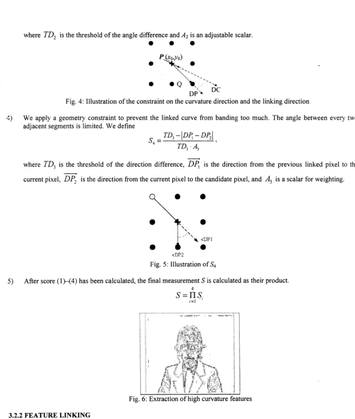
3) As shown in Fig. 4, we check the angle L DC, which is the orientation of A2 (x0, y0) and the orientation of DP, which links P and Q.Weset a limit on the angles between L DC and L DP and S3 is defined:
TD -ILDC-LDPI
TDA2
where TD2 is the threshold ofthe angle difference and A2 is an adjustable scalar.
S
•
•
P(.o,yo).
S •Q
DP'
DCFig. 4: Illustration ofthe constraint on the curvature direction and the linking direction
4) We apply a geometry constraint to prevent the linked curve from banding too much. The angle between every two
adjacent segments is limited. We define
=TD3
-D] -DP2
TD3 A3
where TD3 is the threshold of the direction difference, DP is the direction from the previous linked pixel to the
current pixel, DP, is the direction from the current pixel to the candidate pixel, and A3 is a scalar for weighting.
3.2.2 FEATURE LINKING
We wish the built mesh could retain the shape ofobjects. Hence, the high-curvature points around the object boundaries
are extracted first. After the extraction of feature points, we link these feature points into curves and then use the linked curves as constraints for the following Constrained Delaunay Triangulation process. Our linking strategies are stated as
follows:
1) Start at a pixel (p1),whose curvature measurement is larger than a predefined threshold.
2) Search the eight-connection points of the pixel and use the similarity measures to decide whether the candidate pixels
can be linked to the current pixel.
•
•
S
I
•
•
<DP2 Fig. 5: Illustration of S45) After score (l)—(4) has been calculated, the final measurement S is calculated as their product.
4
S
= 1I S t). •.i.. .cju4-
c-4I ? ? 1
I
3)
If
the length of a linked line is shorter than the chosen threshold, ignore the line and start to link another line. If thelength of the linked line is longer than the threshold, keep the line in the database. 4 Repeat Step 2 and Step 3 until no other features can be found.
3.3 SPLITTING METHOD
For an efficient representation. piece\ise line segments can be used to approximate these linked curves. Then. we only
need to recoid the endpoints of those line segments, instead of all the feature points on curves. We emplo\ a splitting
method described below to do curve approximation and Fig. 7 illustrates the splitting procedure. Given a curve as shown in Fig. 7(a). draw a straight line between the two end-points.
2) Compute the distance between the original curve and the approximated curve. If the maxima) distance is less than the
threshold, stop.
3 Otherwise,add an additional point at the place where the maximal distance occurs. Replace the segment with two new
segments. (Fig. 7(h). (co
)
Recursivel apply Step 2 and Step 3 to these new segments until the approximated curve is close enough to theoriginal curve. (Fig. 7(d))
p
Fig. 7: The procedure of the splitting method
The end-points of these piecewise line segments are used as the representative points of the linked curves. We use these points and their interconnections to perform Constrained Delaunay Triangulation to generate the mesh for the original image.
4. HIERARCHICAL MESH OBJECT GENERATION
A hierarchical mesh structure may have two major advantages: I) it can be transmitted progressively 2) it can facilitate the tracking of mesh. There have been many algorithms to construct a hierarchical mesh based on a coarse-to-fine strategy. Node decimation and edge or triangle collapse are commonly used in currently available algorithms. Once a mesh is built, those methods generate a rough estinlation of the mesh by removing unimportant nodes or by merging some similar patches. Since these procedures start from a finer resolution, the number of mesh nodes or patches is large at the first stage and the reioval of nodes or the merging of patches is very expensive. Besides, the features are usually cluttered. Such a fine-to-coarse method is easy to implement but is time-consuming. Opposite to these approaches. our procedure is a fine-to-coarse-to-fine scheme. We use a multi-resolution technique to build a three-layer pyramid. We generate a mesh for each layer and then eliminate duplicate mesh nodes to automatically form a hierarchical structure. In a fine-to-coarse strategy. all mesh nodes are tracked at the same time. After that, the motion vector of each node is transmitted accordingly based on which layer it
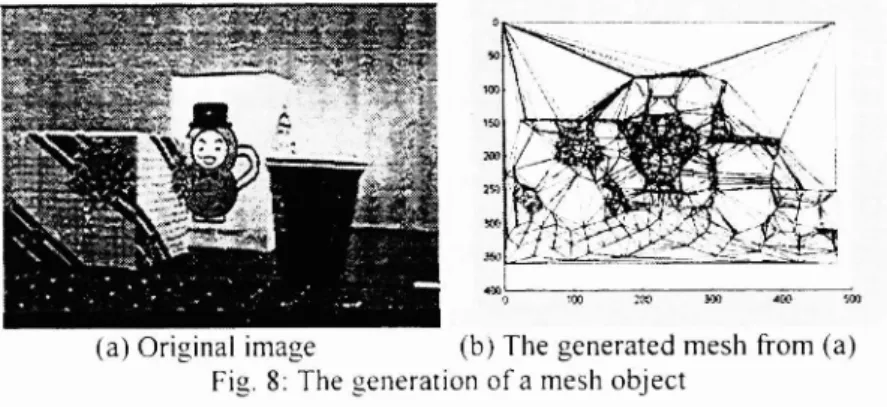
(a) Original image (b) The generated mesh from (a)
belongs to. On the contrary. a coarse-to-fine strategy divides a complicated problem (tracking all mesh nodes) apart to
reduce complexit. Mesh nodes on the coarser resolution layer are tracked first. These tracking results can help the tracking of mesh nodes on a finer layer. Because the movement on a coarser layer may offer a rough estimation, the motion vector on a finer layer can be found more efficiently.
In addition, a single-scale operator usually cannot extract all the features on various scales. In Fig. 8. it can be seen that the image is somehow over-segmented. To extract all the important features, a multi-resolution approach is employed to reduce computation complexlt\. Features appearing in coarser resolution are thought to be more important. and a multi-resolution approach has the inherent ability of importance classification. We can assign different degrees of importance on the generated nodes and edges. If the nodes are extracted from the lower resolution la\er. they are treated as more important and are assigned a larger weight. This hierarchical mesh structure may facilitate the motion estimation of the mesh obects. lhe steps of hierarchical mesh generation is briefly described as below:
Construct a three-layer pyramid b down-sampling the original image twice. 2j Extract the feature points on all three layers.
3) Foreach layer, link the feature points into curves and use piecewise segments to approximate them.
-I) Map the pixels on a linked curve to the corresponding pixels on the middle-resolution layer and mark these pixels
with higher weights.
5) Link the feature pixels at the middle-resolution layer into piecewise line segments. If the number of the pixels that are
marked higher weight (that means they ma he mapped from the lower-resolution layer) predominates the pixel
number of the line, mark this line with a higher weight. The lines that have no counterpart on the lower-resolution layer are marked with lower weights.
6) Repeat the above two steps on the highest-resolution layer. We classi the linked lines into three groups according to their weights. The lines with higher weights indicate they are extracted from the lower-resolution layers.
Based on the above procedure. we can generate the hierarchical mesh of an image. If we need the rough description of the image, ma only use the nodes and edges that are generated under the coarsest resolution. If we need a more detail view of the image. we use the nodes and edges generated in the higher-resolution layers. Fig. 9 shows the hierarchical mesh and the reconstructed intensity information.
(c) 1 he reconstruction results Fig. 9: An example ofa hierarchical mesh
5. TRACKING OF DYNAMIC MESH
So far, we have generated a hierarchical mesh to represent a still image. For an image sequence, it can be thought as deforming a mesh accordingly. We can record the trajectories of mesh nodes to represent those moving pictures. For this
purpose, a primitive, nodal block matching method is used to track the mesh nodes. Depending on feature locality, feature strength, and intensity, we search the best matching mesh node in the next frame. We benefit from the hierarchical meshes ofthe image frames, as mentioned before, to facilitate node tracking. The tracking steps are shown as follows.
1) Initially, perform the node tracking on the lowest-resolution layer by using a nodal block-matching method.
2) While tracking the current mesh, there are two cases:
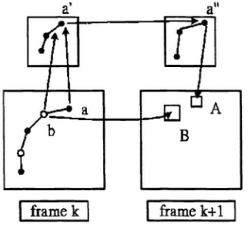
A. on the previous coarser layer, if there is one node (eg., a') that is mapped to the current node (eg., a), we can quickly and accurately track the current node a according to the motion of a'. In this example, we only need to
search within Area A to find the best matching pixel for pixel a.
B. Otherwise, the mesh node will be tracked directly by nodal block matching, like the point b in Fig. 10. 3) Repeat Step 2 until all the motion vector ofthe mesh nodes in the finest mesh have been found.
I
framek I
I framek-i-i IFig. 10: A hierarchical matching ofmesh nodes
In our experiments, we use the Claire sequence (288x360) as a test sequence. In Fig. 1 1 ,weshow the tracking results of
the first four frames. The left-hand side shows the original images (from top to bottom in increasing order) and the right-hand side shows the reconstructed images after tracking. Due to an inadequate number of mesh nodes and errors in the estimation of the motion vectors, the reconstructed images are a little distorted (see the face in Fig. 1 1 ). In practical, the
quality ofthe reconstructed images can be improved by increasing the number ofmesh nodes and some post-processing.
6. CONCLUSION
In this paper, we propose a different approach to generate hierarchical mesh objects. With this mesh structure, an image can be easily reconstructed back by simple linear interpolation. We also use a primitive method to track the generated mesh
object in an image sequence. The simulation result shows that the usage of the high-curvature features simplifies the
reconstruction process and the coarse-to-fine strategy may greatly reduce the complexity of motion tracking.
REFERENCE
1 . L. Y. Wang and A. Vetro, "Use oftwo-dimensional deformable mesh structures for video coding, Part Ii —The analysis problem and a region-based coder employing an active mesh representation", IEEE Trans. on Circuits and Systemsfor Video Technology, vol. 6, no. 6, pp. 647-659, Dec. 1996.
2. Y. Wang and 0. Lee, "Use of two-dimensional deformable mesh structures for video coding, Part I —Thesynthesis problem: Mesh-based function approximation and mapping", IEEE Trans. on Circuits and Systems for Video Technology, vol. 6, no. 6, pp. 636-646, Dec. 1996.
3. S.H. Jong, "The extraction of the high-curvature feature points in image surface", MS. thesis, National Chiao Tung University, Hsinchu, Taiwan, ROC, 1998.
4. J. R. Shewchuk, "Triangle: Engineering a 2-D quality mesh generator and delaunay triangulator", Applied Computational Geometry, pp. 124-133, May 1996, Philadelphia, Pennsylvania, also available at
http://www.cs.cmu.edu/guake/triangje.html.
5. James D. Foley, Andries van Dam, Steven K. Feiner, and John F. Hughes, Computer Graphics—Principles and Practice, 2nd in C, ADDISON-WESLEY.
6. K. Reinhard, "Mutiresolution representations for surfaces meshes based on the vertex decimation method", Comput. & Graphics, Vol. 22, No. 1, pp. 13-26, 1998.
7. Miguel Angel Garcia, Angel Domingo Sappa and Luis Basañez, "Fast generation of adaptive quadrilateral meshes from range images", Proceedings ofthe 1997 IEEE International Conference on Robotics andAutomation Albuquerque, New Mexico, April 1997.
8. Roberto Grosso, Christoph Lung, and Thomas Erti, "The multilevel finite element method for adaptive mesh optimization and visualization ofvolume Data", Proceedings of Visualization '97, pp. 387-394, 1997.
9. Mark Shackleton, "Learneddeformable templates for object recognition", lEE Colloquium on Genetic Algorithms in Image Processing and Vision, pp. 7/1 —7/6,1994.
1 0. Concettina Guerra, "2D object recognition on a reconfigurable mesh", Pattern Recognition, Vol. 3 1 ,No.1 ,pp.83-88, 1998.
1 1 . K.Hara, H. Zha, T. Hasegaa and T. Nagata, "3-D object modeling based on surface reconstruction and integration
using optima! polygonal approximation", IEEE International Conference on Computational Cybernetics and Simulation, Vol. 3, pp.2644-2649, 1997.
12. Cheng-Yuan Liou and Quan-Ming Chang, "Meshed snakes", IEEE International Conference on NeuralNetworics, Vol.
3,pp. 1516-1521, 1996.
13. Candemir Toklu, A. Tanju Erdem, and AM. Tekaip, "2-D mesh-based synthetic transfiguration ofan object with occlusion", IEEE International Conference on Acoustic, Speech, andSignal Processing, Vol. 4, pp. 2649-2652, 1997. 14. Y. Wang and Jörn Ostermann, "Evaluation ofmesh-based motion estimation in H.263-like coders", IEEE Transactions
on Circuits andSystemsfor Video Technology, Vol. 8, No. 3, June 1998.
1 5. Peter van Beek, AM. Tekaip, Ning Zhuang, Iil Celasun, and Minghui Xia, "Hierarchical 2-D mesh representation, tracking, and compression for object-based video", IEEE Transactions on Circuits and Systems for Video Technology, Vol. 9, No. 2,March 1999.
16. Yucel Altunbasak and A.M. Tekalp, "Occlusion-adaptive, content-based mesh design and forward tracking", IEEE
Left: The OriginalSequence Right:The Experiment Result Fig. 11: The tracking result for the first 4 frames of the Claire sequence