EXPERIMENT ON AN
APERTURE-COUPLED LEAKY-WAVE
ANTENNA WITH A PENCIL BEAM
Nien-An Kao,1Cheng-Chi Hu,1Jin-Jei Wu,2and Christina F. Jou11Institute of Communication Engineering
National Chiao Tung University Hsinchu, Taiwan, R.O.C.
2Department of Electric Engineering
Kao Yuan Institute of Technology & Commerce Luchu, Taiwan, R.O.C.
Recei¨ed 12 September 1998
ABSTRACT: A frequency-scanning leaky-wa¨e antenna with an aper-ture-coupled feeding structure is presented. The aperture-fed structure is used to excite the microstrip first higher mode. In order to suppress the dominant mode, we add a sequence of co¨ered wire in the center of this antenna. The measured H-plane main beam is a pencil beam, and is continuously scanned 12⬚ as the frequency¨aries from 9.85 to 10.27 GHz. This feeding structure is¨ery suitable for acti¨e phase antenna array applications.䊚 1999 John Wiley & Sons, Inc.
Mi-crowave Opt Technol Lett 21: 5᎐8, 1999.
Key words: leaky-wa¨e antenna; aperture-fed antenna; microstrip antenna
I. INTRODUCTION
Ž .
Recently microstrip leaky-wave antennas LWAs have been w x
the subject of extensive research 1 . The feeding structure is one of the important factors which determine the efficiency of the LAW. Here, we demonstrate an X-band LWA on one substrate, which is coupled to an open-ended microstrip line feed on another parallel substrate, through an aperture in the
Ž .
ground plane which separates the two substrates see Fig. 1 . The aperture-fed configuration has been proposed by Pozar w x2 , and it provides an excellent shielding between the feed
network and the radiation element. The radiation from the feed network cannot interfere with the main radiation pat-tern because of this separating ground plane. Because of this virtue, the feeding signal can be placed below the antenna, so that the whole circuit size can be reduced. In addition, using the LWA as the radiation element, the main beam can be a pencil beam, and can scan in the elevation plane with
vari-w x
able frequencies 3 . The microstrip LWA is not only a simple structure, but also has the advantages of easy fabrication, narrow beam, frequency scanning, and is very suitable for integrated antenna application. In this letter, the LWA is fed
w x from the aperture to excite the first higher mode 4 , leaks in the form of a space wave, and covered wires are added in the center of the microstrip LWA in order to suppress the
w x
dominant mode 5 . By controlling the frequencies of the feeding signal, the main beam can be scanned in the eleva-tion plane.
II. DESIGN OF THE APERTURE-COUPLED LEAKY-WAVE ANTENNA
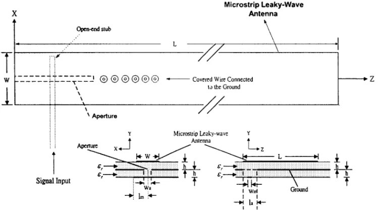
Figure 1 shows the structure of the aperture-coupled leaky-wave antenna. The antenna has to be fed in the center of one side to excite the first higher mode. A sequence of covered wire was inserted in the center of the antenna. The frequency of the leaky region is decided by the width of the antenna. The size of the aperture and the open-ended stub can be used to determine the antenna impedance. Here, a commer-cially available CAD tool IE3D is utilized to help us design
w x
the matching network 6 . The width of the open-end stub is determined to be the equivalent impedance of a 50 ⍀ mi-crostrip line at 10 GHz, and the aperture width is about 0.1g when the aperture length is decided to be close to 1.25 . Ing addition, the open-ended stub length is adjusted to match the input resistance of the antenna.
A prototype of the aperture-fed leaky-wave antenna is designed and fabricated on RTrDuroid substrate with sr 2.2 and a thickness of 20 mils. To excite the first higher mode,
Figure 1 Configuration of the aperture-coupled leaky-wave antenna. Ls 125 mm, W s 11.2 mm, s 2.2, h s 0.508 mm, l sr a
25 mm, was 2.02 mm, w s 1.54 mm, l s 17.06 mmm m
the dimensions of the LWA are determined to be 11.2 mm long and 125 mm wide. The aperture is of width was
Ž .
2.02 mm and length las 25 mm see Fig. 1 . A 1.54 mm wide microstrip line extends 17.06 mm past the aperture, and is termined as an open end.
The radiation characteristics of a microstrip LWA can be realized by obtaining its complex propagation constant  q j␣
Ž .
in the leaky radiation region, where is the phase constant and ␣ is the attenuation constant. We employed the rigorous
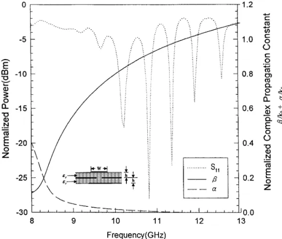
ŽWiener᎐Hopf solutions mentioned in 7 to obtain the com-. w x plex propagation constant. The variations of phase constant  and attenuation constant ␣ as a function of the frequency are shown in Figure 2. Figure 2 also shows the measured scattering parameter S11of our antenna, and we have found that the leaky region is narrow for this structure, which is about 600 MHz, at ; 9.85᎐10.45 GHz. The geometry and coordinate system for the microstrip leaky-wave antenna are shown in Figure 3. The guided wave will leak as a leaky mode
Figure 2 Normalized complex propagation constant and the S-parameter of the first higher mode for the microstrip leaky-wave
Ž .
antenna hs 0.508 mm, w s 11.2 mm, s 2.2, and k is the free-space wavenumberr 0
Figure 3 Geometry and coordinate system for the microstrip leaky-wave antenna. The width and the length of this antenna are 11.2 and 125 mm
MICROWAVE AND OPTICAL TECHNOLOGY LETTERS / Vol. 21, No. 1, April 5 1999
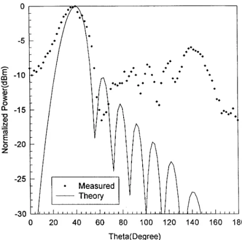
Ž .
Figure 4 Theoretical and measured far-field radiation patterns s 0 of the aperture-coupled leaky-wave antenna at 9.85 GHz
into the space wave and surface wave when  - k . is the0
elevation angle between the main-beam direction and the end-fire direction, and it can be calculated by using an
y1Ž .
approximation relationship of s cos rk . According0
to this relationship, it can be predicted that the main beam position will change with the frequency.
III. THEORETICAL AND EXPERIMENTAL RESULTS
Figure 4 shows the theoretical and measured radiation pat-terns of our aperture-coupled LWA at 9.85 GHz. The theo-retical prediction of the radiation pattern is calculated by
w x applying Huygens’ principle at the far-zone field 8, 9 .
Here, the aperture-fed leaky-wave antenna exhibits a tun-ing bandwidth from 9.85 to 10.47 GHz, and the variation of scanning angle is 12⬚. Figure 5 displays the measurement results of the main beam swings up from the end-fire
direc-Ž .
tion Z-axis as the operating frequency decreases from 10.47 to 9.85 GHz. The observed narrow beamwidth in Figure 5 is due to the attenuation constant ␣ decreasing when the
Ž .
operating frequency becomes higher see Fig. 2 . The maxi-Ž .
mum effective radiated power ERP of this antenna is ap-proximately 21.05" 0.7 dBm. The power level variation is due to the variation of the impedance of the aperture-fed LWA as the frequency varied.
IV. CONCLUSION
A technique utilizing the aperture-coupled structure for a leaky-wave antenna has been demonstrated in this letter. The structure provides a simple fabrication to achieve the tunable and narrow main beam, and the most important characteris-tic of eliminating the interference of the feed and the radia-tion elements. We found a measured beam-scanning angle
Ž .
Figure 5 H-plane y᎐z plane frequency-scanned radiation
pat-terns
of 12⬚. This antenna-feeding structure is very suitable for the applications of an active phase antenna array.
ACKNOWLEDGMENT
This work was supported by the National Science Council under Grant NSC88-2213-E-009-099.
REFERENCES
1. C.J. Wang, J.J. Wu, C.C. Hu, and C.J. Jou, Asymmetric feeding active leaky-wave antenna arrays, Microwave Opt Technol Lett 18 Ž1998 , 14. ᎐17.
2. D.M. Pozar, A microstrip antenna aperture coupled to a mi-Ž .
crostripline, Electron Lett 21 1985 , 49᎐55.
3. A.A. Oliner, A new class of scannable millimeter wave antennas, Proc 20th European Microwave Conf, Budapest, Hungary, Sept. 1990, pp. 95᎐104.
4. W. Menzel, A new traveling wave antenna, Proc 8th European Microwave Conf, 1978, pp. 302᎐306.
5. C.C. Hu, J.J. Wu, and C.F. Jou, An active frequency-tuned beam-scanning leaky-wave antenna, Microwave Opt Technol Lett 17 Ž1998 , 43. ᎐45.
6. Zeland Software Inc., IE3D user’s manual release 4.
7. A.A. Oliner and K.S. Lee, Microstrip leaky wave strip antennas, 1986 IEEE AP-S Int Symp Dig, pp. 443᎐446.
8. G.-J. Chou and C.-K. Tzuang, Oscillator-type active-integrated antenna: The leaky-mode approach, IEEE Trans Microwave
The-Ž .
ory Tech 44 1996 , 2265᎐2272.
9. C.A. Balanis, Antenna theory analysis and design, Wiley, New York, 1982.
䊚 1999 John Wiley & Sons, Inc. CCC 0895-2477r99
MODAL CIRCUIT DECOMPOSITION OF
LOSSY HOMOGENEOUS UNIFORM
QUASI-TEM COUPLED
TRANSMISSION LINES
J. A. Brandao Faria˜ 11Centro de Electrotecnia Teorica e Medidas Electricas
´ ´
Instituto Superior Tecnico´
1096 Lisboa Codex, Portugal
Recei¨ed 10 September 1998
ABSTRACT: This paper presents a detailed analysis and discussion of
the conditions on which the realizability of modal circuit decomposition for lossy homogeneous quasi-TEM coupled transmission lines stands. It is shown that the requirement of a real nonsingular modal transforma-tion matrix cannot always be met. With the exceptransforma-tion of some limit
( )
situations lossless conductors or¨ery high-frequency operation , equi¨ a-lent modal circuits can only be obtained, in general, for transmission-line configurations exhibiting¨ery peculiar symmetry properties.䊚 1999 John
Wiley & Sons, Inc. Microwave Opt Technol Lett 21: 8᎐11, 1999
Key words: multiconductor transmission lines; quasi-TEM analysis;
modal circuit decomposition
1. INTRODUCTION
Driven by the ever-expanding applications of VLSI, MIC, MMIC, and MHMIC structures, many papers devoted to the quasi-TEM analysis of multiconductor transmission lines have been published in the past decades. Among the many issues addressed, a considerable concern has been expressed about the conditions for the existence of realizable equivalent modal
w x
circuits 1᎐4 whose implementation via SPICE or other CAD w x
tools 5᎐6 permits easy simulation models for transient anal-ysis of n-coupled line circuits.
This paper presents a new contribution to the subject of modal circuits. Its purpose is to rigorously clarify the circum-stances under which lossy multiconductor lines may really be simulated by equivalent modal circuits.
2. MODAL DECOMPOSITION
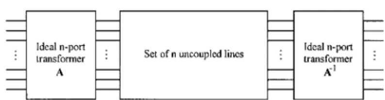
The equivalent modal circuit for a uniform n-coupled multi-conductor transmission line, depicted in Figure 1, is
com-.
Figure 1 The modal circuit is composed of: 1 an ideal n-port transformer with winding ratios chosen so that natural voltages and natural currents are transformed into modal voltages and modal
y1 t .
currents according to Vs TVmo daland Is T Imodal; 2 a set of n uncoupled transmission lines, each line being described by a given propagation constant␥ and by a given characteristic impedance Z ;w
.
and 3 a second ideal n-port transformer, identical to the first one, but with windings reversed, assuring the transformation Vmo dals Ty1V and Imo dals TtI
posed of two n-port ideal transformers with real transforma-w x
tion ratios and n uncoupled transmission lines 1 .
For determining the modal circuit constitutive parameters, we start with the well-known frequency-domain generalized
w x Telegrapher’s equations 7᎐8
¡
d2 d¡
Vs yZI Vy ZYV s 0 2 dx~
dx~
ª 2 Ž .1 d d Is yYV¢
dx¢
2Iy YZI s 0 dx Ž . Ž .where V x and I x are the column vectors of conductor voltages and conductor currents, respectively, and Z and Y are the impedance and admittance matrices per unit length, respectively. As usual, both Z and Y matrices can be broken down into their real and imaginary parts, that is, Zs R q jL and Ys G q jC, where R, L, G, and C are real symmetric positive-definite matrices.
The diagonalization of the ZY product, through a similar-ity transformation T, yields the diagonal matrix of eigenval-ues :
y1 Ž .
T ZYTs. 2a
The diagonalization of the YZ product, through a
similar-Ž y1t.
ity transformation T with Ti is T yields the same diago-nal matrix of eigenvalues:
y1 Ž .
Ti YZTis. 2b
Ž . Note that the matrix eigenvalue equation in 2b is not
Ž .
independent of 2a as, in fact, one equation is just the transpose of the other. It should be added, further, that ZY
y1Ž .
and YZ are similar matrices since ZYs Y YZ Y.
As for the modal circuit shown in Figure 1 we have, on the one hand, that the evaluation of the transmission matrix A for the n-port ideal transformers is based on the knowledge
w x of T and T 1 viai
T 0
As y1t
0 T
and, on the other hand, the set of n uncoupled lines is characterized by a diagonal matrix ␥ of modal propagation
1r2 w x
constants, given by␥ s 7 , and by a diagonal matrix Zw Ž .y1 of modal characteristic impedances given by Zws T␥ ZTi w x7 .
MICROWAVE AND OPTICAL TECHNOLOGY LETTERS / Vol. 21, No. 1, April 5 1999