行政院國家科學委員會補助專題研究計畫簡易報告
一個平行化耦合
DSMC-NS 模擬程式的精進與通用化及其應用之研究(三年)
Improvement and Generalization of a Parallelized Hybrid DSMC-NS Code
and Its Applications (3 Year)
計畫類別:;個別型計畫 □整合型計畫
計畫編號:NSC-96-2628-E-009-136-MY3
執行期間:96 年 08 月 01 日至 99 年 07 月 31 日
計畫主持人:吳宗信
計畫參與人員:洪捷粲、許哲維
本成果報告包括以下應繳交之附件:
□ 赴國外出差或研習心得報告一份
□赴大陸地區出差或研習心得報告一份
□出席國際學術會議心得報告及發表之論文各一份
□國際合作研究計畫國外研究報告書一份
執行單位:國立交通大學機械工程學系
中 華 民 國
97 年 05 月 30
行政院國家科學委員會專題研究計畫期中報告
一個平行化耦合
DSMC-NS 模擬程式的精進與通用化及其應用之研究(第一
年
)
Improvement and Generalization of a Parallelized Hybrid DSMC-NS Code
and Its Applications (First Year)
計畫編號:NSC-96-2628-E-009-136-MY3
執行期限:96 年 08 月 01 日至 97 年 07 月 31 日
主持人:吳宗信 國立交通大學機械工程學系
計畫參與人員:洪捷粲、許哲維
中文摘要
許多重要問題的流場通常包含連續流
體與稀薄氣體的區域. 對於這些問題的數
值模擬無法僅考慮單一連續流體或分子動
力學的方法來解決. 同時包含連續流體與
分子動力學的複合法通常可用來解決這樣
的問題. 在這三年的計畫裡, 我們將改進先
前所發展的平行化複合直接模擬蒙地卡
羅-那威爾史托克法的程式. 在第一年的計
畫裡, 我們已經改寫三維平行化直接模擬
蒙地卡羅法的程式為一泛用型的程式碼,
可模擬二維, 二維軸對稱, 以及三維的問題.
除此之外, 我們也利用直接模擬蒙地卡羅
法取樣的技術詳細的探討二維超音速流體
流經一角度為
25 度的楔形物的動力學以
了解失效參數的分布, 尤其是邊界層內部.
目前發現即使速度梯度相當大, 大多數邊
界層內的速度分布仍處於熱平衡狀態. 我
們提出一改良複合演算法以替代先前的程
式. 此改良演算法的相關議題將於此報告
中討論.
關鍵字: 平行化直接模擬蒙地卡羅法, 複合直接 模擬蒙地卡羅-那威爾史托克法, 動力學研究Abstract
Several important flow problems often involve continuum and rarefied regions in the flow fields. Numerical simulations of these flows can not be done properly alone using either continuum or particle method. Hybrid of continuum and particle methods is often required to properly resolve the flow fields. In
this 3-year project, we proposed to refine and improve our previously developed parallelized hybrid DSMC-NS code. In the first year, we have converted the 3-D PDSC (Parallelized Direct Simulation Monte Carlo Code) into a general-purpose DSMC which features 2-D, 2-D axisymmetric and 3-D functionalities. In addition, a detailed kinetic study in a supersonic flow past a 2-D 25-degree wedge flow, which utilizes the DSMC sampling technique, is used to understand the distribution of breakdown parameters, especially in the boundary layers. We have found that the velocity distribution in most of the boundary layr region is in thermal equilibrium, even the velocity gradient is very large. A preliminary improved hybrid algorithm was then proposed to replace the previous version of hybrid one. Some issues related to this improved algorithm are discussed in this report.
Keywords: parallelized DSMC, hybrid DSMC-NS
code, kinetic study.
1. Introduction
Several technically important flow problems often involve continuum and rarefied regions in the flow fields. Examples include expanding reaction control system plumes from a space vehicle2,3), hypersonic
flows past a blunt body4), expanding plumes from a
rocket at high altitude5), high compression ratio
turbomolecular pump6) and jet-type chemical vapor
deposition7), to name a few. Unfortunately, neither
continuum nor rarefied flow solver can be used alone to accurately and efficiently solve the entire flow field. Thus, how to efficiently and accurately simulate this kind of flows represents a great challenge to the computational fluid dynamics community at large.
Prior studies in solving flow fields involving continuum and rarified regions employed the hybrid DSMC-NS schemes with various approaches of
coupling the particle and continuum methods. Detailed reviews of these approaches can be found in Schwartzentruber and Boyd8-9) and Wu, et al.1) and
references cited therein. In general, a hybrid DSMC-NS method applies the concept of spatial domain decomposition to distinguish the computational domain of rarefaction or thermal non-equilibrium to be modeled by the DSMC method, and the computational domain of continuum to be solved by the CFD (NS, Euler or Stokes) solver. Success of such hybrid numerical method relies upon four important issues1): 1) Accurate and efficient method in
determining the breakdown region; 2) Proper and efficient flow properties exchange at breakdown interface; 3) The effect of steadiness of the flow solution on designing data exchange at the interface; 4) Proper detection of coupling convergence. In the present paper, we focus on the first and fourth issues that can further improve the efficiency of the hybrid DSMC-NS algorithm.
Wu, et al.1) has developed a parallelized hybrid
DSMC-NS scheme with unstructured grids, in which a continuum breakdown parameter10) (Kn
max=
max[KnD, KnV, KnT]) where KnQ=|∇Q|×λ/Q and a
thermal non-equilibrium indicator (PTne=|(Ttr-Trot)/Ttr)
were used to determine the continuum and thermal equilibrium breakdown regions, respectively. A domain overlapping strategy, taking advantage of unstructured data format, with Dirichlet-Dirichlet type boundary conditions based on these two breakdown parameters is used iteratively to determine the choice of solvers in the spatial domain. These breakdown regions were simulated using the more expensive DSMC method, while other regions were simulated using the relatively cheaper NS equation solver. Normally, the size of the overlapping region is about 2-3 layers extending from the particle side towards continuum side to make sure the Maxwellian distribution can be applied accurately at solver-solver boundaries. Results showed that, not only the leading edge and shock, but also the boundary layer regions are identified as breakdown regions, in which large velocity gradient due to high-speed flows is often the dominating factor in determining Knmax.
In brief summary, there are still several issues, which require further investigation. First, the inclusion of the boundary layer as the continuum breakdown region often caused slow convergence or even wrong solution of the coupling, which was also found by Schwartzentruber and Boyd11). Now
question arises: is it truly continuum breakdown in the whole domain of boundary layer? Second, no automatic convergence mechanism of the coupling was tested, which is important in practice. Only constant number of iterations in both NS and DSMC were employed to obtain the final coupling solution.
Third, the computational cost could be higher than
the pure DSMC solution mainly due to the expensive DSMC simulations for several couplings. Any
strategy of reducing the computational cost of DMSC should be highly welcome. This issue has been addressed by Schwartzentruber and Boyd8-9) by using
so-called “sub-relaxation” scheme in DSMC sampling and will not be discussed here. In this paper, we intend to address the first two issues and hopefully we can improve the hybrid DSMC-NS algorithm to become a more practical tool in simulating flow field involving continuum and continuum/thermal equilibrium breakdown regions, such as hypersonic flows.
The present midterm report is organized as follows. Direct kinetic velocity sampling from a pure DSMC simulation for a supersonic nitrogen flow past a 2-D wedge flow is described in detail in Section 2. Improved hybrid DSMC-NS algorithm is then proposed in Section 3, emphasizing the modifications as compared to the original version1), which include
the definition of a new breakdown parameter, the “adaptive” overlapping strategy in applying this new breakdown parameter, and an automatic convergence mechanism for NS solver. This improved algorithm is then verified in detail in Section 4 by simulating a supersonic nitrogen flow past a 25-degree wedge, including the highly rarefied wake behind the wedge. Finally, in Section 5, the conclusions of the present study are summarized along with several possible future directions of research.
2. Kinetic Velocity Sampling
As mentioned earlier, we would like to know whether the boundary layer is a thermal non-equilibrium region or not. We thus conduct a through direct kinetic sampling study in a supersonic nitrogen flow past a 25-degree wedge the same as the previous one1). This test problem represents an idealistic flow
for studying the continuum and thermal breakdown parameter since it includes a leading edge near the tip of the wedge surface, an oblique shock wave originating from the leading edge, a boundary layer along the wedge surface, an expanding fan starting at the end of wedge surface, and a highly rarefied wake behind the wedge. Sampling locations and distribution of continuum breakdown parameter Knmax based on
gradients of flow properties (density, temperature, velocities) and local mean free path, resulting from a pure DSMC simulation, are indicated in Fig. 1. Important flow conditions are briefly summarized for clarity. They include: Mach number of 4 (1,111m/s), free-stream temperature of 185.6K, wall-temperature of 293.3K. DSMC related simulation conditions are the same as those described earlier1). Note the
Knudsen number based on the length of the wedge and the free-stream conditions is 0.0017. In addition, the thermal non-equilibrium indicator is further generalized in the present study as follows:
) 3 ( ) 1 T T ( ) 1 T T ( ) 1 T T ( ) 1 T T ( ) 1 T T ( P v rot 2 tot v v 2 tot rot rot 2 tot z 2 tot y 2 tot x * Tne ζ ζ ζ ζ + + − + − + − + − + − =
(1)
where Tx, Ty and Tz are translational temperature in the
x-, y-, z-direction, respectively. Trot, Tν and Ttot are
rotational, vibrational and overall temperature, respectively. ζrot and ζν are the number of degree of
freedom of rotation and vibration, respectively. Totally 52 points in the regions, including near leading edge, oblique shock, boundary layer and expanding fan, are selected. Velocity distributions of three Cartesian directions at each selected point are sampled for particles up to at least 0.3 million, and then are compared with the corresponding local Maxwell-Boltzmann velocity distributions to understand the degree of continuum breakdown in these representative points. In addition, the thermal non-equilibrium indicator *
Tne
P is also calculated at each selected point from the DSMC simulation. In general, the KnD and KnT dominates the most part of
the computational domain and across the oblique shock, respectively, while KnV dominates near the
solid wall due to the high velocity gradient in the boundary layer and wake regions. Only typical results of the kinetic velocity sampling in regions in the boundary layer are described in the following in turn. Other regions such as those near the leading edge, across the oblique shock and expansion fan are skipped due to the limited number of paper pages.
Figs. 2b-2d and Figs. 3b-3d show the random velocity distributions at Points 26-30 and Points 31-35 near the boundary layer, respectively, along with the local Maxwell-Boltzmann distribution. Note that Points 26-30, as compared to Points 31-35, are at locations closer to the leading edge, which are expected to have larger property gradients. As shown in Fig. 1 in both regions in the boundary layer, very large breakdown parameter Knmax occurs due to the
large velocity gradient, especially near the solid wall (Knmax>0.4). Normally these two regions in the
boundary layer would be considered as continuum breakdown domains based on previously proposed criterion of Knmax. Astonishingly at first, at Points
31-35 the velocity distributions are in very good agreement with the local Maxwell-Boltzmann distribution and the temperature variation among different degrees of freedom is very small, even with very large value of Knmax (all higher than 0.05 as
shown in Fig. 1). At Points 26-30 that are closer to the leading edge, the velocity distributions are also in excellent agreement with the local Maxwell-Boltzmann distribution, although the temperature in both x- and y-direction begins to deviate from the average temperature. Even at Point 30, which is very near the solid wall, the maximum temperature deviation to the average temperature is less than 5-6% ( *
Tne
P =0.034). In addition, at Points 31-35, which is
further downstream in the boundary layer, not only the velocity distribution agrees very well with the local Maxwell-Boltzmann distribution, but also the temperature deviation among the various degrees of
freedom is very small. Even at Point 35 that is very close to the solid wall, the maximum temperature deviation is less than 3% ( *
Tne
P =0.018). We attribute the non-breakdown of continuum and thermal equilibrium among various degrees of freedom to the fact that the particles frequently collide with the isothermal solid wall and are thermalized to the wall temperature before emitting into the region near the wall.
In Fig. 1, the continuum breakdown parameter
Knmax in the boundary layer region is higher than .
Thr max
Kn =0.05 recommended by Wang and Boyd10).
That means the boundary layer regions would be assigned as the breakdown regions. However, it can be found the random velocity distributions in the x-, y-,
z-direction agree excellently with the
Maxwell-Boltzmann distribution, respectively, in Figs. 2b-2d. Furthermore, the value of *
Tne
P are lower than 0.0185
for all of the Point 31-35. Thus, we can conclude that the degree of the continuum breakdown in the locations, such as Point 31-35, is overestimated based on the previous criterion of Knmax. The above kinetic
studies indicate that it is not necessary to utilize the DSMC method in the whole boundary layer region, even the continuum breakdown parameter Knmax is
very large. This observation is critical in improving the efficiency of a hybrid DSMC-NS algorithm presented in Section 3.
In brief summary, the detailed kinetic velocity sampling proves that previous defined continuum breakdown parameter Knmax can generally predict the
continuum breakdown well, except in the region of the boundary layer, where the thermal equilibrium generally holds well. In this region, the NS solver can solve flow field efficiently and accurately with proper velocity slip and temperature jump boundary conditions. Previously, we have found that inclusion of this boundary layer region as the DSMC domain may slow down the convergence of coupling1). Thus,
an alternative continuum and thermal-equilibrium breakdown determining strategy is required to effectively “exclude” this boundary layer region to generalize the proposed hybrid DSMC-NS algorithm.
3. Improved Hybrid DSMC-NS Algorithm
In the previously proposed hybrid DSMC-NS algorithm using unstructured grids1), steady-state
flow calculation is assumed. Two breakdown parameters were used to identify the breakdown region. On is the continuum breakdown parameter, while the other is the thermal-equilibrium breakdown parameter as defined earlier in Section 1. General procedures of iterative coupling between DSMC and NS solvers are summarized as: 1) Simulate the whole domain using the NS solver; 2) Determine the breakdown regions based on distribution of breakdown parameters Knmax and P ; 3) Extend the Tne* breakdown domain towards continuum domain; 4) Simulate the breakdown domain using the DSMC
solver; 5) Obtain the new breakdown domain based on the coupled solution from NS and DSMC solvers;
6) Repeat Step 1) (but only for the continuum domain)
through Step 5) until convergence.
In the present paper, we use the UNIC-UNS NS solver12,13), instead of the HYB3D14) as used in our
previous study1). The present Navier-Stokes solver,
developed by Chen and his coworkers12,13), employs
the cell-centered finite-volume method with a hybrid 2D/3D unstructured-grid topology. Details of various numerical and physical modules embedded in this solver can be found in [12, 13] and are skipped here for brevity. Only three important features are mentioned here. The first is the use of pressure-based method, which allows accurate simulation of the flows at all speeds. The second is the automatic slip velocity and temperature jump boundary conditions near solid wall. The third is parallel computing of the NS solver also incorporates the graph-partition tool, PMETIS15), which is the same as that in the
parallelized DSMC solver16-18) (PDSC).
As mentioned earlier, by applying the Knmax as the
breakdown parameter in addition to the thermal non-equilibrium indicator *
Tne
P , the boundary layer region
is generally included as the breakdown DSMC domain for high-speed flows, which generally slows down the convergence of the coupling between two numerical solvers. In the present study we define a new continuum breakdown parameter Knp to replace
the role of Knmax as follows,
p
Kn p p
λ
= ∇ (2)
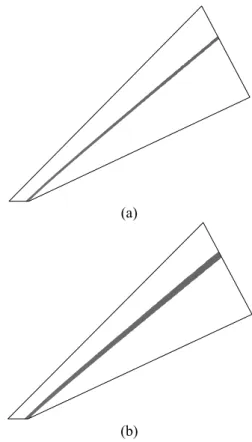
For example, Fig. 4 shows the initial breakdown domains using the new breakdown parameter (Knp>0.05) based on the solution of initial NS
simulation. With this new breakdown parameter, most of the boundary layer can be excluded as one of the breakdown regions, in which the more efficient NS solver can solve flow field with proper slip boundary conditions at wall. However, this may induce another slow convergence of coupling using the previously proposed hybrid DSMC-NS algorithm. The reason is that, from the initial whole-domain NS simulation, we are not able to detect the thermal non-equilibrium near the leading edge since the UNIC-UNS is a single-temperature NS solver like most of the NS solvers. This results in a very small breakdown region, based on the Knp, along the
boundary layer near the leading edge. In the present study, we extend the breakdown interface 25 overlapping layers toward continuum side along the boundary layer.
In addition, previously we always restarted the DSMC simulation from quiescent or uniform flow field in each coupling. In the present study, instead we take the previous coupled solution as the initial guess of the DSMC to decrease the computational time of DSMC simulation. From our experience, this will save some time but not much.
In brief summary, general procedures of new proposed hybrid algorithm are summarized as follows: 1) Simulate the whole domain using the NS solver; 2) Determine the breakdown regions based on distribution of breakdown parameters, Knp and P ; Tne*
3) Estimate the location of thermal breakdown
interface by extending more layers near in the direction of boundary layer; 4) Extend the breakdown domain towards continuum domain; 5) Simulate the breakdown domain using the DSMC solver; 6) Obtain the new breakdown domain based on the coupled solution from NS and DSMC solvers; 7) Repeat Step 1) (but only for the continuum domain) through Step 6) until convergence.
4. Results and Discussion
4.1 Flow and Simulation Conditions
Similar to previous study1), a supersonic flow (M=4)
past a 2-D wedge of 25° half-angle with a length of 60.69mm is chosen as the test problem for the new hybrid algorithm. All simulation conditions are the same as those in previous study and are thus not repeated here. In this study, number of extension layers is fixed as two, except near the boundary layer close to the leading edge. Some of the simulation conditions will be mentioned in the following, as it is necessary.
4.2 Distribution of Breakdown Domains
The final distribution of breakdown domains using
Knp and P after 20 coupling iterations is illustrated Tne* in Fig. 5. Note the criterion for Knp and P is set as Tne* 0.05 and 0.03, respectively, in this study, unless otherwise specified. Note the breakdown domain only include the regions across the shock and regions near the leading edge, in which most boundary layer regions are excluded, which the NS equation solver can be used obtain the flow field more efficiently.
4.3 Comparison of the Hybrid DSMC-NS Algorithm with the Pure DSMC Method
Fig. 6a and Fig. 6b compares contour distributions of density and translational temperature obtained from the pure DSMC simulation and the new hybrid DSMC-NS algorithm, respectively. The results of the present hybrid algorithm are in excellent agreement with those of pure DSMC simulation. Detailed comparisons of density, velocity magnitude and temperature profiles obtained from the present hybrid algorithm, pure DSMC and pure NS solvers are also very favorable, but they are not presented in the present paper due to the limitation of paper length. They will be presented elsewhere in the near future.
4.4 Comparison of Convergence between the Old and New Hybrid Algorithms
Table 1 summarizes the simulation conditions along with the breakdown criteria for the old and new hybrid algorithm for this specific case. Results show that fewer DSMC cells are included in the new
algorithm as compared to that in the old one. This reduction of number of DSMC cells and fewer coupled iterations required attributes to the shorter simulation time as summarized in Table 2. New algorithm can save up to 50% of the computational cost with the same convergence criteria for the present test case.
As mentioned earlier, varying the size of the overlapping regions and the criteria of breakdown parameters may have an impact on the convergence rate, computational cost and accuracy of solutions.
Fig. 7a and Fig. 7b illustrates the convergence history of L2-norm deviation of density and overall temperature, respectively, with different breakdown criteria. Result shows the L2-norm deviations level off within less than 9 coupling iterations for both two cases. Note the adoption of the new breakdown criteria indeed improves the efficiency of coupling convergence. Most important of all, it takes about only 4 iterations to reach an acceptable converged solution with the new breakdown criterion Knp, while
it would take 6-7 iterations with with the old breakdown criterion Knmax.
of (a) density and (b) overall temperature between different continuum breakdown criteria in quasi-2-D 25o wedge flow.
5. Conclusion and Future Works
An improved parallel hybrid DSMC-NS algorithm is proposed and verified in the present report. A 2-D 25-degree wedge flow (M=4) was used as the test case for verification. Most of the boundary layer region can be excluded as the breakdown region, should a new breakdown parameter Knp is employed,
which is based on the pressure, pressure gradient and local mean free path. Results showed that with this new hybrid algorithm simulation converges faster as compared to the old one. This results have superceded the original proposal.
Though successful results for the test case were obtained from the present coupled approach, extensive studies with other more challenging 2D and 3-D test cases in the near future and the second year are needed to further verify the present approach. Planned test cases include hypersonic flow past a blunt body and nozzle plume impingement.
References
1.
Wu, J.-S., Lian, Y.-Y., Cheng, G., Koomullil, R. P. and Tseng, K.-C.: Development and Verification of a Coupled DSMC-NS Scheme Using Unstructured Mesh, J. Comput. Phys, 219 (2006), pp. 579-607.2.
Taniguchi, M., Mori, H., Nishihira, R. and Niimi, T.: Experimental analyses of flow field structures around clustered linear aerospike nozzles, AIPConference Proc., 762 (2005), pp. 349-354.
3.
Ivanov, M. S., Khotyanovsky, D. V., Kudryavtsev, A. N., Vashchenkov, P. V., Markelov, G. N., Schmidt, A. A.: Numerical study of backflow for nozzle plumes expanding into vacuum, AIAA Paper 2004-2687 (2004).4.
Moss, J. N., Price, J. M.: Survey of Blunt BodyFlows including wakes at Hypersonic Low-Density Conditions, J. Thermophysics & Heat Transfer, Vol. 11, No. 3, pp. 321-329, 1997.
5.
Wilmoth, Richard G., Yellin, Keith A. and Papp,John L.: Continuum-DSMC Coupling Issues for Steady and Unsteady Two-Phase Plumes, 28th
EPTS and 10th SPIRITS User Group Joint
Meeting, San Diego, 2004.
6.
Cheng, H.-P., Jou, R.-Y., Chen, F.-Z., and Chang, Y.-W.: Three-Dimensional Flow Analysis of Spiral-Grooved Turbo Booster Pump in Slip and Continuum Flow, J. Vacu. Sci. Tech. A: Vacuum,Surface, and Films, 18 (1999), pp. 543-551.
7.
Versteeg, V., Avedisian, C. T. and Raj, R.: Method and Apparatus for CVD Using Liquid Delivery System with an Ultrasonic Nozzle, U.SPatent Number: 5,451,260 (1994).
8.
Schwartzentruber, T. E., Boyd, I. D.: A hybrid particle-continuum method applied to shock waves, J. Comput. Phys., 215 (2006), pp.402-416.9.
Schwartzentruber, T. E., Scalabrin, L. C. and Boyd, I. D.: A modular particle-continuum numerical method for hypersonic non-equilibrium gas flows, J. Comput. Phys., 225 (2007), pp. 1159-1174.10.
Wang, W.-L. and Boyd, I. D.: Predicting Continuum Breakdown in Hypersonic Viscous Flows, Physics of Fluids, 15 (2003), pp. 91-100.11.
Schwartzentruber, T. E., Scalabrin, L. C. andBoyd, I. D.: Progress on a Modular Particle-Continuum Numerical Method for Multi-Scale Hypersonic Flows, DSMC Theory, Methods, and
Applications Conference, NM., 2007.
12.
Shang, H. M., Chen, Y. S., Liaw, P., Shih, M. S. and Wang, T. S.: Numerical Modeling of Spray Combustion with an Unstructured Grid Method,AIAA Paper 95-2781 (1995).
13.
Shang, H. M. and Chen, Y. S.: Unstructured Adaptive Grid Method for Reacting Flow Computation, AIAA Paper 97-3183 (1997).14.
Koomullil, R. P. and Soni, B. K.: FlowSimulation Using Generalized Static and Dynamics Grids, AIAA Journal, 37 (1999), pp. 1551-1557.
15.
Karypis, G.. and Kumar, V., METIS: A SoftwarePackage for Partitioning Unstructured Graphs, Partitioning Meshes, and Computing Fill-Reducing Orderings of Sparse Matrices, 1998.
16.
Wu, J.-S. and Tseng, K.-C.: Parallel DSMC Method Using Dynamic Domain Decomposition,International Journal for Numerical Methods in Engineering, 63 (2005), pp. 37-76.
17.
Wu, J.-S., Tseng, K.-C. and Wu, F.-Y.: Parallel Three Dimensional Direct Simulation Monte Carlo Method Using Unstructured Adaptive Mesh and Variable Time Step, Computer PhysicsCommunications, 162 (2004), pp. 166-187.
18.
Wu, J.-S. and Tseng, K.-C., Lee, U.-M. and Lian, Y.-Y.: Development of a General Parallel Three-Dimensional Direct Simulation Monte Carlo Code, AIP Conference Proceedings, 762 (2005), pp. 559-564.Table 2 Total computational time (hours) in
supersonic flow over quasi-2-D 25o wedge
Pure NS
Pure DSMC
New coupled method (4 iterations)
Old coupled method (6 iterations) One-shot NS DSMC NS One -shot NS DSMC NS 1.25 3.03 0.63 1.25 9.10 0.57 total time1.25 9.33 4.91 10.92
*The computational time in each iteration for new coupled method is about 0.85 hours, while that for old coupled method is 1.5 hours.
Table 1 Simulation sets with different breakdown criteria in supersonic flow over quasi-2-D 25o wedge.
Set Old Breakdown Criteria New Breakdown Criteria Overlapping layers for non-BL 4 4 Overlapping layers for BL 4 25 . Thr Kn Knmax >0.05 Knp>0.05 . Thr Tne P 0.03 0.03 Final DSMC cells ~ 18,000 ~14,000 Sim. particle number ~2,060,000 ~1,230,000
Reference ∆t (sec) 3.0E-09
Sampling time steps 10,000
*Total cell number of computational domain for coupled DSMC-NS method is 68,000.
Fig. 1 Sketch of the kinetic velocity sampling locations and distribution of continuum breakdown parameter (based on gradients of velocities, density and temperature) of 2-D 25-degree wedge flow resulting from a pure DSMC simulation.
26 30 Boundary Layer (a) -4 -3 -2 -1 0 1 2 3 4 Vi/(2KTi) 1/2 0 0.1 0.2 0.3 0.4 0.5 0.6 0.7 0.8 0.9 1 SYM DATA Vx Vy Vz MB Distribution Tx:Ty:Tz:TRot:TTot= 1.01 : 0.99 : 1.00 : 1.00 : 1.00 Point 26 (b) -4 -3 -2 -1 0 1 2 3 4 Vi/(2KTi)1/2 0 0.1 0.2 0.3 0.4 0.5 0.6 0.7 0.8 0.9 1 SYM DATA Vx Vy Vz MB Distribution Tx:Ty:Tz:TRot:TTot= 1.04 : 0.96 : 1.00 : 1.00 : 1.00 Point 28
(c)
-4 -3 -2 -1 0 1 2 3 4 Vi/(2KTi) 1/2 0 0.1 0.2 0.3 0.4 0.5 0.6 0.7 0.8 0.9 1 SYM DATA Vx Vy Vz MB Distribution Tx:Ty:Tz:TRot::TTot= 1.06 : 0.95 : 1.00 : 0.99 : 1.00 Point 30(d)
Figure 2 (a) Location of sampling points across the boundary layer; Random velocity distributions in each direction at Point (b) 26; (c) 28; (d) 30, along with translational and rotational temperatures.
31 35 Boundary Layer (a) -4 -3 -2 -1 0 1 2 3 4 Vi/(2KTi) 1/2 0 0.1 0.2 0.3 0.4 0.5 0.6 0.7 0.8 0.9 1 SYM DATA Vx Vy Vz MB Distribution Tx:Ty:Tz:TRot:TTot= 1.01 : 0.99 : 1.00 : 1.00 : 1.00 Point 32 (b) -4 -3 -2 -1 0 1 2 3 4 Vi/(2KTi)1/2 0 0.1 0.2 0.3 0.4 0.5 0.6 0.7 0.8 0.9 1 SYM DATA Vx Vy Vz MB Distribution Tx:Ty:Tz:TRot:TTot= 1.02 : 0.98 : 1.00 : 1.00 : 1.00 Point 34 (c)
-4 -3 -2 -1 0 1 2 3 4 Vi/(2KTi)1/2 0 0.1 0.2 0.3 0.4 0.5 0.6 0.7 0.8 0.9 1 SYM DATA Vx Vy Vz MB Distribution Tx:Ty:Tz:TRot:TTot= 1.03 : 0.97 : 1.00 : 1.00 : 1.00 Point 35 (d)
Figure 3 (a) Location of sampling points in the boundary layer; Random velocity distributions in each direction at Point (b) 32; (c) 34; (d) 35, along with translational and rotational temperatures.
(a)
(b)
Fig. 4 Initial continuum breakdown domain with
new continuum breakdown criteria in quasi-2-D 25o
wedge flow. (a) Breakdown region (b) DSMC domain including the overlapping regions (Knp
>0.05).
(a)
(b)
Fig. 5 Breakdown domain distribution at 20th
coupling iteration with new continuum breakdown criteria in quasi-2-D 25o wedge flow. (a) Breakdown
region (b) DSMC domain including the overlapping regions.
(a) (b)
Fig. 6 (a) Density and (b) Translation temperature comparison between the DSMC method and the present coupled DSMC-NS method in quasi-2-D 25o
wedge flow. X [mm] 0 0.02 0.04 0.06 Y [mm] -0.04 -0.02 0 0.02 0.04 1 1 4 4 4 4 4 4 Level D [Kg/m^3] 6 3.00E-03 5 2.60E-03 4 2.20E-03 3 1.80E-03 2 1.40E-03 1 1.00E-03 Coupled Method (NEW)
Pure DSMC X [mm] 0 0.02 0.04 0.06 Y [mm] -0.04 -0.02 0 0.02 0.04 1 1 5 5 6 6 5 5
Level Translational Temp. [K] 7 5.00E+02 6 4.50E+02 5 4.00E+02 4 3.50E+02 3 3.00E+02 2 2.50E+02 1 2.00E+02
Coupled Method (NEW)
0 2 4 6 8 10 12 14 16 18 20 Iteration Numbers 1E-006 1E-005 0.0001 0.001 L2-N or m De vi at io n of Dens it y [ K g /m 3] SYM DATA Old Breakdown Criteria New Breakdown Criteria * ρ∞= 6.545e-4 Kg/m3 (a) 0 2 4 6 8 10 12 14 16 18 20 Iteration Numbers 1 10 100 L2-N or m De vi at io n o f T ot al T emp er at ur e [K ] SYM DATA Old Breakdown Criteria New Breakdown Criteria * T∞= 185.6 K
(b)
Fig. 7 Convergence history of L2-norm deviation for hybrid DSMC-NS simulation of a supersonic flow past a 25-degreee wedge.