one has the bandwidth 240 MHz at 2.45 GHz and bandwidth 672 MHz at 5.25 GHz. In addition, omnidirectional radiation patterns are achieved at those operating frequency bands with average antenna gains near 0 dBi. The proposed antenna possesses the properties of good performance, compact size (about 50% of a typical PIFA), low profile, and low cost; hence, it is suitable for practical applications in a combo WLAN system.
Index Terms—Dual-band antennas, IEEE 80211 a/b/g, in-verted-L antenna, printed Inverted-F Antenna (PIFA), spiraled PIFA.
I. INTRODUCTION
W
ITH THE rapid development of personal computers (PCs) and the desire of users to transmit/receive infor-mation between PCs over the air, the WLAN nowadays has been widely applied for many aspects. Since 1999, the WLAN stan-dards including IEEE 802.11a/b/g systems were established by IEEE 802.11 Group. In U.S., the 802.11b/g WLAN standards are used for the frequency range from 2.4 to 2.4835 GHz as the 802.11a standards are used from 5.15 to 5.35 GHz (indoor) and 5.725 to 5.825 GHz (outdoor). In the practical applications, the 802.11b system was first implemented utilizing the direct-se-quence spread spectrum (DSSS) modulation scheme with the data rate up to 11 Mbps, yet the 802.11g system for higher transmission data rate (up to 54 Mbps) was done later through the same frequency band as the 802.11b but with orthogonal frequency division multiplexing (OFDM) modulation scheme. Being a key component of the wireless network system, the antenna has gotten so much attention and improvement, espe-cially in capability and size. Various antennas designed on the printed circuit board (PCB) have been proposed for 802.11b/gManuscript received December 15, 2005; revised November 24, 2006. This work was supported in part by the National Science Council of Taiwan, R.O.C., under Contract NSC 95-2752-E009-003-PAE.
Y.-S. Wang and S -J. Chung are with the Department of Communication Engineering, National Chiao Tung University, Hsinchu 300, Taiwan, R.O.C. (e-mail: sjchung@cm.nctu.edu.tw).
M.-C. Lee was with the Department of Communication Engineering, Na-tional Chiao Tung University, Hsinchu 300, Taiwan, R.O.C. He is now with Airoha Technology Corp., Hsinchu 300, Taiwan.
Digital Object Identifier 10.1109/TAP.2007.891843
terminal (PCMCIA or USB interface). In order to minimize the antenna size, a dual-band antenna with a single input port is needed. This antenna should not only have good input impedance match but also offer proper antenna gains (with peak gain larger than 0 dBi) and radiation patterns as omnidirectional as possible for both 2.45 and 5.25 GHz bands to at least satisfy the dual-band indoor application. Many dual-band antennas have been proposed in the literatures [5]–[20]. Some of these designs use two similar resonators to achieve dual-band operations, such as double inverted-F an-tenna [5], [6], dual U shaped monopole [7], F shape monopole (double-L monopole) [8]–[11], open loop coupled monopole [12], monopole with parasitic plane [13], and double-T monopole [14]. And some of these designs use a single block antenna with multiple resonant modes to achieve dual-band operations, such as tapered bent folded monopole [15], me-andered CPW-fed monopole [16], L-shaped monopole [17], G-shaped monopole [18], T-shaped monopole with sleeves [19], and flat plate antenna with shorted element [20].
The conventional printed inverted-F antenna (PIFA) is widely used because of several advantages such as making up with ease, matching the input impedance with no outer circuit, having om-nidirectional pattern, etc. However, its length is limited to be a quarter wavelength of the operating frequency, which usually occupies quite a few amounts of space in PCB. Besides, the single inverted-F antenna can only be operated at the certain resonant frequency, which is unable to supply the market need of dual-band or triple-band applications. To solve these prob-lems, in this paper, we propose two PIFA related structures by means of spiraling an inverted-F antenna [as Fig. 1(a)] which achieves dual-band operation by one resonator, and modifying the inverted-F antenna to a coupled structure Fig. 1(b) which achieves dual-band by two resonators in both 2.45 and 5.25 GHz frequency bands. Both the antennas are designed on the FR4 substrate with 0.8 mm thickness for commercial usage.
The operating principle and measurement results, e.g., the frequency responses of input return losses and radiation patterns at various frequencies, of the former antenna are pre-sented in Section II, while of the latter antenna are prepre-sented in Section III.
Fig. 1. (a) Dual-band spiraled PIFA. (b) Dual-band coupling PIFA.
II. DUAL-BANDSPIRALEDPIFA
The first PIFA-related miniaturized dual-band antenna is the spiraled PIFA [as Fig. 1(a)]. The spiral inductor loaded on the antenna can both realize dual-band operation and miniaturizes the size of the conventional inverted-F antenna. The chosen ground width is 46 mm compatible for PCMCIA interface. The antenna placed near the edge of ground plane is possible for antenna diversity. In this section, the effect of the spiral is discussed and the circuit model is also developed for analyzing. And in Fig. 2(a), there is a typical inverted-F antenna imple-mented on a printed circuit board. For this inverted-F antenna, the microstrip feed line is connected to a horizontal metal line with one end short-circuited to the ground and the other end open-circuited. The metal line and the ground plane form a quasi transmission line. It is easy to derive that as the total length of this quasi transmission line equals a quarter of wavelength, the input reactance vanishes due to the resonance of the in-ductor-like short-circuited line and the capacitor-like open-cir-cuited line. The corresponding return loss simulated by the com-mercial EM simulator IE3D [21] is presented as the curve in Fig. 3(a). Here, the length of the horizontal metal line is de-signed as a quarter wavelength of the fundamental frequency 2.45 GHz, so that a deep resonance occurs at that frequency with return loss larger than 20 dB. It is noticed that another resonance presents at the frequency around 7.35 GHz, which is the triple of the fundamental frequency.
In order to demonstrate how the spiral works, a number of spi-raled inverted-F antennas were also simulated. A set of spispi-raled
Fig. 2. Four PIFAs with different spiraled tails. The tail lengths are kept the same for the four antennas.
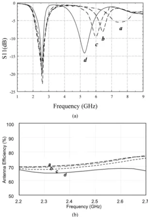
Fig. 3. (a) Simulated return losses, as functions of frequency, for the antennas shown in Fig. 2. (b) Simulated radiation efficiency, as functions of frequency, for the antennas shown in Fig. 2.
inverted-F antennas (as Fig. 2) with the total length of the metal line kept similar and spiraled gradually were designed. The total length of the strip from short point to open end in Fig. 2(a) is 25.5 mm. The fundamental resonant frequency of these an-tennas should remain about the same, which can be verified from the simulated return losses shown in the curves a–d of Fig. 3(a). As a matter of fact, the return losses of the four antennas are all better than 15 dB, except for the variation of the bandwidth.
wavelength is used. (Note that the ground plane is a part of the antenna, on which the induced current contributes to the radi-ation performance of the antenna.) However, the bandwidth of the 2.45 GHz band shown in Fig. 3(a) becomes narrower with the smaller antenna size. This can be attributed to the increasing of antenna quality factor due to the antenna size [22]. The effi-ciency of the well matched spiraled inverted-F antenna around 5.2 GHz is about 50%, which is lower than that (70%) of a typ-ical PIFA designed at the same frequency. In the 5 GHz band, the proposed antenna operates at the high order mode with three quarter wavelength resonance. The current flows in the spiral with different directions, thus reducing the radiation efficiency of the antenna.
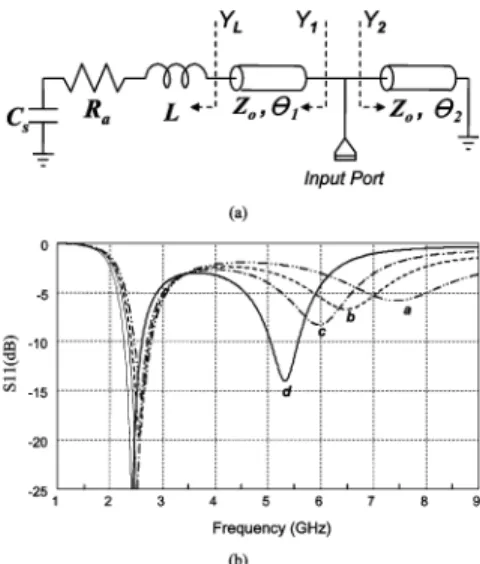
For conceptually understanding the frequency reduction ef-fect of the second resonance, a brief equivalent circuit model for the spiraled PIFA is proposed as shown in Fig. 4(a), where the PIFA is modeled as a short-circuited transmission line of length in shunt with a transmission line of length loaded by an effective radiation resistance . An inductor is inserted in the end of the open-circuited transmission line in order to take account of the spiraling effect of the antenna tail and the para-sitic inductance of the transmission line. In addition, a parapara-sitic capacitor shunt to ground for fringe field is considered in the open-end transmission line. The input admittance is
(1) where and denote the characteristic admittance and phase constant, respectively, of the transmission line. The admittance can be written as
(2) The input reflection coefficient , or the return loss, can thus be calculated from
(3) Fig. 4(b) illustrates the calculated return losses, functions of frequency, for the equivalent circuit model of the spiraled an-tenna. The characteristic impedance is 180 , which is about the EM-simulation value of the characteristic impedance for the
Fig. 4. (a) Equivalent transmission line model for the spiraled PIFA. (b) Sim-ulated return losses of the equivalent model withZ = 180 222 = 57:4 , 222 = 18:3 , C = 0:13 pF, R = 150 and L = 3:7, 6, 8, 12 nH.
antenna’s quasi transmission line portion. The electrical length is set as and at 2.45 GHz. The total electrical length is around quarter wavelength at 2.45 GHz. Con-sider the small parasitic capacitor to be 0.13 pF as fringe field. The effective radiation resistance is around 150 . The inductor is related to the spiraled strip, which is the domi-nant factor of the model. From the intuition, its value should increase as the strip is spiraled more. However, since the induc-tance caused from the spiraling is distributed in the structure, it is hard to extract from the EM simulation. In this study, this in-ductor was chosen as 3.7, 6, 8, and 12 nH for the antennas (a) to (d) in Fig. 2, respectively, so as to fit the EM-simulation results Fig. 3(a) of the antennas.
One can observe from Fig. 4(b) that in the frequency span, two resonances are generated by each circuit. The higher reso-nant frequency at 7.35 GHz moves towards the lower frequen-cies of 6.5, 6, and 5.25 GHz, although, at the same time, the lower resonant frequency is remained around 2.45 GHz. Finally the specified dual-band operation is achieved by only one res-onator. The results resemble those of the spiral antennas quite well, meaning that the equivalent circuit model including the value-changing inductor does explain the frequency character-istics of the proposed dual-band antennas.
The spiral PIFA of Fig. 2(d) [or Fig. 1(a)] was fabricated on an FR4 substrate with thickness 0.8 mm. The ground size of the substrate is set as . The
antenna occupies an area of , which
is only 50% of that of the PIFA without spiraling. The others
parameters are , , and
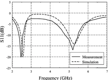
both the width and gap of spiral . Fig. 5 shows the measured return loss corresponding to the EM simulated one. Both results agree each other quite well. The measured 10-dB bandwidth is 140 MHz centered at 2.45 GHz and 756 MHz at 5.25 GHz.
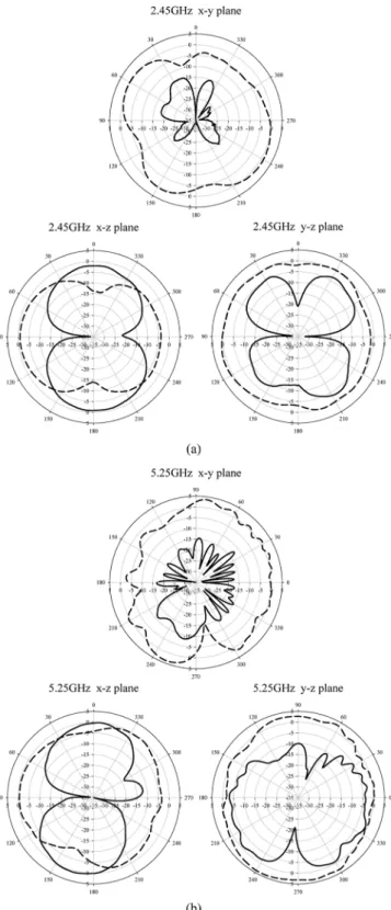
The measurement radiation patterns of the antenna are pre-sented in Fig. 6(a) for 2.45 GHz and Fig. 6(b) for 5.25 GHz. Comparing with the conventional antenna (not shown here), the
Fig. 5. Simulated and measured return losses to frequency of the dual-band spiraled PIFA.
radiation patterns at the lower frequency of the proposed spi-raled antenna are not varied much. The radiation pattern in the plane is omnidirectional with a peak gain of 1.59 dBi and average gain about . The radiation patterns at 5.25 GHz are also omnidirectional in the and planes. The peak gain and average gain are respectively near 3 and in the plane, and are about 0 and in the plane.
III. DUAL-BANDCOUPLINGPIFA
The second PIFA-related antenna introduced in this paper is one with a coupling configuration as illustrated in Fig. 1(b). The size of the conventional PIFA is limited by the large in-verted-L structure. This length can be reduced by cutting part of the inverted-L’s tail and then connecting a shunt capacitor with suitable capacitance. In this section, we use a printed ca-pacitor, instead of a lumped caca-pacitor, to accomplish the goal. Fig. 1(b) depicts the PCB layout of the design. For a start, let the end of the large inverted-L connect to the top of the PCB by a via and bend downwards. Then stretch a small portion of the ground plane on the bottom to make a gap or overlap region with the downwards bending end. This produces an equivalent ca-pacitor with one terminal connected to the end of the inverted-L and the other to the ground. The capacitance can be adjusted by changing the size of the gap or overlap region.
Instead of a direct contact, the feeding microstrip line is connected to the horizontal metal line through a coupling section of length . The structure can also be viewed as two coupled monopole antennas with different orientation. The small inverted-L monopole antenna on the top of the substrate is designed for operation at the higher frequency, whereas the large monopole antenna on the bottom is for the lower frequency. The structure looks like an inverted-E shape. The complete structure shows that the antenna occupies a region of , which is about 50% of a typical
PIFA with the ground size of .
The small inverted-L antenna has a total length about a quarter wavelength of 5.25 GHz while the large one is with a length near a quarter wavelength of 2.45 GHz. In the design, the length of the coupling section is varied so
Fig. 6. Measured radiation patterns at the principal planes for the dual-band spiraled PIFA at (a) 2.45 GHz and (b) 5.25 GHz. (solid line denotes E-theta; dashed line denotes E-phi).
as to get a good matching at both bands. The other lengths ( and ) are changed according to the required resonant lengths. Fig. 7 shows the EM simulation return loss (solid curve) of the designed dual-band antenna ( , , and ). The simulation result (dashed curve) for a small inverted-L antenna alone is also shown for comparison. It is seen
Fig. 7. Simulated return loss of the small inverted-L antenna (dashed line) with l2 = 4:8 mm and h = 4:9 mm. The width of the horizontal strip is 1.27 mm and the width of the vertical strip is 1.46 mm. The parameters arel = 12 mm, h = 4:9 mm, l = 4:8 mm, l = 2:2 mm, l = 1:2 mm, g = 4:2 mm, g = 4:4 mm, g = 1:2 mm, and the strip width of large monopole = 1 mm.
Fig. 8. Current distributions on the coupling PIFA at (a) 2.45 GHz and (b) 5.25 GHz.
that, the coupling PIFA structure does exhibit two wideband res-onances, one at 2.45 GHz and the other at 5.25 GHz. In addi-tion, note that the higher resonant band produced by the small inverted-L antenna has only a little change due to the placement of the large inverted-L.
To demonstrate the operation of this dual-band antenna, Fig. 8 performs the current distribution of each operation band. Fig. 8 shows the excited current distributions on the coupling PIFA at the lower (2.45 GHz) and higher (5.25 GHz) frequen-cies, respectively. At the lower frequency Fig. 8(a), the resonant large inverted-L antenna extracts the current from the small one so that a typical PIFA current pattern is produced over the whole antenna structure. The small inverted-L serves as a feeding structure for the resonant large inverted-L antenna. And the large monopole strip forms a quarter-wavelength resonator.
Fig. 9. Simulated and measured return losses of the miniaturized dual-band coupling PIFA. The parameters arel = 12 mm, h = 4:9 mm, l = 4:8 mm, l = 2:2 mm, l = 1:2 mm, g = 4:2 mm, g = 4:4 mm, g = 1:2 mm, and the strip width of large monopole= 1 mm.
The current flows are in the same direction on the overlapped parts of small inverted-L and large monopole antenna, which enhances the horizontal radiation field. At the higher frequency Fig. 8(b), both the small and large inverted-L monopoles have strong current distribution at 5.2 GHz. As predicted, the small inverted-L monopole does behave as a resonant quarter-wave-length one. The current on this small monopole induces that on the large one with a half-wavelength resonance. It is noticed that the induced current on the large inverted-L monopole is different from that of the second resonant mode of a direct-fed monopole (which is a three quarter wavelength resonance).
The coupled PIFA of Fig. 1(b) was fabricated on a FR4 sub-strate with thickness 0.8 mm. The used ground size is
. The antenna occupies an area of
. The other parameters are ,
, , , ,
, and the strip width of large monopole . Fig. 9 presents the measured return loss (solid curve), as a function of the frequency. The EM simulation result (dashed curve) is also shown for comparison. Both results agree well in the whole frequency range. The measured 10-dB bandwidth around 2.45 GHz is 240 MHz while the bandwidth around 5.25 GHz is 672 MHz. The measurement radiation patterns of the antenna are presented in Fig. 10(a) and (b) for 2.45 and 5.25 GHz, respectively. The total electrical field in and planes are quite omnidirectional for both frequencies. A peak gain of 1.2 dBi and average gain of are obtained with respect to 2.45 GHz in the plane, whereas a peak gain of 3.93 dBi and average gain of 1.16 dBi are gotten at 5.25 GHz. As the gain and pattern are similar with the spiraled inverted-F antenna, the antenna efficiency is also similar.
IV. CONCLUSION
In this paper, two novel PIFA-related dual-band antennas with spiraled and coupled structures have been proposed and demon-strated. Through the features of the conventional PIFA, we have reshaped the original antenna to a spiral structure for the pur-pose of miniaturization and dual-band operation. A dual- band
Fig. 10. Measured radiation patterns at the principal planes for the miniaturized dual-band coupling PIFA at (a) 2.45 GHz and (b) 5.25 GHz. (solid line denotes E-theta; dashed line denotes E-phi).
equivalent circuit model for spiraled antenna has been devel-oped as well in order to examine the effects with the tail of the antenna spiraled little by little. The size of the proposed spiraled antenna is about 50% of a conventional one.
Moreover, we introduced an alternative way for operating at dual frequencies by modifying the PIFA structure into two cou-pling inverted-L’s with different sizes. The smaller one is
re-sponsible for the higher operating frequency, whereas the larger one is for the lower frequency. The simulation current distribu-tions at the two frequencies have been shown for demonstration of the operation principle. The size of the proposed coupling PIFA structure is approximately 50% of a typical one.
Both the proposed PIFA-related miniaturized antennas not only hold most of the properties of the conventional antennas but also provide more options for dual-band antenna designs. The analysis of the antennas shows that the two operating fre-quencies at both 2.45 and 5.25 GHz can easily be tuned and the measured radiation patterns are well-behaved at both fre-quency bands with good antenna gains. Finally, since the band-widths of the higher band for both antennas are about 700 MHz, it is easy, after upwards shifting the center frequency, to cover all signal frequencies (from 5.15 to 5.825 GHz) of the IEEE 802.11a WLAN application.
ACKNOWLEDGMENT
The authors would like to give their deep appreciation to one of the reviewers for the valuable discussion about the antenna efficiency, which makes the improvement of the paper quality.
REFERENCES
[1] C. Wu, “Printed Antenna Structure for Wireless Data Communica-tions,” U.S. 6 008 774, 1999.
[2] C. Soras, M. Karaboikis, G. Tsachtsiris, and V. Makios, “Analysis and design of an inverted-F antenna printed on a PCMCIA card for the 2.4 GHz ISM band,” IEEE Antennas Propag. Mag., vol. 44, pp. 37–44, Feb. 2002.
[3] V. Stoiljkovic and G. Wilson, “A small planar inverted-F antenna with parasitic element for WLAN applications,” in Proc. 10th Int. Conf. on Antennas and Propagation, Apr. 1997, vol. 1, pp. 82–85.
[4] T. Tiehong and Z. Zheng, “Applications of planar inverted-F antenna for bluetooth,” in Proc. Int. Conf. Communication Technology (ICCT 2003), Apr. 2003, vol. 2, pp. 1230–1233.
[5] Y. L. Kuo, Y. T. Cheng, and K. L. Wong, “Printed inverted-F antennas for applications in wireless communication,” in Proc. IEEE AP-S Int. Symp., Jun. 2002, vol. 3, pp. 454–457.
[6] H. Y. D. Yang, “Miniaturized dual-band printed antennas for wireless communications,” in Proc. IEEE AP-S Int. Symp., Jul. 2005, vol. 1A, pp. 450–453.
[7] I. Chen and C. M. Peng, “Microstrip-fed dual-U-shaped printed monopole antenna for dual-band wireless communication applica-tions,” Electron. Lett., vol. 39, pp. 955–956, Jun. 2003.
[8] S. H. Yeh and K. L. Wong, “Dual-band F-shaped monopole antenna for 2.4/5.2 GHz WLAN application,” in Proc. IEEE AP-S Int. Symp., Jun. 2002, vol. 4, pp. 72–75.
[9] J. Y. Jan, L. C. Tseng, W. S. Chen, and Y. T. Cheng, “Printed monopole antennas stacked with a shorted parasitic wire for bluetooth and WLAN applications,” in Proc. IEEE AP-S Int. Symp., Jun. 2004, vol. 3, pp. 2607–2610.
[10] E. S. Angelopoulos, A. I. Kostaridis, and D. I. Kaklamani, “A novel dual-band F-inverted antenna printed on a PCMCIA card,” Microw. Opt. Technol. Lett., vol. 42, pp. 153–156, May 2004.
[11] C. M. Su, K. L. Wong, W. S. Chen, and Y. T. Cheng, “Microstrip-coupled printed inverted-F monopole antenna,” Microw. Opt. Technol. Lett., vol. 43, pp. 470–472, Dec. 2004.
[12] Y.-Y. Wang and S. -J. Chung, “A new dual-band antenna for WLAN applications,” in 2004 IEEE AP-S Int. Symp., Jun. 2004, vol. 3, pp. 2611–2614.
[13] C. Y. Pan, C. H. Huang, and T. S. Horng, “A novel printed monopole antenna with a square conductor-backed parasitic plane for dual-band WLAN applications,” Proc. IEEE AP-S Int. Symp., vol. 1, pp. 261–264, Jun. 2004.
[14] Y. L. Kuo and K. L. Wong, “Printed double-T monopole antenna for 2.4/5.2 GHz dual-band WLAN operations,” IEEE Trans. Antennas Propag., vol. 51, pp. 2187–2192, Sep. 2003.
[15] Y. D. Lin and P. L. Chi, “Tapered bent folded monopole for dual-band wireless local area network (WLAN) systems,” Antennas Wire-less Propag. Lett., vol. 4, pp. 355–357, 2005.
Yu-Shin Wang was born in May 1981 in Taichung,
Taiwan, R.O.C. He received the B.S. degree in communication engineering from the National Chiao Tung University, Hsinchu, Taiwan, R.O.C., in 2003, where he is currently working toward the Ph.D. degree in communication engineering.
He is currently involved with research on mi-crowave circuits, antennas and antenna arrays.
Since 1988, he has been with the Department of Communication Engineering, National Chiao Tung University, Hsinchu, Taiwan, R.O.C., where he is currently a Professor. From September 1995 to August 1996, he was a Visiting Scholar with the Department of Electrical Engineering, Texas A&M University, College Station. He was the leader of a sub-program in the four-year Advanced Technologies for Telecommunications National Research Program, which was sponsored by the Ministry of Education, Taiwan, R.O.C. He has authored or coauthored over 70 technical papers in international journals or conferences, including several invited papers and speeches. His areas of interest include the designs and applications of active and passive planar antennas, communications in intelligent transportation systems (ITSs), LTCC-based RF components and modules, packaging effects of microwave circuits, and numerical techniques in electromagnetic.