國立臺灣大學工學院機械工程研究所 博士論文
Department of Mechanical Engineering College of Engineering
National Taiwan University Ph.D. Thesis
運用磁力與壓電力建構多重擺動風扇冷卻系統 Multiple-vibrating fan cooling system using piezoelectric
force and magnetic force
蘇献欽 Hsien-Chin Su
指導教授:馬小康
Advisor: Hsiao-Kang Ma, Ph.D.
中華民國 101 年 7 月
July 2012
I
ACKNOWLEDGEMENTS
I would like to first thank my advisor Prof. Hsiao-Kang Ma for his guidance, continued advice and support throughout my years in the department. He has always been a great motivator and mentor throughout my stay at NTU. He not only teaches me how to do researches but also teaches me how to be a good man. I would also like to thank the outstanding members at Lab 523 who provided a great working atmosphere and thanks to their help that I will miss a lot. I am also thankful for my family, for their love and support which keeps me going through many years of graduate school.
中文摘要 中文摘要 中文摘要 中文摘要
本研究係針對多重擺動風扇冷卻系統進行效能分析與設計應用,本系統共有 五片風扇,包括一片壓電風扇與一片磁力風扇,在風扇共振效應與磁鐵互斥力的 交互作用下,本系統僅使用一片壓電片便可使五片風扇同時產生擺動,擺動的風 扇會產生強制對流並增強散熱效果。本研究首先進行單片壓電風扇冷卻系統之風 扇在散熱鰭片中的最佳擺放方式與適當運作情況測試,主要對其震動頻率、震幅、
角度、水平位置、垂直位置、消耗功率及兩個無因次數Ri (Gr/RePZT2)與 M 進行
討論,而較難觀察的流場,則以 CFD-RC 進行 3D 模擬來確定風扇擺動時周圍的流 場情形。在決定最佳擺放方式與適當運作情況後,再將此結果運用於多重擺動風 扇冷卻系統之設置。
多重擺動風扇冷卻系統之效能可由風扇震幅與散熱能力討論,因為風扇擺動 時所製造的氣流強度與其震幅有正相關,又本系統共有五片風扇存在,所以可以 利用此五片風扇之震幅總合來估計氣流強度。實驗結果顯示,在消耗功率同為 0.03 W 時,多重擺動風扇冷卻系統的五片風扇,其震幅總合為 32 mm,而單片壓電風 扇冷卻系統之震幅只有 8 mm。本系統亦可與散熱鰭片(finned heat sink)進行結合以 進行散熱效果的測試,本研究使用一 20 W 熱源對一散熱鰭片進行加熱,並以多重 擺動風扇冷卻系統對其進行冷卻,實驗結果顯示,在穩態時,散熱鰭片表面溫度 為 67 ℃,當多重擺動風扇冷卻系統於 36.4 Hz、50 V 狀況運作十分鐘後,散熱鰭 片表面溫度降低至 50 ℃,且消耗功率只有 0.03W。
關鍵字; 壓電風扇、冷卻、強制對流
III
ABSTRACT
This research presents the performance and the applications of a multiple-vibrating fan cooling system composed of one piezoelectric (PZT) fan and four magnetic fans.
The system takes advantage of both the resonant effect and the magnetic repulsive force to make five fans vibrate simultaneously by using one PZT plate. The vibrating fans are able to generate forced convective flow and enhance the cooling ability of the fan cooling system. The work first investigates the optimum arrangement and the suitable operating conditions of a single PZT fan cooling system. The effects of the operating frequency, the fan amplitude, the fan arrangement, the power consumption and the dimensionless PZT-convection number (M and Ri (Gr/RePZT2
) have been analyzed.
Further, a three-dimensional model has been built by using CFD-RC to account for the flow field around a vibrating fan. The results can be applied to a multiple-vibrating fan cooling system.
The performance of a multiple-vibrating fan cooling system can be demonstrated by the fan amplitude and the cooling ability. Because the system is composed of five fans whose amplitudes are each proportional to the generated flow rate, the total amplitude of the fans can be used to estimate the flow rate of the five-fan system. The experimental results show that the total amplitude of the multiple-vibrating fan cooling system is 32 mm at a power consumption of 0.03 W. However, the amplitude of the single PZT fan cooling system is only 8 mm at the same power consumption. The system was embedded into a heat sink heated by a 20 W dummy heater. The temperature of the heat sink surface was maintained at 67 ℃ in a steady state. After turning on the system for 10 minutes under the conditions of 36.4 Hz and 50 V, the heat sink surface dropped from 67 ℃ to 50 ℃ at a power consumption of 0.03 W.
Keywords: Piezoelectric fan, cooling, forced convection.
TABLE OF CONTENTS
ACKNOWLEDGEMENTS ... I 中文摘要 ... II ABSTRACT ... III TABLE OF CONTENTS ... IV LIST OF FIGURES ... VII LIST OF TABLES ... . XI NOMENCLATURES ... XII
CHAPTER 1 INTRODUCTION ... ….1
1.1 Background ... ..1
1.1.1 Piezoelectric material ... 2
1.1.2 Piezoelectric micropump ... 2
1.1.3 Piezoelectric fan ... 3
1.2 Motivation ... 5
1.3 Objective of the present study ... 6
CHAPTER 2 DEVELOPMENT OF VIBRATING FAN SYSTEMS...7
2.1 Characteristics of a piezoelectric fan ... 7
2.1.1 Multilayer piezoelectric plate of a piezoelectric fan ... 7
2.1.2 Power consumption of a piezoelectric fan ... 8
2.1.3 Lifetime of of a piezoelectric fan ... 8
2.1.4 Structure of a piezoelectric fan ... 9
2.2 Design of the multiple-vibrating fan system ... 9
2.2.1 Piezoelectric fan of the multiple-vibrating fan system ... 10
2.2.2 Magnetic fan of the multiple-vibrating fan system ... 10
2.2.3 Structure of the multiple-vibrating fan system ... 10
V
2.3 Force analysis of the multiple-vibrating fan system ... 11
2.3.1 Magnetic forces between the vibrating fans ... 11
2.3.2 Bending force of a magnetic fan ... 12
2.4 Study of the resonant frequency on the multiple-vibrating fan system..13
2.4.1 Resonant frequency of a magnetic fan ... 14
2.4.2 Resonant frequency of a piezoelecric fan ... 17
2.4.3 Resonant frequency of the multiple-vibrating fan system... 18
2.5 Method to modulate the resonant frequency of a vibrating fan ... 19
CHAPTER 3 THEORETICAL MODEL OF A PIEZOELECTRIC FAN COOLING SYSTEM………...22
3.1 Theoretical model for a single piezoelectric fan cooling system ... 22
3.2 Simulation model for a single piezoelectric fan cooling system ... 25
3.3 Theoretical model for a multiple-vibrating fan cooling system ... 27
3.3.1 Direct method for calculating h , ... 27
3.3.2 Approximatiom method for calculating h , ... 28
CHAPTER 4 EXPERIMENTAL DESIGN AND APPARATUS ... 30
4.1 Apparatus for a piezoelectric fan cooling system ... 30
4.1.1 Temperature measurment and record ... 30
4.1.2 Signal generator and amplifier ... 31
4.1.3 Finned heat sink ... 31
4.1.4 High speed camera... 31
4.1.5 Manufacture of a piezoelectric fan ... 31
4.2 Experimental set-up for a single piezoelectric fan cooling system ... 32
4.3 Experimental set-up for a multiple-vibrating fan cooling system ... 32
CHAPTER 5 RESULT AND DISCCUSION ... 34
5.1 Performance of the single piezoelectric fan cooling system ... 34
5.1.1 The arrangement of the system ... 34
5.1.2 The flow field of the system ... 35
5.1.3 The power consumption of the system ... 36
5.1.4 The amplitude of the system ... 36
5.1.5 The correlation between Re and Nu ... 37
5.1.6 The relationship between M and Ri ... 37
5.2 Performance of the multiple-vibrating fan cooling system ... 38
5.2.1 Effect of fan geometries on resonant frequency. ... 38
5.2.2 Effect of the distance between the magnets on resonant frequency ... 38
5.2.3 Performance of the multiple-vibrating fan system ... 39
5.2.4 Cooling ability of the multiple-vibrating fan system ... 40
5.3 Improvement and applicaiton of the multiple-vibrating fan system... 40
5.3.1 Frequency modulation of a magnetic fan ... 41
5.3.2 Double-side magnetic fan ... 41
5.3.3 An application of the multiple-vibrating fan cooling system ...42
CHAPTER 6 CONCLUSIONS ... 43
REFERENCE ... 47
VII
LIST OF FIGURES
Fig.1- 1 A finned heat sink ...51
Fig.1- 2 The combination of a rotary fan and a finned ehat sink ...51
Fig.1- 3 Properties of piezoelectric material ...52
Fig.1- 4 A water circulation cooling system by using a piezoelectric micropump ...52
Fig.1- 5 A piezoelectric fan used for a cooling application. ...53
Fig.1- 6 A piezoelectric actuator used for a cooling applications. ...53
Fig.1- 7 A piezoelectric fan mounted to a constant heat flux surface. ...54
Fig.1- 8 Influences of the dimensions and the material on a vibrating. ...54
Fig.1- 9 A cooling system combines two piezoelectric fans with a heat sink. ...55
Fig.1- 10 A simulation model of a vibrating fin system. ...55
Fig.1- 11 Two vibrating sheets are inserted between the three fins. ...56
Fig.1- 12 Air flow generated by a piezoelectric fan primarily influences on the area of its fan tip. ...56
Fig.1- 13 Air flow generated by a piezoelectric fan is in a small area. ...57
Fig.1- 14 An innovative design of a small finned heat sink (50 mm x 50 mm x 35 mm) with a raked piezoelectric fan ...57
Fig.1- 15 A multiple piezoelectric fans cooling system using three piezoelectric fans58 Fig.1- 16 A multiple piezoelectric fans cooling system using four piezoelectric fans for cooling CPU. ...58
Fig.1- 17 A heat sink with special configuration was used in order to place two piezoelectric fans inside it. ...59
Fig.1- 18 A finned heat sink with nine piezoelectric fans.. ...59
Fig.2- 1 Thickness of a piezoelectric plate can be decreased to maintain the electric field at a lower voltage.. ...60
Fig.2- 2 Power consumption of a piezoelectric plate operated at 60 Hz.. ...60
Fig.2- 3 Power consumption of a piezoelectric plate operated at 60 V.. ...61
Fig.2- 4 Power consumption of piezoelectric plates with different volume at fixed input voltage.. ...61
Fig.2- 5 Schematic view of the piezoelectric fan in this research ...62
Fig.2- 6 Schematic view of a magnetic fan.. ...62
Fig.2- 7 Schematic view of the multiple-vibrating fan system.. ...63
Fig.2- 8 A magnetic fan is fixed on a clamp end that can be moved along the moving direction.. ...63
Fig.2- 9 Repulsive forces between vibrating fans.. ...64
Fig.2- 10 Repulsive force between two cylindrical magnets ...64
Fig.2- 11 Four effective magnetic forces existed in this system ...65
Fig.2- 12 A magnetic fan with its end fixed is bent by a concentrated load applies at a point ...65
Fig.2- 13 Fixed end and non-fixed end cantilever beams ...66
Fig.2- 14 The piezoelectric fan made by Yoo et al ...66
Fig.2- 15 The system with uniform resonant frequency...67
Fig.2- 16 The frequency modulator is added to a magnetic fan ...67
Fig.3- 1 The arrangement of thermocouples in the heat sink ...68
Fig.3- 2 Simulation model of the single piezoelectric fan cooling system ...68
Fig.3- 3 The pressure field of the downstream domain with different thicknesses ....69
Fig.3- 4 The orientations of the magnetic fans are the same ...69
Fig.4- 1 A thermal meter used in this research (Agilent 34970A) ...70
Fig.4- 2 A signal generator (GW Instek SFG-2004 4MHz) ...70
Fig.4- 3 A high Voltage Amplifier (A. A. Lab-Systems A-303) ...71
IX
Fig.4- 4 The geometries of the finned heat sink ...71
Fig.4- 5 Thermocouples are pasted on the center of the rectangular sections ...72
Fig.4- 6 A screenshot from the movie recorded by high-speed mode ...72
Fig.4- 7 Screenshot from the movie recorded by normal mode. ...73
Fig.4- 8 The piezoelectric fan is fixed by two screws ...73
Fig.4- 9 The piezoelectric fan is connected with an adjustable basement ...74
Fig.4- 10 The experimental devices………...74
Fig.4- 11 A schematic view of the multiple-vibrating fan cooling system ...75
Fig.5- 1 The orientations of the single piezoelectric fan cooling system ...75
Fig.5- 2 Temperature drop on the bottom and side fin surfaces ( X /L =0.5, θ=0°, frequency=30 Hz, Amplitude=18 mm) ...76
Fig.5- 3 M versus the horizontal orientation (λ=5 mm, θ=0°, frequency=30 Hz, Amplitude=18 mm) ...76
Fig.5- 4 Flow field near the bottom and the side surfaces (X /L =0.5, λ= 5 mm, θ=0°) ...77
Fig.5- 5 Power consumption of the piezoelectric fan (X /L =0.5, λ= 5 mm, θ=0°, amplitude=10 mm) ...77
Fig.5- 6 Influence of the fan amplitude on M ...78
Fig.5- 7 Correlation between Re and Nu of the cooling system ...78
Fig.5- 8 Relationship between M and Ri (X ⁄L =0.5, λ= 5 mm, θ = 0°) ...79
Fig.5- 9 The amplitude of the magnetic fans (case 1) under different frequencies and a voltage of 50 V ...79
Fig.5- 10 The amplitude of the magnetic fans (case 2) under different frequencies and a voltage of 50 V ...80 Fig.5- 11 The amplitude of the magnetic fans (case 3) under different frequencies
and a voltage of 50 V ...80
Fig.5- 12 The magnetic fan is affected by (a) one magnet, (b) a double magnet ...81
Fig.5- 13 Variation of the resonant frequency is affected by one magnet ...81
Fig.5- 14 Variation of the resonant frequency (case 3) is affected by one magnet and a double magnet ...82
Fig.5- 15 The amplitude of a single PZT fan and the multiple-vibrating fan system (case 4) under different voltages ...82
Fig.5- 16 Power consumption of a single PZT fan and the multiple-vibrating fan system under different voltages (both at resonant frequency) ...83
Fig.5- 17 The thermal couples pasted on the system...83
Fig.5- 18 The average surface temperature at the heat sink base under different values of λ ...84
Fig.5- 19 A magnetic fan with a frequency modulator ...84
Fig.5- 20 The relationship between the graduation of the resonant frequency and the resonant frequency of the magnetic fan ...85
Fig.5- 21 A double-side fan ...85
Fig.5- 22 The screenshot of the vibration of a double-side fan ...86
Fig.5- 23 Two double-side fans are actuated by a piezoelectric fan...86
Fig.5- 24 A rotary fan occupies a lot of space ...87
Fig.5- 25 The schematic view of a plate which can be used to fix different vibrating fans ...87
Fig.5- 26 A multiple-vibrating fan cooling system module ...88
Fig.5- 27 A multiple-vibrating fan cooling system module embedded in a motherboard for cooling CPU ...88
XI
LIST OF TABLES
Table 1 Power consumption of rotary fans ... 89
Table 2 Power consumption of piezoelectric fans ... 89
Table 3 Power consumption of single-layer and multilayer piezoelectric fans ... 90
Table 4 Power consumption of piezoelectric plates with different geometries ... 90
Table 5 Lifetime of the piggyback piezoelectric actuator... 90
Table 6 Geometries of the vibrating fans and magnets used in this research ... 91
Table 7 Resonant frequencies of the piezoelectric fans made by Yoo et al... 91
Table 8 Resonant frequencies of the piezoelectric fans in this research ... 91
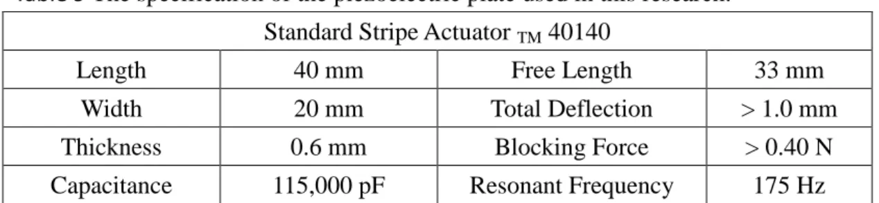
Table 9 The specification of the piezoelectric plate used in this research ... 92
Table 10 The specification of INTEL CPUs. ... 92
NOMENCLATURES
A Surface area of a circular magnet A Total area of the inner fin surface.
A Amplitude of fan
A , Amplitude of fan No.i
A !", Area of each section at the side bottom surface.
A! #", Area of each section at the side fin surface.
a Arm of magnetic force
B% Magnetic flux density
C Constant
D Diameter of magnets
F '(x) Magnetic force between two cylindrical magnets F ',(x) Magnetic force applied to magnet No. i
F()(x) Magnetic force between two cylindrical magnets
*" Resonant frequency of magnetic fan without magnetic damping
*"++ Resonant frequency of magnetic fan with magnetic damping
* Resonant frequency of piezoelectric fan
G Grashof number of the PZT fan cooling system.
g Gravity constant
H Thickness of fan
H Height of the heat sink
h Overall convection heat transfer coefficient
h% Overall convection heat transfer coefficient with natural convection h Overall convection heat transfer coefficient with PZT fan
h , Overall convection heat transfer coefficient with multiple-vibrating fan cooling system
I Area moment inertia of fan
K " Stiffness of a cantilever beam
K"++ Total stiffness of a magnetic fan with magnetic damping K ' The magnetic stiffness induced by two magnets
ΔK ', The magnetic stiffness applied to magnet No. i
k Thermal conductivity of air
L Length of the attached sheet of a PZT fan or length of magnetic fan L0 Characteristic length of the heat sink
L Length of the heat sink
L Characteristic length of the fan
XIII
M Dimensionless PZT-convection number
m Mass of fan
m"++ Effective mass of cantilever beam m 2# Mass of frequency modulator
m 2#,"3 Equivalent mass of the frequency modulator
m ' Mass of magnet
Nu Nusselt number of the PZT fan cooling system.
p Time
Q5 Input heat from the heat source.
Q , 26 7 Total dissipated heat from the fin surface by convection.
Q , Dissipated heat from each section.
Re Reynolds number of a PZT fan cooling system.
R Importance of natural convection relative to the forced convection.
r Radius of magnets
T8! Average temperature of the inner fin surface.
T89, Average temperature of the inner fin surface with piezoelectric fan T89,% Average temperature of the inner fin surface with natural
convection
T89, Average temperature of the inner fin surface. with multiple-vibrating fan cooling system
T: Ambient air temperature.
T !", Temperature of each section at the bottom fin surface.
T! #", Temperature of each section at the side fin surface.
T ; Maximum kinetic energy of frequency modulator while moving
t Thickness of magnet
∆t Time step
V Fan tip velocity
W Width of fan
X() Distance between magnet No. i and magnet No. j X Length of the fan inside the heat sink.
X /L Horizontal orientation.
y?z Deflection depending on the position at z-axis
y?zA Transverse velocity depending on the deflection of the beam
y ; Deflection of beam tip
y ;A Transverse velocity at beam tip
z Moving direction of frequency modulator
Greek symbols μ% Permeability of intervening medium
ρ Density of fan material
σ Poisson ratio of fan material
ω Fan vibrating frequency
β Expansion coefficient
λ Vertical orientation.
θ Inclined angle
ν Viscosity
1
CHAPTER 1 INTRODUCTION
1.1 Background
Thermal management is an important issue today. The increasing power consumption of electronics devices leads to higher heat dissipation. The large content of dissipated heat can lead to high temperatures and heat stresses in the electronic material or device packaging. Further, it is important to maintain the temperature of electronic devices within the normal range. For this purpose, two methods are commonly used. One is natural convection, in which a finned heat sink is used to provide a large surface area for heat dissipation, as shown in Fig.1-1. The other is the combination of a rotary fan and a finned heat sink, as shown in Fig.1-2; the use of a fan increases the convection heat transfer of the heat sink. The fan is also the most common method used for cooling CPUs (Central Processing Units) today. The power consumption of a rotary fan depends on its size. According to Table 1 [1, 2, 3, 4], the power consumption of a rotary fan with a finned heat sink measuring 120 mm x 120 mm in dimensions is usually more than 1.5 W. Even the power consumption of the smallest fan (8 mm x 8 mm) is greater than 0.3 W.
However, power consumption has become an important issue in the twenty-first century. Today, we frequently choose to save energy by reducing the power consumption of electronic devices and machines, in all respects. For example, piezoelectric plates, with the advantages of low power consumption and small sizes, have emerged as the preferred driving devices for cooling systems. The power consumption of piezoelectric devices, as shown in Table 2 [5, 6], is ten times smaller than that of the smallest fan. Further, if cooling devices fabricated from piezoelectric plates can be substituted for rotary fans, this shift should provide an overall significant energy savings.
1.1.1 Piezoelectric material
The first experimental demonstration of the piezoelectric phenomenon was published in the 1880s [7]. The piezoelectric effect describes the relationship between the mechanical stress and the electrical voltage within a piezoelectric material. The piezoelectric effect is a reversible process. The direct piezoelectric effect can be described by the production of an electric charge in a piezoelectric material in response to an applied mechanical stress. The converse piezoelectric effect can be described by the application of an electric charge to cause displacement in the atoms in a material, otherwise known as stress. As shown in Fig.1-3 [8], if a voltage of opposite polarity to that of the poling voltage is applied to a piezoelectric element, the element will become elongated in the direction of the poling voltage. If a voltage of the same polarity as the poling voltage is applied, then the element will become shorter. For applications, an alternating voltage is usually applied. Thus, the element is lengthened and shortened periodically, at the frequency of the applied voltage. The material is able to carry out this periodic movement by consuming very low power.
1.1.2 Piezoelectric micropump
In 2008, Ma et al. presented a piezoelectric liquid cooling device that was named the one-side actuating piezoelectric micropump [9, 10]. The piezoelectric micropump was capable of driving water in a circulation cooling system, as shown in Fig.1-4[9].
The flow rate of the micropump reached 4.1 ml/s at a power consumption less than 0.1 W. The cooling ability of the liquid cooling system was verified by cooling a 30 W dummy heater. According to the experimental results, the circulation system with an open loop was able to maintain the core temperature of the 30-W dummy heater at 37.8 ℃ while the circulation system with the closed loop maintained the core
3
temperature at 54.4 ℃. This result implies that a small piezoelectric plate is capable of driving a liquid cooling system and cooling a heat source at a low power consumption.
1.1.3 Piezoelectric fan
The application of a piezoelectric plate for air flow generation was proposed by Toda and Osaka in the 1980s [11, 12]. Recently, a number of studies on piezoelectric actuators used for cooling applications have been presented, as shown in Fig.1-5 and Fig.1-6 [13, 14], because of the small size, lower power consumption, and long life of the devices [15]. A piezoelectric fan is manufactured by attaching a cantilever beam to a piezoelectric plate. An alternating current is then applied at the resonant frequency of the piezoelectric fan. Thus, the piezoelectric fan is able to operate at a high ratio of fan tip deflection to power consumption [16]. The vibrating cantilever beam can operate with enough air-moving capability as small fans for the cooling of electronic equipment. The theoretical vibration model of a piezoelectric bimorph with a thin elastic plate was derived from a lumped-mass system [17], which indicated that the damping effect in the mechanical wobbling of the attached elastic plate could not be ignored.
Acikalin et al. [18, 19] presented a piezoelectric fan mounted to a constant heat flux surface, as shown in Fig.1-7. Several experimental parameters, including the configuration, the fan amplitude, the fan length, and the frequency, as well as the distance between the fan and the heat source, were explored to assess the cooling ability of the piezoelectric fan. The results demonstrated that the fan frequency and the fan amplitude were the crucial parameters of the design. He also presented an experimentally validated numerical model, which was developed to analyze and predict the flow field and the heat transfer of a piezoelectric fan. The numerical model
agreed with the experimental results to within a 20% deviation [20]. Liu et al.
presented an experimental investigation of the thermal performance of piezoelectric fans. Six piezoelectric fans with various blade geometries were fabricated and tested.
The influence of the geometric parameters, including the horizontal/vertical arrangement and the location of the piezoelectric fan, were examined with respect to the performance of piezoelectric fans [21]. Kimber et al. [22, 23] presented experimental methods of pressure and flow rate measurements for piezoelectric fans.
Further, the Reynolds number was also defined for evaluating the performance of piezoelectric fans. Yoo et al. [24] researched the influences of the dimensions and the material on a vibrating fan, as shown in Fig.1-8. The study indicated that phosphor bronze and aluminum were also appropriate material choices for a vibrating fan. Sheu et al. [25] presented the influence of the bonding glue selection on the vibration of piezoelectric fans. For different glues applied in layers of the same thickness, the vibrational amplitude was found to increase with the Young’s modulus of the glue.
This result implied that the structural damping induced by the glue layer and the bonding method should be strongly considered. Li et al. [26] proposed a rake-shaped piezoelectric fan for small electronics cooling applications. A piezoelectric actuator was coupled to a rake-shaped blade. The blade structure included a base from which many prongs extended. These prongs could be positioned between the fins of a heat sink to break the thermal boundary. In 2010, Petroski et al. [27] proposed a cooling system combined from two piezoelectric fans and a heat sink, as shown in Fig.1-9.
This cooling system had a heat transfer rate five times higher than that of a finned heat sink with natural convection alone. Ma et al. [28] presented a simulation model of a vibrating fin system, as shown in Fig.1-10. These vibrating fins were able to break the thermal boundary layer to enhance the heat transfer rate. A three-dimensional transitional model for the system was successfully built to
5
investigate the major heat dissipation phenomenon. The simulated results demonstrated that the performance of the vibrating fins was strongly affected by the dimensions, the vibrating frequency, the pitch, and the amplitude of the fins. The results also implied that the cooling ability of a heat sink can be increased if vibrating sheets are inserted between the fins, as shown in Fig.1-11.
1.2 Motivation
Although piezoelectric fans are capable of both dissipating heat from a heat source and operating under very low power consumption, it is difficult to implement piezoelectric fans in electronic cooling applications for several reasons. First, piezoelectric fans are only suitable for small power components, because the air flow generated by the fans primarily influences only a small area around the fan tip, as shown in Fig.1-12 [19] and Fig.1-13 [29]. Additionally, piezoelectric fans are usually manufactured on a small scale [5, 6, 16, 18, 21, 24, 30] (less than 75 mm in length and 30 mm in width), which prevents their use in large electronic devices. For example, Fig.1-14 [31] shows an innovative design of a small finned heat sink (measuring 50 mm x 50 mm x 35 mm) with a raked piezoelectric fan. This design demonstrates a method for combining a piezoelectric fan with a finned heat sink. However, this method cannot be applied to a large-finned heat sink because of its small scale.
Second, a piezoelectric plate is sufficient only for a single piezoelectric fan. This means that if a single piezoelectric fan cooling system is intended for expansion into a multiple piezoelectric fan cooling system, more piezoelectric plates will be required, as shown in Fig.1-15. [32]. For example, in Fig.1-16 [33], four piezoelectric fans are applied to the large heat sink to enlarge the flow rate. This construction not only increases the cost of the system but also enlarges its volume. In 2012, Petroski et al.
[27] developed a double piezoelectric fan cooling system to overcome these problems.
As shown in Fig.1-17, two piezoelectric fans are placed inside a heat sink. The system was composed of only two piezoelectric fans while providing a sufficient air flow rate.
Unfortunately, finned heat sinks have already been commonly used in modern applications, so it is impossible to substitute a new style of heat sink for the currently used finned heat sinks in just a few years. This also implies that piezoelectric fans are not suitable for finned heat sink applications because of the many gaps that exist between the fins. For example, Fig.1-18 shows a finned heat sink with nine piezoelectric fans. This design is clearly not economically viable, because the design requires the use of nine piezoelectric plates for completion. Thus, the identification of an efficient method for combining the piezoelectric fans with a finned heat sink is the most important issue.
1.3 Objective of the present study
The objective of the present study is to develop an innovative multiple-vibrating fan system capable of providing a large air flow rate without extra power consumption or cost. Thus, such a system could be used to cool electronic devices at a low cost.
Moreover, the system could be used with a finned heat sink to construct a cooling system without increasing either its volume or the number of piezoelectric plates used.
Hence, the cooling system can be applied to electronic devices both compactly and economically.
7
CHAPTER 2 DEVELOPMENT OF THE VIBRATING-FAN SYSTEMS
2.1 Characteristics of a piezoelectric fan
A piezoelectric fan is usually made of a piezoelectric plate and a mylar sheet.
The characteristics of a piezoelectric fan include low power consumption, a long lifetime and a simple structure. The foundational construction of the piezoelectric plate will be introduced in this section.
2.1.1 Multilayer piezoelectric plate for a piezoelectric fan
The large deformation of a piezoelectric plate depends on the application of a sufficiently high electric field across it. Unfortunately, the application of high voltage is not preferred in small electronic devices, due to cost, safety and heat dissipation issues. However, piezoelectric materials can be stacked to linearly increase the overall deflection while maintaining the low voltage requirement. As shown in Fig.2-1 [34, 35], the thickness of a piezoelectric plate can be decreased to maintain the electric field at a lower voltage. Then, the thin piezoelectric plates can be stacked together to increase the overall deflection. This structure can be further explained by the use of an electric circuit diagram. A single-layer piezoelectric plate can be represented as a series-connected circuit, in which the electric field depends on the thickness of the piezoelectric plate. However, a multi-layer piezoelectric plate can be represented as a parallel-connected circuit; that is, the electric field across each layer can be maintained at a low value while providing large deflection. According to this design, the deflection of a piezoelectric plate can be increased while maintaining a low input voltage. Table 3 [31] shows the performance of two piezoelectric fans with the same geometric configuration and indicates the effectiveness of decreasing the driving voltage.
2.1.2 Power consumption of a piezoelectric fan
The power consumption of a piezoelectric plate depends on its volume, the input frequency and the input voltage. Fig.2-2 shows the power consumption of a piezoelectric plate operated at 60 Hz. The power consumption increases exponentially as the input voltage is increased. The power consumption reaches 0.4 W when the input voltage is increased to 100 V. Fig.2-3 shows the power consumption of a piezoelectric plate operated at 60 V. The power consumption increases approximately linearly as the input frequency is increased. The power consumption reaches 0.1 W when the input frequency is increased to 100 Hz. Fig.2-4 shows the power consumption of piezoelectric plates with different volumes at a fixed input voltage.
The power consumption increases approximately linearly as the volume is increased.
According to Table 4 [6], a 6.4 mm-wide piezoelectric plate consumes approximately twice the power of a 3.2 mm-wide piezoelectric plate. According to the data shown in this section, the approximate power consumption of the piezoelectric plates can be assessed quickly by the input frequency and the volume, because both show a linear dependence. However, the effect of the input voltage on the power consumption should be measured by the use of a device.
2.1.3 Lifetime of a piezoelectric fan
According to a previous study [36], the lifetime of a piezoelectric actuator depends on its driving voltage, the room temperature and the environmental humidity.
S. Nakamura et al. [37, 38] have performed fatigue tests to acquire the fundamental data necessary for predicting the lifetime of a piggyback piezoelectric actuator operated at 3,000 Hz. The piezoelectric actuator studied was 5.4 mm wide, 6.3 mm long and 0.2 mm thick. The lifetime of a piggyback piezoelectric actuator is defined as the number of driving cycles necessary to produce 95% of the initial displacement
9
of the actuator. The result shows that the lifetime of the piggyback piezoelectric actuator under heavy use conditions is more than five years, as shown in Table 5.
However, the operating frequency of a piezoelectric fan is usually less than 100 Hz.
Thus, the piezoelectric fan is expected to have a longer lifetime than a piggyback piezoelectric actuator operated at 3,000 Hz.
2.1.4 Structure of a piezoelectric fan
A piezoelectric fan is manufactured by attaching a piezoelectric plate to a cantilever beam made of either metal or plastic (e.g., PVF2, Mylar). When an alternating voltage is applied, the piezoelectric plate expands and contracts in an alternating form at the same frequency as the applied voltage. This results in the vibration of the cantilever beam, which produces air flow. In this manner, the piezoelectric fan is capable of vibrating very quickly with a high operating frequency.
However, a piezoelectric fan should be operated at its resonant frequency. Thus, the piezoelectric fan can be operated at a high ratio of fan tip deflection to power consumption [15] and efficiently produces an oscillating flow.
Because piezoelectric fans are used for electronic cooling and energy saving applications, the important issues are the quantity of the induced air flow and the power consumption. The operating frequency and the amplitude of a piezoelectric fan have a significant influence on the flow rate and power consumption. Thus, the geometry and the materials should be considered carefully, because they directly affect the resonant frequency. Table 6 shows the different geometries and the materials of the vibrating fans used in this research.
2.2 Design of the multiple-vibrating fan system
The multiple-vibrating fan system takes advantage of the magnetic force and the
piezoelectric force to operate in high performance applications. However, a previously investigated piezoelectric fan does not include the component for taking advantage of the magnetic force. Thus, the vibrating fans used in this research should be designed differently from the previous piezoelectric fan for the application of magnetic force to the system.
2.2.1 Piezoelectric fan of the multiple-vibrating fan system
Fig.2-5 shows a schematic view of the piezoelectric fan used in this research. A cantilever beam made of phosphor copper or plastic is attached to a piezoelectric plate, as in the previous piezoelectric fan. The only difference between this piezoelectric fan and the previous one is the circular magnet incorporated on the fan tip. The magnet can be attached on the tip of the fan either by physical or chemical methods means that the magnetic force can be applied with the direction of motion while the piezoelectric fan is vibrating.
2.2.2 Magnetic fan of the multiple-vibrating fan system
Fig.2-6 shows another vibrating fan used in this work, named the magnetic fan.
The magnetic fan is compeletly made of phosphor copper or plastic. A cylindrical magnet is attached on the tip of the fan such that the magnetic force can be applied to the fan by the magnet while the other magnets also move toward the magnet. This fan has a simple structure and and can be fabricated at a low cost. The geometries of the fans used in each case are shown in Table 6.
2.2.3 Structure of the multiple-vibrating fan system
Fig.2-7 shows a schematic view of the multiple-vibrating fan system. Four
11
magnetic fans (No.2、No.3、No.4、No.5) and one piezoelectric fan (No.1) are used in this system. The pole of a given magnet is opposite that of the adjacent magnets. Thus, all magnetic forces applied to these magnets are repulsive. The resonant frequency of each fan should be adjusted to the same value by varying the geometries of the fans.
Thus, the fans can be operated at the highest ratio of fan tip deflection to power consumption [16]. By this design, the magnetic fans can receive the force applied by the piezoelectric fan through the magnets on their fan tips. Thus, these fans are able to vibrate simultaneously with the vibrating piezoelectric fan in the middle.
2.3 Force analysis of the multiple-vibrating fan system
The interactive magnetic forces in the multiple-vibrating fan system are very complex, hence it is necessary to simplify the forces to more easily analyze the system.
Toward this end, an experimental plate, as shown in Fig.2-8, was used. In the figure, a magnetic fan is fixed on a clamp end that can be moved along the moving direction.
Thus, the vibrating fans can be easily adjusted to the desired position, and the influence of the distance between the magnets on the interactive magnetic forces can be readily investigated.
2.3.1 Magnetic forces between the vibrating fans
Fig.2-9 shows the interactive magnetic forces between the fans. This is a complex system in which the magnetic forces affect one another. The problem is how to simplify the magnetic forces such that the system can be more easily analyzed.
Equation (2.1) expresses the magnetic force between the two cylindrical magnets [39], as shown in Fig.2-10, where B0 is the magnetic flux density, A is the area of the magnets, t is the thickness of the magnet, r is the radius of the magnet, x is the distance between two magnets, and µ0 is the permeability of the intervening medium.
F '?x J KLMNORSPNM?6Q6N NT K;UNV?;QW6U NX?;Q6W NT (2.1)
According to Equation (2.1), the magnetic force depends on the characteristics of the magnets as well as the distance between two magnets. Fig.2-11 shows that FU(W is the magnetic force between magnets No.1 and No.2. Similarly, FU(Y is the interactive force between magnets No.1 and No.3. Thus, the total magnetic force applied to magnet No.1 can be expressed as Equation (2.2),
∆F ',U?x J FW(U?x V FY(U?x V FZ(U?x V F[(U?x (2.2)
Each applied force in Equation (2.2) can be calculated from Equation (2.1). The only unknown parameter is the distance between the two magnets. In this study, the distance between two adjacent magnets is set at a constant value. When the distance is set at 10 mm, XY(U is twice the value of XW(U. The ratio of FW(U to FY(U is calculated as 11.43, so the magnetic force, FY(U, can be eliminated. The condition is the same for F[(U. Thus, Equation (2.2) can be simplified to Equation (2.3).
∆F ',U?x J FW(U?x V FZ(U?x (2.3)
By means of this elimination, the magnetic force applied to No.3 can be simplified to Equation (2.4), as follows:
∆F ',Y?x J FY(W?x (2.4)
13
After this procedure, there are only four effective magnetic forces in existence in this system. Thus, the complex system can be simplified as shown in Fig.2-11.
2.3.2 Bending force of a magnetic fan
Because the magnetic fan is bent by the repulsive magnetic force, it can be seen as a fixed-end beam in which a concentrated load can be applied at any point, as shown in Fig.2-12. The relationship between the maximum deflection (A ) and the repulsive force (F ') can be expressed as Equation (2.5) [40].
A J \]^_` N?3L X a (2.5)
In this equation, F ' is the force applied to the fan, L is the length of the magnetic fan, I is the area moment inertia of the fan, E is the Young’s modulus of the fan, A is the amplitude of the fan and a is the arm of the repulsive force. By substituting I J 1 12⁄ WHY and a J 0.93L into Equation (2.5), it can be simplified to Equation (2.6).
A J 3.58 `n5\]^lmm (2.6)
From this equation, it can be understood that the thickness and the length of the magnetic fan are the main factors that influence its deflection.
2.4 Study of the resonant frequency on the multiple-vibrating fan system
Generally, the best operating frequency of a vibrating fan is its resonant frequency. This condition minimizes the power consumption of a vibrating fan while
providing the maximum amplitude [16]. The multiple-vibrating fan system takes advantage of the resonant frequency to improve the performance of the system. The key aspect of this approach is that the fans must be precisely manufactured to ensure that their resonant frequencies are the same. In this manner, each fan is able to operate in its best performance.
2.4.1 Resonant frequency of a magnetic fan
The resonant frequency of the magnetic fan depends on the length, the thickness, the width and the end mass of the fan, as well as the repulsive force produced by the magnet on its tip. The motion of the magnetic fan can be represented as that of an end-loaded cantilever beam and its stiffness can be expressed by Equation (2.7) [41].
K " J `n5Y.[olmm (2.7)
In this equation, W is the width, H is the thickness, and L is the length of the fan. The
effective mass of the cantilever beam can be approximated as m"++. For the magnetic fans, the effective mass is equal to m 'V 0.24m [41], where m is the mass of the fan and m ' is the mass of the magnet added on the tip of the fan. Thus, the resonant frequency of the magnetic fan, without considering the magnetic force, can be expressed as Equation (2.8).
*" J WRU q \]^rst]\Q%.WZ s (2.8)
However, the magnetic force introduces an additional stiffness within the system.
Thus, this further effect on the resonant frequency of the magnetic fan should be
15
considered. Cylindrical magnets are used to apply a magnetic force to the magnetic fans. The magnetic force between two specific cylindrical magnets is given as Equation (2.9) [39].
F()?x J KLMNORSPNM?6Q6N NT u;U
vwxNVy; U
vwxQW6zNXy; W
vwxQ6zN{ (2.9)
During the vibration of the fans, the effect of the repulsive magnetic force can be represented as that of a spring in compression. This force induces an additional stiffness that influences the resonant frequency of each fan. The stiffness, K '?x , can be given as a function of the distance between the magnets, as shown in Equation (2.10).
K '?x J |##;\]^| (2.10)
By inserting Equation (2.1) into Equation (2.10), K '?x can be expressed as Equation (2.11).
K '?x J KLMNORSPNM?6Q6N NT }X;WmX?;QW6W mV?;Q6Z m~ (2.11)
According to Fig.2-11, the magnetic force applied to the No.2 fan can be expressed as Equation (2.12).
∆F ',W?x J FW(U?x V FW(Y?x) (2.12)
Thus, the additional magnetic stiffness applied to fan No.2 can be expressed as
Equation (2.13).
∆K ',W?x J |KLMNORSPNM?•Q€6N NT K•X;Nw‚mW X?;Nw‚WQW6mV?;Nw‚ZQ6mƒ X
•X;NwmmW X?;NwmWQW6mV?;NwmZQ6 mƒT| (2.13)
However, the additional stiffness applied to fans No.3 and No.5 is different from that of fans No.2 and No.4, because they are each affected by only one magnet. Thus, the additional stiffness of No.3 can be expressed as Equation (2.14).
∆K ',Y?x J |KLMNORSPNM?6Q6N NT •X; W
NwmmX?; W
NwmQW6mV?; Z
NwmQ6 mƒ|(2.14)
The additional stiffness induced by the magnetic force is positive for the repulsive force and negative for the attractive force. However, all interactive magnetic forces in this system are repulsive forces such that the magnetic forces always contribute a positive stiffness to the total stiffness. With the added effect of the magnetic stiffness, the total stiffness of the fan can be expressed as Equation (2.15).
K"++ J K " V ΔK ' (2.15)
Thus, the resonant frequency is a function of the beam stiffness and the additional stiffness. The resonant frequency can be expressed as Equation (2.16).
*"++ JW„U q \]^…Q%.WZt†† s (2.16)
17
2.4.2 Resonant frequency of a piezoelectric fan
A piezoelectric fan is manufactured by bonding a piezoelectric plate to a cantilever beam, which is made of metal or plastic; hence, the characteristics of the cantilever beam and the characteristics of the piezoelectric plate both influence its resonant frequency. Thus, the method for calculating the resonant frequency becomes very complex. It was found that the resonant frequency of a vibrating plate is primarily affected by its length, as shown in Equation (2.17) [42].
*€ ∝l5NqUWˆ?U(‰` N (2.17)
Where ρ, σ, E, L and H are the density, the Poisson’s ratio, the Young’s modulus, the length and the thickness of the cantilever beam, respectively. However, this formula is for an ideal cantilever beam with a perfectly fixed end. It cannot be used to calculate the resonant frequency of the piezoelectric fan directly because its end is not perfectly fixed, as shown in Fig.2-13. Instead, Yoo et al. [24] proposed Equation (2.18) to calculate the theoretical resonant frequency of a piezoelectric fan.
*€ J Gl5NqUWˆ?U(‰` N (2.18)
This equation is only concerned with the characteristics of the cantilever beam. The effects of the bonding glue and the characteristics of the piezoelectric plate are attributed to the factor G. In this equation, G and *€ are unknown numbers and the other numbers are constants. Although the factor G is a variable for many reasons, it can be calculated experimentally. Table 7 [24] shows the experimentally measured resonant frequencies of the fans, as shown in Fig.2-14, and the corresponding values
calculated by using Equation (2.18) with the factor G = 0.558. The results show the precision of this equation.
Table 8 shows the measured values from this experimental work. The factor G was calculated for a piezoelectric fan measuring 50 mm in length (basement). It was found that the error in the factor G was less than 6% when L is between 60 mm and 40 mm. However, the error was increased to 27.11% for the fan measuring 25 mm in length. The situation is the same when other fans are used, such as a plastic fan. This result implies that the equation can only be used to assess the resonant frequency of a piezoelectric fan with small variations in length.
2.4.3 Resonant frequency of the multiple-vibrating fan system
Because the system operates in a high performance mode by taking advantage of the resonance effect, each fan in this system should be actuated at its resonant frequency. However, there is only one piezoelectric plate used in this system, which means that the operating frequency of the system is a single number. Thus, the fans in this system should be precisely manufactured to ensure that their resonant frequencies are the same. Fig.2-15 shows both systems with uniform resonant frequency and non- uniform resonant frequency. The system with uniform resonant frequency is an ideal model. Each fan operates at its resonant frequency, 36.7 Hz. Thus, the system can operate at its optimal performance. However, the system with non-uniform resonant frequency is the normal condition, because the resonant frequencies of each fan are affected by the magnetic force, which adds additional stiffness. This non-uniform resonant frequency condition results in a reduced performance, because the fans cannot vibrate at their individual resonant frequencies. Although the issue reduces the performance of the system, the overall performance is still much better than that of a single piezoelectric fan.
19
2.5 Method to modulate the resonant frequency of vibrating fans
According to Equation (2.19), six parameters influence the resonant frequency of a beam.
*" ∝ W„U qlm? \]^`n5Q%.WZm s (2.19)
However, it is inconvenient to change the geometry and the material of the fans to adjust E, W, H, L and m . Additionally, it is impossible to change the magnets (m ') during an experiment. To optimize the performance of the system, a frequency modulator was used. The frequency modulator is the key component for optimizing the performance of the system. This component is used to easily adjust the resonant frequency of a piezoelectric fan or a magnetic fan. A frequency modulator was added to the fan as shown in Fig.2-16. The frequency modulator is a movable mass, and the effective mass can be calculated by the Rayleigh Method.
The maximum kinetic energy of the frequency modulator shown in Fig.2-16 is given by Equation (2.20), where y?zA is the transverse velocity and depends on the deflection of the beam, and where m 2# is the mass of the frequency modulator.
T ;J UWm 2#Šy?zA ‹W (2.20)
The force deflection formula for this beam can be expressed as Equation (2.21).
y?z J \]^_`ŒN?3a X z (2.21)
By substituting y ; into Equation (2.21), y(z) can be demonstrated as Equation (2.22).
y?z J y ; NN?Y (?Yl( (2.22)
Where y ;J \]^_` N?3L X a is the deflection of the fan tip. A similar relationship can be written for velocity and is given as Equation (2.23).
y?xA =y ;A ŒNN?Y (Œ?Yl( (2.23)
By substituting Equation (2.23) into Equation (2.20), the maximum kinetic energy of the frequency modulator can be demonstrated as Equation (2.24).
T ;J UWm 2#?ŒNN?Yl( ?Y (Œ Wy A ;W (2.24)
Thus, the equivalent mass of the frequency modulator at the fan tip is then given by Equation (2.25).
m 2#,"3 J m 2#?ŒNN?Yl( ?Y (Œ W (2.25)
This can be attributed to the effective mass of the fan as shown in Equation (2.26).
*" ∝ WRU •lm??ŽN `n5m
]N?m]wŽ
?m•w] N \•‘Q \]^Q%.WZ s (2.26)
21
By substituting a = 0.93L into Equation (2.26), then Equation (2.26) can be simplified to Equation (2.27).
*" ∝ WRU •lm??ŽN?N.’•wŽ‚.’•m N \•‘`n5mQ \]^Q%.WZ s
(2.27)
By moving the frequency modulator, the resonant frequency of the fan can be adjusted to the value desired.
CHAPTER 3 THEORETICAL MODEL OF A PIEZOELECTRIC FAN COOLING SYSTEM
In this chapter, the thermal analysis method for a piezoelectric fan and the multiple-vibrating fan cooling system will be introduced. Additionally, a simulation model used for calculating the flow field will be presented.
3.1 Theoretical model for a single piezoelectric fan cooling system
First, a method for analyzing the convective heat transfer ability of a single piezoelectric fan will be presented in this section, because the cooling ability of the multiple-vibrating fan cooling system can be inferred from that of a single piezoelectric fan. To calculate the overall convection heat transfer coefficient, the surface of a finned heat sink was divided into fifteen equal sections. The thermocouples were arranged in each section as shown in Fig.3-1. Equation (3.1) shows the energy balance of the heat sink, in which Q5 is the input heat from the heat source, Q , 26 7 is the total heat dissipated from the fin surfaces by convection, and Q , is the heat dissipated from each section.
Q5J Q , 26 7J ∑ QU[”U , (3.1)
Equation (3.1) can be taken as the following Equation (3.2) by substituting the
notations.
Q , 26 7 J h • A • ?T8 X T9 : (3.2)
The total area of the inner fin surface is denoted as A ; T8 is the average !
temperature of the inner fin surface; T: is the ambient air temperature; and h is the
23
overall convection heat transfer coefficient. Thus, the overall convection heat transfer coefficient can be computed by using Equation (3.3).
h J O—˜™–—˜™,š•›]œ? •( ž (3.3)
By dividing the bottom and the side fin surface into five equal sections, as shown in Fig.3-1, the central temperature of a section can be assumed to be the average temperature of the section. Thus, the average temperature of the inner surface can be derived by using the weighting method, as shown in Equation (3.4),
T8 =! ∑¡v¢‚ s]Ÿt,v∗Os]Ÿt,vQW∗∑¡v¢‚ Ÿv‘t,v∗OŸv‘t,v
O—˜™ (3.4)
where T !", is the temperature measured by the thermocouples of each section at the bottom fin surface, and T! #", is the temperature measured by the thermocouples of each section at the side fin surface. Additionally, A !", is the area of each section at the bottom fin surface, and A! #", is the area of each section at the side fin surface.
According to Equation (3.3), the overall convection heat transfer coefficient of the heat sink with the vibrating piezoelectric fan can be calculated from Equation (3.5), and the overall heat convection coefficient of the heat sink with natural convection can be calculated as Equation (3.6).
h JO –—˜™,š•›]œ
—˜™?8•,£¤š( ž (3.5)
h% J O—˜™–—˜™,š•›]œ?8•,M( ž (3.6)
To demonstrate the improvement in the convection ability by using the piezoelectric fan, the dimensionless PZT-convection number ?M is defined as shown in Equation (3.7) to assess the total convection ability.
M J¥8£¤š¥8M J 2 0"# 02¦§"06 2¦ 02"++ 0 "¦6 ¨ 6¥ 6¥" + ¦
6 7 02¦§"06 2¦ 02"++ 0 "¦6 (3.7)
The Reynolds number and the Nusselt number are also calculated to estimate the convective ability of the cooling system. In this study, the fan amplitude is used to determine the length scale. The velocity terms of the Reynolds number and the Nusselt number are based on the maximum fan tip velocity. Thus, the Reynolds number and the Nusselt number can be expressed as Equation (3.8) and Equation (3.9) [43], respectively, as follows:
Re J©O\ªl£¤š (3.8)
Nu J¥8£¤š…l£¤š (3.9)
where ν is dynamic viscosity of air, A is fan amplitude, ω is fan vibrating frequency, k is thermal conductivity of air, and L is the characteristic length of the fan. The characteristic length is chosen by employing the hydraulic diameter of the vibrating fan envelope, as shown in Equation (3.10) [44],
L JW?OZO\n
\Qn (3.10)
25
where W is the width of the piezoelectric fan. Additionally, the cooling effect of this cooling system is a combination of the natural convection and the forced convection.
The importance of the natural convection relative to the forced convection (Ri is defined as Equation (3.11) by the Grashof number and the Reynolds number [45].
Ri J®"-
£¤šN (3.11)
By replacing the notations of Gr and Re , Ri can be expressed as
Ri J'¯y8•,£¤š±Nl£¤š( Nžzl°m (3.12)
In Equation (3.12), the characteristic length (L0) is defined as the height of the fin (H ) for buoyancy effect, and β is the expansion coefficient. For an ideal gas, the thermal expansion coefficient β is expressed as 1/T, where T is assumed to be 273 K.
Therefore, Ri can be rewritten as Equation (3.13).
Ri J'¯5©—˜™NOmy8•,£¤š( žz
\Nl£¤šN (3.13)
3.2 Simulation model for a single piezoelectric fan cooling system
Using CFD-GEOM and CFD-ACE+, a three-dimensional, transitional model was built to account for the flow field of a piezoelectric fan cooling system, as shown in Fig.3-2. To simplify the model, the vibrating motion of the piezoelectric fan was defined by an equation possessing a sine wave, expressed as Equation (3.14), in which ω is the vibrating frequency and L is the length of the piezoelectric fan.

![Table 10 demonstrates the specifications of the INTEL Pentium 4 [46] and the INTEL i7 series](https://thumb-ap.123doks.com/thumbv2/9libinfo/9600955.628939/57.892.334.560.517.740/table-demonstrates-specifications-intel-pentium-intel-i-series.webp)


![Table 1 Power consumption of rotary fans[1, 2, 3, 4].](https://thumb-ap.123doks.com/thumbv2/9libinfo/9600955.628939/104.892.128.751.129.764/table-power-consumption-rotary-fans.webp)
![Table 3 Power consumption of single-layer and multilayer piezoelectric fans[31].](https://thumb-ap.123doks.com/thumbv2/9libinfo/9600955.628939/105.892.144.712.142.341/table-power-consumption-single-layer-multilayer-piezoelectric-fans.webp)
![Table 7 Resonant frequencies of the piezoelectric fans made by Yoo et al[24].](https://thumb-ap.123doks.com/thumbv2/9libinfo/9600955.628939/106.892.126.777.345.962/table-resonant-frequencies-piezoelectric-fans-yoo-et-al.webp)