A bstrAct
Network Function Virtualization (NFV) allows datacenters to consolidate network appliance functions onto commodity servers and devices.
Currently telecommunication carriers are re-ar- chitecting their central offices as NFV datacen- ters that, along with SDN, help network service providers to speed deployment and reduce cost.
However, it is still unclear how a carrier network shall organize its NFV datacenter resources into a coherent service architecture to support global network functional demands. This work proposes a hierarchical NFV/SDN-integrated architecture in which datacenters are organized into a multi-tree overlay network to collaboratively process user traffic flows. The proposed architecture steers traf- fic to a nearby datacenter to optimize user-per- ceived service response time. Our experimental results reveal that the 3-tier architecture is favored over others as it strikes a good balance between centralized processing and edge computing, and the resource allocation should be decided based on traffic’s source-destination attributes. Our results indicate that when most traffic flows within the same edge datacenter, the strategy whereby resources are concentrated at the carrier’s bot- tom-tier datacenters is preferred, but when most traffic flows across a carrier network or across different carrier networks, a uniform distribution over the datacenters or over the tiers, respective- ly, stands out from others.
I ntroductIon
As innovation of network technology accelerates, hardware-based network appliances rapidly reach end-of-life, becoming a primary source of expen- ditures of today’s carrier networks. Currently tele- communication carriers address this problem by adopting Network Function Virtualization (NFV) technology to re-architect their central offices as NFV datacenters [1]. Such NFV datacenters consolidate network appliance functions onto commodity servers and devices, which helps ser- vice providers to speed service deployment and reduce cost. NFV datacenters can be directed by programmable control planes with the Software Defined Networking (SDN) protocol to intelligent- ly steer user traffic flows to the best suited net- work function unit therein.
At present it is still unclear how a carrier net- work shall organize its NFV datacenters into a coherent service architecture and how to deploy the datacenter resources to support global net-
work functional demands. From one perspective, traditional system architects would like to squeeze as many resources into as few super datacenters as possible to achieve economy of scale. From another perspective, telecommunication carriers, when acting as service providers, may want to place sufficient datacenter resources at the Inter- net’s edge to improve user-perceived service response time [2]. This calls for a new NFV ser- vice architecture that can flexibly and efficiently support global network functional demands while accommodating a variety of user traffic patterns and timing constraints.
In response to these challenges, our design philosophy is to divide resources of carrier net- works among many NFV datacenters and con- nect them into a multi-tree overlay network. In the proposed architecture, most of the NFV datacen- ters act as edge datacenters, which are deployed at major subscriber access networks to reduce data transport latency and cross-network traffic.
The remaining NFV datacenters are placed above the edge datacenters in the hierarchy to absorb transient traffic bursts. These NFV datacenters collaboratively process global network functional demands on the carrier networks and intelligently steer traffic flows to a nearby datacenter which yields the minimum expected user-perceived response time. This article introduces our efforts to design such an NFV network architecture and integrate hierarchical NFV datacenters with SDN- based control plane mechanisms.
b Ackground
Traditionally, launching a new network function in a carrier network often requires integrating custom hardware appliances into the existing network infrastructure. Such hardware integra- tion becomes increasingly difficult and expensive as the network size and the number of offered network functions scale up. Furthermore, accel- eration in network technology is shortening hard- ware lifecycles, so custom network appliances now become a significant source of capital and operating expenditures of today’s carrier network.
To address this problem, telecommunication carriers are re-architecting their hardware infra- structure, aiming to offer network functions in a manner similar to the cloud computing paradigm.
It is expected that a future carrier network will be mainly composed of datacenters equipped with NFV-enabled servers. Custom network appliances will gradually be replaced by their software-based counterparts running in NFV datacenters.
Hierarchical CORD for NFV Datacenters: Resource Allocation with Cost-Latency Tradeoff
Ying-Dar Lin, Chih-Chiang Wang, Chien-Ying Huang, and Yuan-Cheng Lai
ACCEPTED FROM OPEN CALL
Digital Object Identifier:
10.1109/MNET.2017.1700037
Ying-Dar Lin and Chien-Ying Huang are with National Chiao Tung University; Yuan-Cheng Lai is with National Taiwan University of Science and Technology;
Chih-Chiang Wang (corresponding author) is with National Kaohsiung University of Science and Technology.
nFV/sdn-I
ntegrAtedA
rchItectureThe European Telecommunications Standards Institute (ETSI) has formally defined an NFV ref- erence architecture [3] with standardized imple- mentations and interfaces with other network components. This standardized NFV architecture enables a carrier network to offer software-im- plemented network functions through commod- ity equipment and devices, thus optimizing the carrier’s hardware infrastructure. However, the conventional tightly-coupled routing paradigm still prevents the carrier network from intelligently steering traffic flows to fully utilize the benefits of NFV architecture [4].
SDN is widely regarded as an ideal complement to NFV architecture because its design decouples the network’s control planes from the data planes.
With SDN, a network’s control plane is directly programmable on a centralized controller. This SDN controller is responsible for dynamically deter- mining the paths of traffic flows across the network and remotely controlling the network’s data planes.
With the support of NFV/SDN-integrated archi- tecture, a carrier network can flexibly deploy its network functions across geographically dispersed NFV datacenters and dynamically steer traffic flows to the best suited network function unit therein [5].
OpenFlow is currently the most popular SDN stan- dard which specifies the communications between the SDN controller and the managed network equipment and devices.
d
AtAcentern
etworkA
rchItecturesExisting datacenter network architectures can be divided into three categories: non-NFV, NFV-only, and NFV/SDN-integrated. In Table 1 we compare our proposal with some well known representa- tives in five areas: economy of scale, agility, expen- ditures, network latency, and SDN-oriented collaboration, to see which of them is most suited for global network function deployment. By agil- ity, we compare their ability of rapidly deploying and scaling new network functions. By network latency, we compare the overall network latency from tenants or subscribers to their designated datacenter. By SDN-oriented collaboration, we examine whether or not they allow multiple data- centers to collaboratively process traffic under SDN control. The meanings of the other aspects are straightforward as their names suggest.
Two well known representatives of the non- NFV category are super datacenter and content delivery network (CDN) architectures. A big IT company such as Google or Amazon typically concentrates hardware resources in a few super datacenters to achieve economy of scale, but the resultant network latency is usually very high due to the centralizing nature. In comparison, a CDN is a collection of autonomous datacenters linked by the Internet to facilitate delivery of Web con- tent and streaming media; the mapping of user requests to CDN servers is performed by a simple Domain-Name-System redirection process [2].
Our proposal and CDN architecture especially focus on leveraging the design concept of edge datacenters and can achieve low network laten- cy. CDN architecture, however, lacks the advan- tage of economy of scale because it partitions its resources among many autonomous datacenters.
Existing super datacenter and CDN architectures still rely on custom network appliances and hence have poor agility and high capital and operating expenditures.
VL2 and NetLord [7] are two representatives of NFV-enabled datacenter network architectures.
VL2 relies on complex end-system address resolu- tion to map service instances to anywhere in the network, without changing the actual network architecture or control plane. With VL2, sending a packet always incurs a directory system look- up for the actual location of the destination.
NetLord uses multiple virtual local area networks to provide high end-to-end bandwidth for mul- tiple tenant networks. The NetLord architecture provides good scalability and logical isolation between tenants. Both VL2 and NetLord have good agility and benefit from economy of scale, but their mapping mechanisms are very complex and cannot guarantee low network latency and low cross-network traffic.
CORD [1] and CloudNaaS [8] are SDN-based network architectures that rely on an OpenFlow controller to remotely maneuver traffic flows in OpenFlow switches. Our proposal also follows this approach. Because all of them adopt NFV/
SDN-integrated architecture, their performance excels in the aspects of agility and expenditures.
Among the three, CORD lacks a service-orient- ed inter-datacenter network and hence performs poorly in the area of economy of scale; Cloud- NaaS cannot guarantee to minimize cross-net- work traffic and network latency because of its complex service mapping mechanism. In com- parison, our proposal allows the managed NFV datacenters to collaboratively process network traffic under an SDN-controlled hierarchical over- lay architecture, thus achieving excellent econo- my of scale, low expenditures, and low network latency at the same time.
h IerArchIcAl nFV/sdn-I ntegrAted d AtAcenter n etwork
In this section, we first introduce the NFV/SDN-in- tegrated datacenter model and then present the proposed hierarchical datacenter network archi- tecture. Finally, we describe the traffic redirection mechanism used by the proposed architecture to optimize the user-perceived service response time.
TABLE 1. Comparison of the existing datacenter network architectures.
Approaches Economy
of scale Agility Expenditures Network latency
Non-NFV Super datacenter Excellent Poor High High
CDN [2] Poor Poor High Low
NFV-only VL2 [6] Good Good Low Uncertain
NetLord [7] Good Good Low Uncertain
NFV/SDN-integrated CORD [1] Poor Excellent Low Low
CloudNaaS [8] Excellent Excellent Low Uncertain
nFV/sdn-I
ntegrAtedd
AtAcenterM
odel For flexible and efficient NFV datacenter control, we integrate a management plane, an SDN con- troller, and an NFV cloud system into a coherent NFV/SDN-integrated datacenter model, as illus- trated in Fig. 1. The management plane contains a resource manager and an information server.The former allocates NFV cloud resources to the admitted traffic flows based on their demands, while the latter monitors the status of the local datacenter and exchanges information with other information servers in the same carrier network.
The SDN controller consists of two modules: a cloud controller and a network controller. The former controls the traffic flows’ service chaining arrangement in the NFV cloud, while the latter controls redirection of the arriving traffic flows.
Every datacenter by default has one deep pack- et inspection (DPI) function running in the NFV cloud to analyze the packets arriving at the data- center. The arriving traffic flows may be redirected to another datacenter to receive the NFV service if doing so improves the user-perceived service response time. Otherwise, the traffic flows will be admitted and switched to the internal network function units according to the NFV service chain- ing arrangement. The network topology module describes the physical arrangement of communi- cation links, OpenFlow switches and routers in the local datacenter. The NFV cloud module includes physical servers, storage and network resources that are used to run network function units.
h
IerArchIcAld
AtAcenterA
rchItecture Our design philosophy is to divide resources of a carrier network among many NFV/SDN-inte- grated datacenters. As illustrated in Fig. 1, a set of the carrier’s datacenters are connected into a multi-tier tree network to collaboratively process traffic from the tenants. The roots of the differ- ent trees are connected via the Internet such that traffic can be routed from one carrier network to another. As mentioned previously, the Tier-1 (leaf) nodes are deployed at the entry points of tenants’ subscriber access networks to reduce data transport latency and cross-network traffic.The remaining datacenters are placed above the leaves in the hierarchy to absorb transient traf-
fic bursts. Every node in a tree, except the root, has a single parent and may have one or multi- ple children. Traffic from a subscriber network is first directed to the local Tier-1 datacenter. Each datacenter either admits and processes the arriv- ing traffic itself or redirects the traffic to another datacenter in the carrier network to optimize the user-perceived service response time. Traffic flows that have already been served by datacenters are routed or switched across the datacenter network architecture to their destinations.
A traffic flow’s source and destination IP addresses decide from which Tier-1 nodes the flow enters and exits the hierarchical datacen- ter architecture. Such IP address information also decides how a flow is routed or switched through the carrier networks. Specifically, the proposed architecture routes/switches three possible types of traffic patterns: namely, same-Tier1-datacenter-and-same-carrier (S&S), dif- ferent-Tier1-datacenter-and-same-carrier (D&S), and different-Tier1-datacenter-and-different-carrier (D&D), in the following way. In the S&S scenario, traffic enters and exits the hierarchical architec- ture from the same Tier-1 datacenter, say DC1,1 in Fig. 1. In this case, the traffic will be redirected from DC1,1 along the tree network to the one, among DC1,1 and its ancestors, which yields the minimum expected service response time.
Once providing the requested NFV services, the chosen datacenter will switch the traffic, along the tree network, back to DC1,1 and then to the destination subscriber network. In the D&S scenario, traffic enters and exits the hierarchical architecture from two different datacenters, say DC1,1 and DC1,2, owned by the same carrier. In this case, DC1,1 will find among DC1,1 and DC1,2 and their ancestors the one that yields the mini- mum expected service response time. The traffic is first redirected to the chosen one to receive the requested NFV services, then switched to DC1,2 and then to the destination. In the D&D scenario, traffic enters and exits from two different datacen- ters, say DC1,1 and DC1,4, owned by two different carriers. In this case, the traffic is first redirected to the one, among DC1,1 and its ancestors, that yields the minimum expected service response time. Once receiving the requested NFV service, the traffic is switched to the root of DC1,1, then FIGURE 1. Model of NFV/SDN-integrated Hierarchical datacenter architecture.
S&S S&D D&D
Information server Resource manager Management
plane
Network topology Information exchange
Traffic
redirection Data
collection Service chaining control Subscriber
manager Resource allocation SDN Network controller Cloud controller
NFV cloud Traffic flows
Internet
...
Tier n
Tier 2
Tier 1
DCn,2 DCn,1
DC2,1 DC2,2 DC2,3
DC1,3 DC1,2
DC1,1 DC1,4
Subscriber network 2 Subscriber
network 1 Subscriber
network 3 Subscriber
network 4
routed via the Internet to the root of DC1,4, and finally switched along the tree network to DC1,4 and then to the destination subscriber network.
As the traffic’s source-destination attributes affect the workload distribution over the datacen- ters, the carriers may adapt their resource alloca- tion strategy to different traffic patterns as well.
In this work we studied four possible types of resource, namely Avg.-dc, Avg.-tier, Heavy-feet and Heavy-head, to test how they improve the user-per- ceived service response time under the effects of different traffic patterns. By Avg.-dc and Avg.-tier strategies, resources are uniformly distributed to all the datacenters and all the tiers, respectively. Heavy feet and heavy head are the strategies whereby resources are concentrated at the carrier’s bottom tier and the top tier, respectively.
I
nter-d
AtAcentert
rAFFIcr
edIrectIonWhen a new traffic flow arrives at the root node or at a Tier-1 node in a carrier network, the traf- fic is directly switched to the internal DPI unit to identify its NFV demands. The arriving traffic flow may be either incoming or outgoing with respect to the carrier network; the incoming traffic needs NFV services such as intrusion detection, while the outgoing traffic may need different services such as firewall. For this very reason, the DPI unit uses the source and destination IP addresses to determine the traffic’s NFV service type.
To select the best suited datacenter to serve an arriving traffic flow, the DPI unit uses the carrier network’s latency information and the expected turnaround times of the datacenters to compute an estimate. Such a computation relies on the local information server periodically collecting the network latency and loading statistics from all the datacenters in the carrier network. To smooth out short-term fluctuations in the collected data, an information server computes Tk(f, g), the k-th moving average of the turnaround times of NFV service f in datacenter g as
Tk( f ,g) = α ⋅Tk−1( f ,g)+ (1− α)⋅
∑
i=1m t( f ,g,i)m ,
(1) where t(f, g, i) denotes the i-th measured turn- around time of NFV service f in datacenter g during the last measurement period, m denotes the number of measurements that have been taken during the last measurement period, and a denotes the smoothing factor. The expected user-perceived service response time of cer- tain chained NFV services is simply the sum of the estimated turnaround times of the involved NFV services plus the estimated data transport and network latencies. All these estimates can be obtained from the local information server. The datacenter with the minimum expected service response time is selected as the best suited one to serve the traffic flow. Afterward, the DPI unit associates an NFV service type and an Openflow tag with the traffic flow to indicate how it shall be served and switched across the network.
e xperIMentAl r esults
In this section, we study through emulation the performance of the proposed hierarchical archi- tecture, then present some representative results and discuss their implications.
I
MpleMentAtIonWe have implemented an emulation that captures the major features of the proposed hierarchical datacenter architecture. The emulation is used to evaluate the architecture’s performance in the presence of different traffic patterns and resource allocation strategies. Our implementation is based on OpenFlow specification 1.3.1 [9] and the NFV/
SDN-integrated hierarchical datacenter architec- ture illustrated in Fig. 1. The network controller and cloud controller modules used in the emulation are adopted from the Ryu SDN framework [10].
We use Mininet [11] to emulate all the network services, hosts, switches and the network topology associated with the inter-datacenter networking.
For each datacenter, we use OpenVSwitch [12]
to emulate the internal network topology and use several virtual machines running Snort [13] as the offered NFV services. The virtual machines also act as nodes in the intra-datacenter network. To compute the moving average Tk(f, g) of each NFV service, we run the Packet Performance Monitor- ing (PPM) module of Snort to measure and col- lect the service turnaround time t(f, g, i).
e
nVIronMents
etupWe used three server machines to set up our emulation environment. The first server with a 3.2 GHz Intel CPU and an 8G DDR memory ran the emulation of Snort as the offered NFV services and saved the collected intrusion prevention infor- mation in an SQL file. The second server with a 3.4 GHz Intel CPU and 16G memory ran several instances of Ryu version 3.29 as the SDN control- lers. The third server with a 3.2 GHz Intel CPU and an 8G DDR memory ran Mininet to emulate the whole hierarchical datacenter network archi- tecture. It also ran Ostinato [14] version 0.7.1 to pump traffic flows into the hierarchical datacenter architecture. We also added two traffic flows as the background traffic; each of them carries 50M bits of data per second. The information servers periodically collect statistics from the datacenters and exchange the collected information with one another every 10 seconds.
c
oMpArIsonoFs
uperd
AtAcenterAndh
IerArchIcAld
AtAcenterA
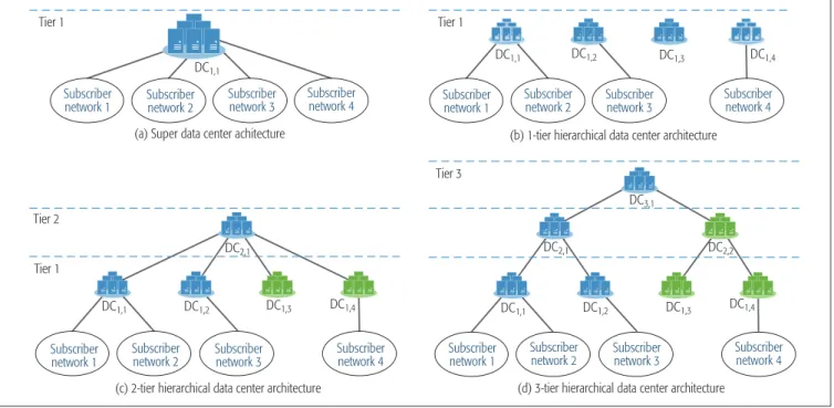
rchItectures The first objective of our emulation experiment is to compare the performances of the conventional super datacenter, the 1-tier (i.e., CORD architec- ture [1]), 2-tier and 3-tier hierarchical architec- tures. The experimental results will reveal how effectively the proposed hierarchical architecture improves the NFV service response time. For fair comparison of these architectures, we fixed the total number of the offered NFV services to 8 and evenly split the first server’s resources into 8 vir- tual machines to run these NFV services. We also created four subscriber networks each generating the traffic in packets of 128 bytes at a fixed rate.Figure 2 illustrates the datacenter network archi-
We have implemented an emulation that captures the major features of the proposed hierarchical datacenter architecture. The emulation is used to evaluate the architecture’s performance in presence
of different traffic patterns and resource allocation strategies.
tectures under investigation.
In the first experiment, we tested the four investigated architectures with a set of traffic rates, 6.4 kb/s, 64 kb/s, 640 kb/s, 6.400 kb/s, 100 Mb/s, and measured the resultant NFV ser- vice response time. Table 2 lists the experiment’s settings, including the propagation delays of inter-datacenter links and the NFV services’ distri- bution over the hierarchical architecture. All the investigated architectures use the same type of fiber optic links such that it takes 5 microseconds to propagate a signal over a 1-km long fiber optic link. The propagation distance from a subscriber network to a super datacenter is set to 2000 km based on the distance between Taipei, Taiwan and the Amazon datacenter in Tokyo, Japan. The propagation distance from a subscriber network to its local Tier-1 datacenter is fixed to 5 km.
However, for fair comparison, the overall propa-
gation distance from a subscriber network to the top tier of the 2-tier or 3-tier architecture is fixed to 2000 km. Table 2 also lists the number of NFV services deployed at each tier of the investigated architecture. For example, each Tier-1 node in the investigated 1-tier hierarchical architecture offers two NFV services, and so on.
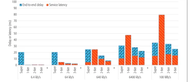
In Fig. 3 we plot the two components of the measured NFV service response time: the average end-to-end delay and the NFV service latency. The former measures the average of the elapsed time from the moment an IP packet is originated from a subscriber network to the moment it arrived at the designated datacen- ter to receive the NFV service. The latter mea- sures the average of the NFV service turnaround times. Figure 3 reveals that when the resource utilization is low, the super datacenter architec- ture suffers from a high end-to-end delay due to FIGURE 2. Four datacenter architectures under investigation.
Tier 1
DC1,1 DC1,1
DC3,1
DC2,1 DC2,1
DC1,1 DC1,2 DC1,3 DC1,4 DC1,1 DC1,2 DC1,3 DC1,4
DC2,2
DC1,2 DC1,3 DC1,4
(a) Super data center achitecture (b) 1-tier hierarchical data center architecture
(d) 3-tier hierarchical data center architecture (c) 2-tier hierarchical data center architecture
Subscriber
network 1 Subscriber
network 2 Subscriber
network 2 Subscriber
network 1 Subscriber
network 3 Subscriber
network 3 Subscriber
network 4 Subscriber
network 4
Subscriber network 2 Subscriber
network 1 Subscriber
network 3 Subscriber
network 4 Subscriber
network 2 Subscriber
network 1 Subscriber
network 3 Subscriber
network 4
Tier 1
Tier 3
Tier 2
Tier 1
TABLE 2. Experiment settings of the investigated datacenter architectures.
Experiment 1
Tier 1 Tier 2 Tier 3
No. of NFV services
Subscriber to Tier 1 propagation
No. of NFV services
Tier 1 to Tier 2 propagation
No. of NFV services
Tier 2 to Tier 3 propagation
Super data center 8 2000 km — — — —
1-tier hierarchical 2 5 km — — — —
2-tier hierarchical 1 5 km 4 1995 km — —
3-tier hierarchical 1 5 km 1 997.5 km 2 997.5 km
Experiment 2 Tier 1 Tier 2 Tier 3
Avg.-dc 1 1 1
Avg.-tier 0.5 1 2
Heavy-feet 1.5 0.5 1
Heavy-head 0.25 0.5 6
the long propagation distance from subscriber networks to the remote super datacenter site.
On the other hand, as the system utilization increases, the CORD architecture’s NFV service latency grows exponentially with the traffic work- load because CORD simply partitions resourc- es among autonomous datacenters without resource sharing. In comparison, the proposed hierarchical datacenter architecture, especially the 3-tier one, stands out from others as it strikes a good balance between centralized processing and edge computing. When operating at a low utilization rate, the hierarchical datacenter archi- tecture behaves just like CORD and benefits from edge computing. On the other hand, each datacenter in the proposed hierarchical architec- ture can always redirect excessive traffic bursts to another underutilized datacenter to reduce the NFV service latency.
h
IerArchIcAlr
esourceA
llocAtIonTo examine the effect of resource allocation on the proposed 3-tier hierarchical datacenter, we re-ran the previous experiment with four different
resource allocation strategies, namely Avg.-dc, Avg.-tier, Heavy-feet and Heavy-head, and three different patterns, S&S, D&S, D&D, as mentioned previously. Table 2 also lists the new NFV ser- vices’ distribution over the 3-tier hierarchical archi- tecture after the adjustment accordingly.
In Fig. 4 we plot the experimental results, showing the percentage of the traffic workload processed at different tiers as well as the average NFV service response time. From the results, the S&S scenario has most traffic workload concen- trating on the first tier. Because redirecting the traffic to an upper tier incurs additional non-trivial propagation delay, under this consideration, the Heavy-feet-like resource distribution is the best suited strategy for the S&S traffic pattern. As for FIGURE 3. Measured average end-to-end delay and NFV service latency.
0 10 20 30 40 50 60 70 80 90 100
Super 1-tier 2-tier 3-tier * Super 1-tier 2-tier 3-tier * Super 1-tier 2-tier 3-tier * Super 1-tier 2-tier 3-tier * Super 1-tier 2-tier 3-tier
6.4 kb/s 64 kb/s 640 kb/s 6400 kb/s 100 Mb/s
Delay or latency (ms)
End-to-end delay Service latency
FIGURE 4. Average NFV service response time (left) and distribution of traffic workload (right) over tiers for each case
0 5 10 15 20 25
Avg. dc Avg. tier Heavy feet Heavy head * Avg. dc Avg. tier Heavy feet Heavy head * Avg. dc Avg. tier Heavy feet Heavy head
S&S D&S D&D
Service response time (milliseconds)
0 10 20 30 40 50 60 70 80 90 100
*
Avg. dc Avg. tier Heav feet
Heavy head
* * Avg. dc Avg. tier Heav feet
Heavy head
* * Avg. dc Avg. tier Heav feet
Heavy head *
S&S D&S D&D
Distribution of traffic workload over tiers (%)
Tier 1 Tier 2 Tier 3
When operating at a low utilization rate, the hierarchical datacenter architecture behaves just like CORD and benefits from edge computing. On the other hand, each datacenter in the proposed hierarchical architecture can always redirect excessive traffic bursts to another underutilized datacenter to reduce
the NFV service latency.
the D&S traffic pattern, the Avg.-dc resource distri- bution is the best suited because traffic flows of a carrier network can traverse through most nodes in the tree overlay network. The Heavy-feet-like resource distribution also fits the D&S traffic pat- tern because most of a tree’s nodes reside on the bottom tier. In the case of the D&D traffic pattern, every traffic must traverse through every tier of two carrier networks; theoretically, the Avg.-tier resource distribution shall be the best choice.
However, its performance advantage is not quite significant.
c onclusIon
In this work, we proposed a hierarchical NFV/
SDN-integrated architecture in which datacen- ters are organized into a multi-tree overlay net- work to collaboratively process user traffic flows.
The proposed architecture is found to be effec- tive and efficient in steering traffic to a nearby datacenter to optimize user-perceived service response time. We have also evaluated through emulation the performances of the proposed hierarchical architecture against the conven- tional super datacenter architecture and the recent CORD architecture. The emulation results showed that the proposed hierarchical architec- ture stands out from the rest because its flexible overlay structure and traffic redirection mecha- nism can exploit the benefits of both centralized processing and edge computing.
The emulation results also reveal that the resource allocation of the proposed hierarchical datacenter architecture shall be decided based on traffic’s source-destination attributes. The
“Heavy-feet”-like resource distribution over the tiers is preferred when most traffic flows within the same edge datacenter. A uniform distribution over the datacenters or over the tiers stands out from others when most traffic flows across a car- rier network or across different carrier networks, respectively.
There are a few open issues that need fur- ther examination. First, it would be of interest to find the Pareto frontier of the resource allocation strategies for the proposed hierarchical datacen- ter architecture subject to different traffic pat- terns. Second, we believe it is possible to further improve the proposed traffic redirection mecha- nism and optimize the overall resource utilization of a carrier network. Last, the evaluation of the proposed architecture in terms of the reliability performance [15] or the quality of experience is complex but crucial and deserves a second article for a thorough investigation.
r
eFerences[1] L. Peterson, “CORD: Central Office Re-Architected as a Datacenter,” IEEE Softwarization eNewsletter, Open Net- working Lab, Nov. 2015, http://sdn.ieee.org/newsletter/
november-2015/cord-central-office-re-architected-as-a-da- tacenter.
[2] J. Dilley et al., “Globally Distributed Content Delivery,” IEE Internet Computing, vol. 6, no. 5, 2002, pp. 50–58.
[3] NFV White Paper — ETSI Portal, https://portal.etsi.org/NFV/
NFV_White_Paper.pdf
[4] R. Szabo et al., “Elastic Network Functions: Opportunities and Challenges,” IEEE Network, vol. 29, no. 3, 2015, pp.
15–21.
[5] AT&T Domain 2.0 Vision White Paper, http://www.att.com/
Common/about_us/pdf/AT&T%20Domain%202.0%20 Vision%20White%20Paper.pdf.
[6] A. Greenberg et al., “VL2: A Scalable and Flexible Data Center Network,” SIGCOMM Computer Communication Review, vol. 39, no. 4, Aug. 2009, pp. 51–62.
[7] J. Mudigonda et al., “NetLord: A Scalable Multi-Tenant Net- work Architecture for Virtualized Datacenters,” Proc. ACM SIGCOMM, Aug., 2011.
[8] T. Benson et al., “CloudNaaS: A Cloud Networking Platform for Enterprise Applications,” Proc. ACM SOCC, June 2011.
[9] ONF, “OpenFlow Switch specification version 1.3.1”, https://www.opennetworking.org/
[10] Ryu SDN Framework, https://osrg.github.io/ryu/
[11] Mininet, http://mininet.org/
[12] Open vSwitch, http://openvswitch.org/
[13] Snort, https://www.snort.org/
[14] Ostinato, http://ostinato.org/
[15] J. Liu et al.,“Reliability Evaluation for NFV Deployment of Future Mobile Broadband Networks,” IEEE Wireless Com- mun., vol. 23, no. 3, 2016, pp. 90–96.
b
IogrAphIesYing-Dar Lin is a distinguished professor at National Chiao Tung University (NCTU). He received his Ph.D. from UCLA in 1993.
He was a visiting scholar at Cisco in 2007–2008. He directs the Network Benchmarking Lab (NBL), an approved lab of the Open Networking Foundation (ONF). His work on “multi-hop cellular” has been highly cited and standardized. He is an IEEE Distinguished Lecturer, and ONF research associate, and serves on several editorial boards. He co-authored Computer Net- works: An Open Source Approach (McGraw-Hill, 2011).
Chih-Chiang Wang is an associate professor at National Kaoh- siung University of Applied Sciences in Taiwan. He received his Ph.D. from North Carolina State University in 2007. His research interests are in the general areas of distributed systems, network protocols, software-defined networking, and wireless networks.
Chien-Ying huang graduated from NCTU and received his Master Degree of Computer Science in 2016. His research interests include distributed systems and software-defined net- working.
Yuan-Cheng Lai received his Ph.D. degree in computer science from NCTU in 1997. He joined the faculty of the Department of Information Management at National Taiwan University of Sci- ence and Technology in 2001, and has been a professor since 2008. His research interests include wireless networks, network performance evaluation, network security, and social networks.