國立臺灣大學工學院機械工程學研究所 博士論文
Department of Mechanical Engineering College of Engineering
National Taiwan University Doctoral Dissertation
變剛性驅動器之發展與應用
Development and Application of Variable Stiffness Actuators
王仁政 Ren-Jeng Wang
指導教授:黃漢邦 博士 Advisor: Han-Pang Huang, Ph.D.
中華民國 101 年 3 月
March 2012
致謝
感謝指導教授 黃漢邦老師創立機器人實驗室,使我在機器人領域能有更加 的認識。感謝論文口試委員小菅一弘教授、王國雄教授、宋震國教授、范光照 教授、蔡得民教授,百忙中能撥空給予我指教與建議。。
感謝實驗室的大家 明輝學長、欽仁、子豪、舉樓、聖諺、博任、柏霆、
啟舜、聖翔、士益,研究期間因有你們而不寂寞。謝謝一直包容我的爸媽,姐 姐,還有我美麗的老婆。最後將這榮耀歸給在天上的父(上帝),感謝上帝的帶領 保守。
敬畏耶和華是智慧的開端
(箴言 9 章 10 節)
摘要
本論文主要的目的,在發展不同於傳統工業機器手臂之擬人形機器手臂整合 系統。此系統將可安裝於為不同目的而設計的機器人平台上,應用於不同環境 中,取代人類或協助人類工作,甚至與人類進行安全的互動行為。
為了研發出一具備上述功能之多自由度擬人形機器手臂整合系統,本論文主
要可分為兩大部分。第一部分將著重於模組化2 軸驅動系統(DAMA)之機構設計
與軟硬體架構建制,並藉由銜接三組該模組化2 軸驅動系統,完成一擬人形 6 軸
機器手臂之建置。而有鑑於傳統的致動器,無法同時滿足操作效能與安全互動之 需求,本論文的第二部分將討論具安全互動行為機制的致動器與設計準則,提出 可以滿足人機安全互動及提升系統效能的主動變剛性彈性驅動系統,並建立具有 此特性之系統廣義線性數學模型,且進一步針對此一模型進行分析與控制器設
計。最後分別設計製作出APVSEA、AVSEA 與 ADEA 可自行調整輸出特性的主
動變剛性彈性驅動器,以分別滿足安全與效能之需求。此設計將可取代傳統致動 器,安裝於任一機器人系統上,以提升系統之性能。除擬人形機器手臂整合系統 外,本文於最後將額外說明主動變剛性彈性驅動系統另一實質應用-手肘關節復 健系統(AVSER)。
未來期許以本論文所發展的主動變剛性彈性驅動器來取代傳統致動器設 計,安裝於所設計製作的多自由度擬人形機器手臂上,達到具有高操作效能仍可 與人類進行安全的互動行為之設計目標。於復健系統則期許發展多關節手腳復健 系統,達到具多關節復健功能之最終目標。
關鍵字:模組化2 軸驅動器、擬人形機器手臂、人機安全互動、主動變剛性彈性
驅動器、手肘關節復健系統
ABSTRACT
This dissertation aims to develop an integrated humanoid robot arm system that can be assembled into robot platforms designed for a variety of purposes, assisting, cooperating, and even interacting with humans in different fields and environments.
The dissertation presents the development of this integrated system in two major parts. The first focuses on developing an integrated system for a vertically intersected dual-axis modularized actuator system (DAMA), which is applied to a 6-axis humanoid robot arm. This section does not carefully consider the safety of human-robot interaction. The second part discusses actuation design, focusing on achieving a proper level of safety in human-robot interaction, and proposes a new actuation approach, active variable stiffness elastic actuation (AVSEA). Several active variable stiffness elastic actuators (APVSEA, AVSEA, ADEA) are designed, offering a compromise between proper safety levels and high manipulation performance. The end section of the dissertation describes another application of active variable stiffness elastic actuators-the elbow rehabilitation system (AVSER).
The research discussed involves the creation of a prototype for an active variable stiffness elastic actuator that has adjustable characteristics. It can be adapted to unknown environments and applied to the creation of a humanoid robot arm system that offers high levels of safety and performance.
Keywords: DAMA, Humanoid Robot Arm, Safety Human-Robot Interaction, Active Variable Stiffness Elastic Actuator, Elbow Rehabilitation System.
CONTENT
摘要...i
Abstract ... iii
List of Tables...ix
List of Figures ...xi
Nomenclature...xv
CHAPTER 1. Introduction...1
1.1. Motivation...1
1.2. Overview of the Dissertation ...3
1.3. Contributions of the Dissertation ...9
CHAPTER 2. Building a Humanoid Robot Arm ...13
2.1. Introduction...14
2.2. Mechanical Design of a DAMA ...19
2.2.1. The Concept of a DAMA...19
2.2.2. Detailed Structure of a DAMA (High Torque Module) ...19
2.2.3. Detailed Structure of a DAMA (Small Size Module) ...22
2.3. Simulation System ...24
2.3.1. The Independent Joint Control of the DAMA System...24
2.3.2. Control and Simulation of the DAMA System ...28
2.4. Finite Element Analysis ...31
2.5. Hardware and Software...32
2.6. Experimental Results ...33
2.7. Summary ...40
CHAPTER 3. Background and Related Work of Inherently Safe Actuating Mechanisms ...41
3.1. Introduction...42
3.2. Performance and Safety Constrains ...44
3.2.1. Performance Indices...44
3.2.2. Safety Criteria ...46
3.3. Pre-existing Compliant and Safety Actuator Design ...50
3.3.1. Cable-and-Cylinder Drive Transmissions...50
3.3.2. Series Elastic Actuators (SEA) ...51
3.3.3. Programmed Impedance Actuators ...53
3.3.4. Variable Stiffness Actuators ...54
3.3.5. Parallel Coupled Micro-Macro Actuators (DM2)...56
3.3.6. Antagonistic Pneumatic Artificial Muscle ...56
3.3.7. Safe Link Mechanism and Safe Joint Mechanism...57
3.4. Summary ...59
CHAPTER 4. APVSEA—An Active-Passive Variable Stiffness Elastic Actuator for Safety Robot Systems...63
4.1. Introduction...64
4.2. Precise Position Movement Actuation / Safe Actuation ...65
4.2.1. Motor-Ball screw Drive System ...65
4.2.2. Passive Variable Stiffness Serial Configuration...66
4.2.3. Active Variable Stiffness Serial Configuration ...67
4.2.4. Active-Passive Variable Stiffness Elastic Actuator (APVSEA)...69
4.3. Design of an Active-Passive Variable Stiffness Elastic Actuator (APVSEA) ...71
4.4. System Experiment Evaluation...75
4.4.1. Adaptive Compliant Property ...75
4.4.2. Active Variable Stiffness Property ...78
4.4.3. Safe Robot System...79
4.5. Summary ...80
CHAPTER 5. AVSEA—Active Variable Stiffness Elastic Actuator:Design and Application for Safe Physical Human-Robot Interaction ...83
5.1. Introduction...84
5.2. Precise Position Movement Actuation / Safe Actuation ...84
5.2.1. Motor-Ball screw Drive System ...85
5.2.2. Active Variable Stiffness Serial Configuration ...88
5.2.3. Active Variable Stiffness Elastic Actuator (AVSEA)...90
5.3. Design of an Active Variable Stiffness Elastic Actuator...91
5.4. System Experiment Evaluation...96
5.4.1. Adaptive Compliant Property ...96
5.4.2. Active Variable Stiffness Property ...98
5.4.3. Response to Position Command with Variable Stiffness ...98
5.4.4. Head Injury Criterion (HIC) ...100
5.5. Summary ...102
CHAPTER 6. ADEA—Active Variable Stiffness Differential Elastic Actuator: Design and Application for Safe Robotics...103
6.1. Introduction...104
6.2. General Idea of the Active Variable Stiffness Differential Elastic Actuator
(ADEA)...105
6.2.1. Active Variable Stiffness Element - Leaf spring ...105
6.2.2. Mathematical Description of the Active Variable Stiffness Differential Elastic Actuator (ADEA) ...106
6.3. Design, Working Principle and Modeling of the ADEA...108
6.3.1. Mechanical Design and Working Principle...109
6.3.2. Mechanism Modeling of the ADEA System... 111
6.3.3. Analysis of the ADEA System... 113
6.4. System Experiment Evaluation... 115
6.4.1. Adaptive Compliant Property of ADEA ... 116
6.4.2. Active Variable Stiffness Property of ADEA... 117
6.4.3. Response to Position Command with Variable Stiffness ... 118
6.4.4. Head Injury Criterion (HIC) ... 119
6.5. Summary ...121
CHAPTER 7. Application:Rehabilitation System ...123
7.1. Introduction...124
7.2. New Rehabilitation Robot System—Active Variable Stiffness Exoskeleton Robot (AVSER)...128
7.3. Principle and Design of the Active Variable Stiffness Elastic Exoskeleton Robot (AVSER)...130
7.4. System Experiment Evaluation...130
7.5. Summary ...137
CHAPTER 8. Conclusions and Future Works ...139
8.1. Conclusions...139
8.2. Future Works...140
8.2.1. Active Variable Stiffness Elastic Actuator ...141
8.2.2. Humanoid Robot System Design...141
8.2.3. Rehabilitation System ...142
8.2.4. Exoskeleton System ...142
References...144
LIST OF TABLES
Table 2-1 Specification of the DAMA...34
Table 2-2 Specification of the 6-axis humanoid robot arm...37
Table 4-1 Specification of the APVSEA...77
Table 4-2 The Estimated HIC and vmax for APVSEA and SEA...80
Table 5-1 Specification of AVSEA ...97
Table 6-1 Specification of the ADEA ... 115
Table 7-1 Specification of the AVSER...132
LIST OF FIGURES
Figure 2-1 Poly Bot [2] ...15
Figure 2-2 Micro-robot [6]...15
Figure 2-3 Odin [8] ...16
Figure 2-4 Modular Robot [9]...16
Figure 2-5 KRVM [10] ...16
Figure 2-6 Roombots [16]...16
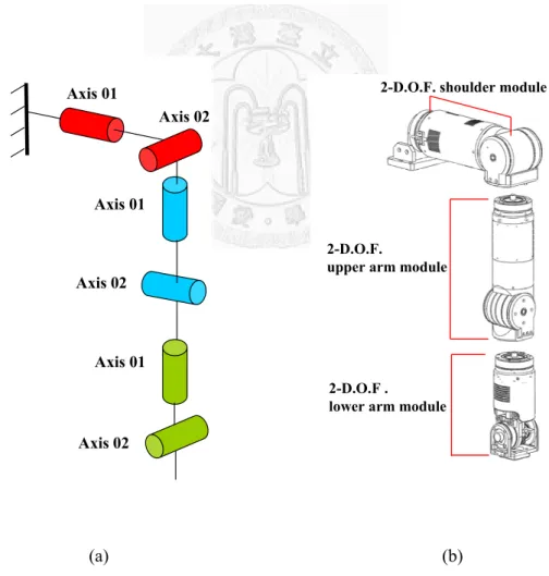
Figure 2-7 (a) The kinematics of the 6-axis humanoid robot arm, and (b) the concept of the 6-axis humanoid robot arm with three DAMAs...18
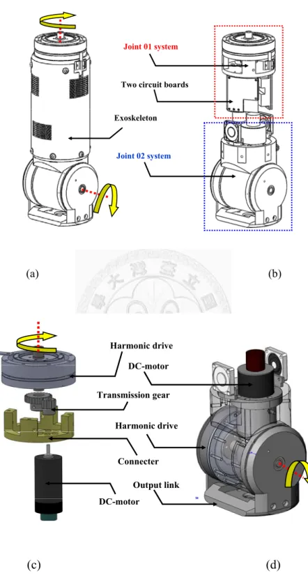
Figure 2-8 The Vertically Intersected Dual Axes Modularized Actuator System (DAMA) with high torque capability: (a) the DAMA outward appearance, (b) the detailed structure of the DAMA, (c) the Joint 01 system of the DAMA, and (d) the Joint 02 system of the DAMA. ...21
Figure 2-9 The Vertically Intersected Dual Axes Modularized Actuator System (DAMA) with small size capability: (a) the DAMA outward appearance, (b) the detailed structure of the DAMA, (c) the Joint 01 system, and (d) the Joint 02 system. ...23
Figure 2-10 (a) The Simulation System of the DAMA, and (b) the ADAMS software Simulation System. ...29
Figure 2-11 Simulation results and the average tracking errors: (a) the joint 01 system of the DAMA, and (b) the joint 02 system of the DAMA...30
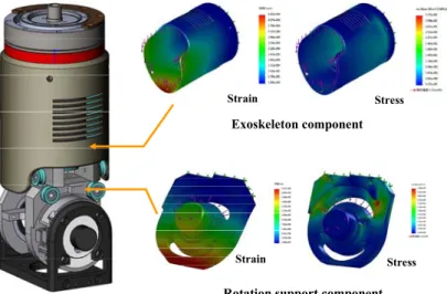
Figure 2-12 Finite element analysis of two key components of the DAMA. ...32
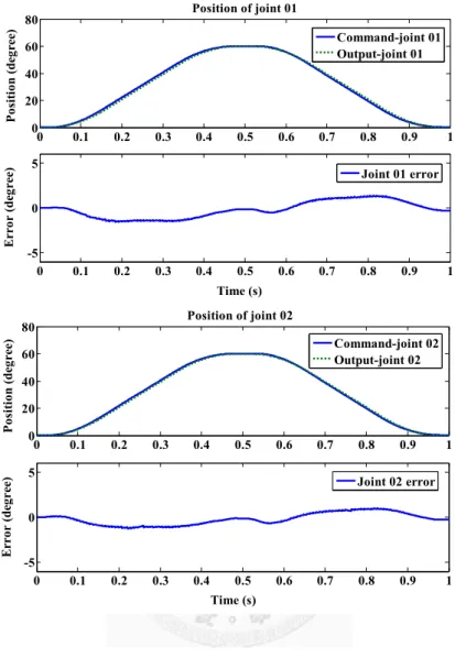
Figure 2-13 (a) Experimental setup for the DAMA, and (b) the angular positions and the error curves of two independent joints of the DAMA. ...35
Figure 2-14 The Workspace of the 6-axis robot arm. ...37
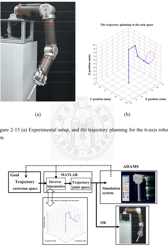
Figure 2-15 (a) Experimental setup, and (b) trajectory planning for the 6-axis robot arm...38
Figure 2-16 The 6-axis humanoid robot arm simulation and control system. ...38
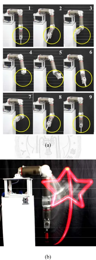
Figure 2-17 Experimental results: (a) the 6-axis humanoid robot arm with circle motion, and (b) the 6-axis humanoid robot arm with five-angle star motion. ...39
Figure 3-1 Head injury criteria as a function of effective inertia and interface stiffness [40]...49
Figure 3-2The Barrett WAM robot [42]...51
Figure 3-3 Different kinds of Series Elastic Actuators. ...53 Figure 3-4 Mechanical Impedance Adjuster where linear spring and brake
systems are directly built [54][58] ...55
Figure 3-5 Appearance of the Variable Stiffness Actuator [61] ...55
Figure 3-6 An Actuator with Mechanically Adjustable Series Compliance [52]...55
Figure 3-7 Distributed Elastically Coupled Macro Mini Actuation (DECMMA) [40]...58
Figure 3-8 Artificial muscles in antagonistic pairs ...58
Figure 3-9 Prototype and operation of the safe joint mechanism [84] ...58
Figure 4-1 Motor-Ball screw Drive System...67
Figure 4-2 Passive variable stiffness serial configuration. ...67
Figure 4-3 Active Variable Stiffness Serial Configuration. ...70
Figure 4-4 The relationship between the block movement and the force on the block...70
Figure 4-5 The relationship between the block movement and the force on the block...70
Figure 4-6 3D model of Active-Passive Variable Stiffness Elastic Actuator. ...73
Figure 4-7 Front view of Active-Passive Variable Stiffness Elastic Actuator...74
Figure 4-8 3D model of Main structure of APVSEA. ...74
Figure 4-9 3D model of Main structure of APVSEA when APVSEA with external forces...74
Figure 4-10 Active-Passive Variable Stiffness Elastic Actuator (APVSEA). ...77
Figure 4-11 Adaptive compliant property for Active-Passive Variable Stiffness Elastic Actuator. ...77
Figure 4-12 Response to position command with various stiffness...78
Figure 4-13 Measure stiffness of the APVSEA. ...78
Figure 4-14 Experiment setup for hitting-object experiment. ...80
Figure 5-1 Motor-Ball screw Drive System...87
Figure 5-2 A block assembly (with propelling shave and fixed pulley). ...87
Figure 5-3 New Motor-Ball screw Drive System (with block assembly)...88
Figure 5-4 A beam system...89
Figure 5-5 Schematic of active variable stiffness serial configuration. By changing the position of the moving plant, the active variable stiffness serial configuration has ability to obtain the effective length of leaf spring (
l
), change of the effective length of the leaf spring results in changing stiffness...89Figure 5-6 A concept of the Active Variable Stiffness Elastic Actuator (AVSEA). ...90 Figure 5-7 Control topology of the AVSEA. The AVSEA consists of two
DC-motors: one is used to control the position of the joint and the other is used to adjust the stiffness of the APVSEA. Each motor is
controlled by a simple PID controller. ...90
Figure 5-8 3D model of Active Variable Stiffness Elastic Actuator (AVSEA)...93
Figure 5-9 Top view of AVSEA (3-D model of new motor-ball screw drive system) ...93
Figure 5-10 3-D model of active variable stiffness serial configuration of AVSEA ...94
Figure 5-11 3D model of the Motor-Ball screw drive system of AVSEA; (a) the concept of the Motor-Ball screw drive system of AVSEA, (b) the cross-section diagram of the Motor-Ball screw drive system of AVSEA, (c) the detail structure of the Motor-Ball screw drive system of AVSEA, (d) the Motor-Ball screw drive system of AVSEA with external forces...94
Figure 5-12 Active Variable Stiffness Elastic Actuator (AVSEA). ...97
Figure 5-13 Adaptive compliant property for Active Variable Stiffness Elastic Actuator...99
Figure 5-14 Measure stiffness of the AVSEA...99
Figure 5-15 Response to position command with variable stiffness. ...100
Figure 5-16 The head Injury Criterion (HIC) for SEA and AVSEA. An HIC of 100 is a suitable value to normal operation of a machine physically interacting with humans. The model parameters for AVSEA are: Maximum Ktransm =3000kN/m (Equivalent to rigid joint stiffness), Minimum Ktransm=0.95kN/m, γ=3000kN/m, Kcov =25kN/m, Moper=4kg, rotor M =0.7kg and Mlink=0.5kg. ...102
Figure 6-1 The Active Variable Stiffness Differential Elastic Actuator (ADEA)...104
Figure 6-2 The Concept of a Beam System. ...106
Figure 6-3 The four bar linkage system of the ADEA...108
Figure 6-4 The symmetric roller system of the ADEA...108
Figure 6-5 The detail structure of the ADEA... 110
Figure 6-6 3D model of the ADEA... 111
Figure 6-7 A Simplified ADEA Model. ... 112
Figure 6-8 Simulation Frequency Response with End Free. ... 114
Figure 6-9 Simulation Frequency Response without any Actuator Force. ... 115
Figure 6-10 Active Variable Stiffness Differential Elastic Actuator (ADEA). ... 116
Figure 6-11 Adaptive compliant property for the ADEA... 117
Figure 6-12 Measure stiffness of the ADEA... 119
Figure 6-13 Response to position command with variable stiffness. ... 119 Figure 6-14 The head Injury Criterion (HIC) for SEA and ADEA. An HIC of 100
is a suitable value to normal operation of a machine physically interacting with humans. The model parameters for ADEA are:
Maximum Ktransm =3000kN/m (Equivalent to rigid joint stiffness), Minimum Ktransm=0.95kN/m, γ=3000kN/m, Kcov =25kN/m, Moper=4kg,
rotor
M =0.7kg and
Mlink=0.5kg. ...121 Figure 7-1 The Active Variable Stiffness Exoskeleton Robot System...129 Figure 7-2 Rehabilitation Robot System...129 Figure 7-3 3D model of AVSEA ...131 Figure 7-4 3D model of AVSER. ...131 Figure 7-5 Active Variable Stiffness Exoskeleton Robot System (AVSER)...133 Figure 7-6 Rehabilitation exercise setup...133 Figure 7-7 Active Variable Stiffness Exoskeleton Robot System (AVSER)...134 Figure 7-8 Experiment results of different rehabilitation exercise modes...137 Figure 8-1 The multi-Axial rehabilitation system (a) 3D model of the system, (b)
The system has elastic elements and functions of variable stiffness to meet the demand for safe upper limbs rehabilitation...142
NOMENCLATURE Notations
e
b Back electromotive forcef
eff Effective viscous friction coefficient of the combined motor and load referred to the motor shaftf
m Viscous-friction coefficient of the motor referred to the motor shaftf
L Viscous-friction coefficient of the load refered to the load shafti
a Armature currentJ
eff Effective moment of inertia of the f the combined motor and load referred to the motor shaftJ
L Moment of inertia of the load refered to the load shaftJ
m Moment of inertia of the motor referred to the motor shaftK
a Torque constant of the motorK
b Back emf constantK
p Position feedback gainK
v Error derivative feedback gainK
I Integral gainL
a Armature inductancen
Reduction ratio of the gear trainR
a Armature resistanceV
a Applied voltageθ
m Angular displacements of the motor shaftθ
L Load shaft in radianτ
Torque delivered by the motor τ m Torque dissipated by the motor τ L Load torque referred to the load shaft*
τ
L Torque dissipated by the load referred to the motor shaftAcronyms
ADEA Active Variable Stiffness Differential Elastic Actuator APVSEA Active-Passive Variable Stiffness Elastic Actuator AVSEA Active Variable Stiffness Elastic Actuator
AVSER Active Variable Stiffness Exoskeleton Robotic System
DAMA A Vertically Intersected Dual Axes Modularized Actuator System
DOF Degree of Freedom
DECMMA Distributed Elastically Coupled Macro Mini Actuation EMG Electromyogram
HIC Head Injury Criterion
SEA Series Elastic Actuator
SJM Safe joint mechanism
SLM Safe link mechanism
CHAPTER 1. INTRODUCTION
1.1. Motivation
The field of robotics currently involves a wide range of applications that can be employed in different fields and environments. One of the most important issues in modem robotics, and also one of the most challenging, is to make robots more versatile in terms of their ability to handle unpredictable and difficult tasks. A great amount of research has been carried out that aims to enhance the dexterity and functionality of robots. The development of an integrated system for a humanoid robot arm, taking into account mechanical design, solvability of kinematics, trajectory generation, control theorems, and a compromise between safety and performance, is thus critical. An excellently designed humanoid robot arm system can be assembled and integrated into either a movable platform or a fixed platform to fulfill diverse tasks.
The development of a humanoid robot system involves the following two areas:
(1) Hardware Design
Hardware design involves mechanical and control architecture design, seriously
influencing operation performance as well as other crucial issues. Mechanical design, involving mechanical component design, arrangement of actuators and sensors, distribution of masses, and analyses of kinematics and dynamics, is crucial to the performance of a humanoid robot. Control architecture design, involving control and communication modules, motor signal process modules, driver modules, and sensor systems, is also crucial, particularly with regard to real-time performance and control algorithm realization. An overall control system can be divided into several sub-systems, each designed for different purposes that suit a variety of potential situations.
(2) Software Development
The software used by a humanoid robot arm, which includes a user interface, control algorithm, trajectory planning, and task planners, determines its responses.
Integrated industrial manipulator systems that take both hardware and software design into account have long existed, whereas humanoid robots that are able to physically assist humans in various environments are still being developed. Most existing unfolding robot arms have only one design consideration, such as performance or safety. This integrative humanoid robot system, consisting of rigid links, electrical
1.2 OVERVIEW OF THE DISSERTATION
only interact with people and environments under safety constraints, and moves slowly through carefully planned motions, applying multiple control strategies.
Human-robot-environment interaction includes a wide range of applications, and may involve robots operating in unstructured environments, sharing workspaces, and engaging in close physical cooperation with humans, which means that safety issues are a primary concern.
1.2. Overview of the Dissertation
This dissertation is divided into two main parts. The first part, presented in Chapter 2 focuses on developing the integrated system for a rigid humanoid robot arm without carefully considering the safety level of human-robot interaction. The second part, which presented in Chapters 3 through 6, concentrates on the development of an alternative actuation approach, and of critical modular mechanism components, making compromises that allow humanoid robot arms to interact with people and execute complex motions safely in unstructured environments. In Chapter 7, another application of active variable stiffness elastic actuators, the elbow rehabilitation system (AVSER), is described. Chapter 8 presents conclusions and directions for future work.
The chapters in this dissertation can be briefly described as follows:
Chapter 1 Introduction
This chapter gives a brief statement about the motivation, overview, and contributions of this dissertation, and discusses essential elements of the construction of an integrated humanoid robot arm system from the broad perspective of modern robotics.
Chapter 2 Building a Humanoid Robot Arm
The beginning of this chapter describes current robotics technology, focusing especially on the design of robot manipulators. This dissertation develops a vertically intersected dual-axis modularized actuator system (DAMA), and applies it to a 6-axis humanoid robot arm. This DAMA system consists of two independent joints, and is refined using finite element analysis. In this chapter, it is demonstrated how a novel DAMA modular system can be used to easily construct a mechanism with any degree of freedom, achieving a modular or reconfigurable system by using the DAMA module. The system’s dynamic properties are observed based on simulations with ADAMS and MATLAB software packages. This chapter also covers the development of the hardware and software systems of the DAMA. The hardware architecture is composed of a microprocessor, an RS-232 to CAN Bus Module, and two
1.2 OVERVIEW OF THE DISSERTATION
independent-joint controller modules. The software control system is written in Visual C++. The system employs a simple but effective PID scheme to independently control the DAMA’s two joints. The experimental results show that for an S curve and circle trajectory input position command, the DAMA and the 6-axis humanoid robot arm, which is formed by the DAMA module, are able to effectively track commands. This means that the DAMA can be used as a generic module for multiple-degrees-of-freedom systems.
Chapter 3 Background and Related Work of Inherently Safe Actuating Mechanisms
In this chapter, the focus shifts to a different field, that of human-robot interaction, with the aim of developing an intrinsically-safe method of robot actuation and a control strategy that takes both capacity for performance and safety of motion into account. Critical qualitative and quantitative indices for measuring performance and safety are discussed, with reference to the evaluation and development of a robotic system and actuator design. A brief introduction to pre-existing compliant actuators and their design concepts is also presented.
Chapter 4 APVSEA - An Active-Passive Variable Stiffness Elastic Actuator for Robot System Safety
In classical robotics applications, robotic systems consist of servo motors, as well
as high-ratio reduction and rigid links. Mechanical designers prefer to design robotic applications that are as stiff as possible, so that robots can be manipulated with greater speed and precision. Unfortunately, such robotic applications are often unable to meet safety requirements in their interactions with people, and in environments where the safety of humans and protection of robots is fundamental. This dissertation presents an active-passive variable stiffness elastic actuator (APVSEA) which is designed for safe robot systems. The APVSEA consists of two DC motors. One is used to control the position of the robot’s joint, while the other is used to adjust the stiffness of the system. Stiffness is generated by two antagonistically nonlinear springs, and by changing the preload length of the springs, the APVSEA is able to minimize heavy forces of impact due to shocks, safely interact with the user, and become as stiff as is needed to make precise position movements and trajectory tracking control easier.
This chapter presents experiment results to show that the APVSEA is capable of allowing both precise position movements and safe human-robot interaction.
Chapter 5 AVSEA- Active Variable Stiffness Elastic Actuator: Design and Application for Safe Human-Robot Physical Interaction
This dissertation also presents an active variable stiffness elastic actuator (AVSEA) that is designed to allow for safe human-robot physical interaction. The
1.2 OVERVIEW OF THE DISSERTATION
the other is used to adjust the stiffness of the system. The stiffness is generated by a leaf spring. By changing the effective length of the leaf spring, the AVSEA has the ability to minimize the force of heavy impacts due to shocks, safely interact with users, and become as stiff as necessary to more easily allow precise position movements and trajectory tracking control. Experimental results are presented to show that AVSEA is capable of enabling precise position movements to be carried out while also ensuring safe human-robot interaction.
Chapter 6 ADEA- Active Variable Stiffness Differential Elastic Actuator:
Design and Application for Robot Safety
In addition to the above, this dissertation presents an active variable stiffness differential elastic actuator (ADEA) that is designed for application in robotic systems and, more generally, in machines designed to interact with people and environments under safety constraints. The ADEA consists of two DC motors that independently drive two antagonistic warm gears. By changing the synchronization and differentiation in angle displacement of these two gears, the ADEA has the capacity to minimize heavy impacts due to shocks, safely interact with users, and become as stiff as is necessary to make precise position movements. In addition, the ADEA allows for fast motion control while guaranteeing the safety of human operators in worst-case impact situations through its dynamically variable stiffness. This chapter presents
experimental results to demonstrate the performance and safety capabilities of a one-link arm actuated by the ADEA.
Chapter 7 Application: Rehabilitation System
The dissertation introduces an active variable stiffness exoskeleton robotic system (AVSER) with the AVSEA, improving the safety of human-robot interaction and produces a unique capacity for adjustable stiffness that meets demands for safe active-passive elbow rehabilitation. The AVSEA consists of two DC motors. One is used to control the position of the joint, while the other is used to adjust the stiffness of the system. The stiffness is generated by a leaf spring. By shortening the effective length of the leaf spring, the AVSEA is able to reduce stiffness automatically, which moves the AVSER from active (assistive) motion to passive (resistance) rehabilitation during the process of therapy. In this chapter, the mechanical design, modeling, and control algorithms are described in detail. The capacity of the proposed AVSER with electromyogram (EMG) signal feedback is verified through rehabilitation exercise experiments to demonstrate the efficacy of the system.
Chapter 8 Conclusions and Future Work
This chapter briefly gives a summary of the dissertation, offers some concluding remarks and outlines work to be carried out in the future.
1.3 CONTRIBUTIONS OF THE DISSERTATION
1.3. Contributions of the Dissertation
The contributions of this dissertation are
(1) Design of a Vertically Intersected Dual-Axis Modularized Actuator System
The dissertation presents the design of a vertically intersected dual-axis modularized actuator system (DAMA) and its application to a 6-axis humanoid robot arm. This DAMA system possesses some special characteristics, including the following:
• Each DAMA consists of a pair of two DOF atoms, with two units.
• Each DAMA has an on-board microprocessor and communication system.
• Each DAMA has the ability to connect to, disconnect from, and rotate around its neighbors.
• Each DAMA possesses enough power to rotate its neighbors.
• The shape of the DAMA is in pot form, mimicking the appearance of a human arm.
(2) Design of a 6-Axis Humanoid Robot Arm
As part of this dissertation, a 6-axis humanoid robot arm has been built, which consists of three DAMAs, two high torque modules for the shoulder and upper part, and one small module for the lower part. The arm possesses some special
characteristics, such as:
• Human form, allowing it to work with objects designed for people more easily.
• Human-like structure and integration of simple kinematics.
• Partial utilization of harmonic drives, improving precision and efficiency.
• Quick and flexible construction.
• Simple wire systems, constructed using DAMAs.
These characteristics can also serve as useful design objectives for the development and examination of more advanced theories and algorithms.
(3) Development of Actuation Compromise between Safety and Performance
Several intrinsically safe intelligent actuators have been designed, which ensure both high performance and safe motion capacities. A linear model and a series of manipulations have been used to check the performance of the system and its benefits for designers.
(4) Design of Intrinsically Safe Intelligent Actuator Mechanisms
By changing the stiffness of actuators, the system is able to minimize high impact forces due to shocks, safely interact with users, and become as stiff as is
1.3 CONTRIBUTIONS OF THE DISSERTATION
dissertation presents an APVSEA whose stiffness is generated by two antagonistically nonlinear springs, an AVSEA whose stiffness is generated by a leaf spring, and an ADEA whose stiffness is generated by the synchronization and differentiation of angle displacement in two antagonistic warm gears. These intrinsically safe intelligent actuators allow for high performance within safety constraints.
(5) Design of Rehabilitation System Mechanism
The dissertation introduces an AVSER with the AVSEA, which improves the safety of human-robot interaction and produces a unique capacity for adjustable stiffness that meets safe active-passive elbow rehabilitation demands. The mechanical design and control algorithms are described in detail. The capacity of the proposed AVSER with electromyogram (EMG) signal feedback is verified through rehabilitation exercise experiments that demonstrate the efficacy of the system.
CHAPTER 2. BUILDING A HUMANOID ROBOT ARM
A Vertically Intersected Dual-Axis Modularized Actuator System (DAMA) is developed and applied to a 6-axis humanoid robot arm in this dissertation. The DAMA consists of a two-independent-joint system, and the system structure is further refined using finite element analysis. It will be shown that the novel DAMA modular system can be used to easily construct a mechanism with any degrees of freedom. In other words, a modular or reconfigurable system can be achieved using the DAMA module. Based on simulations with ADAMS and MATLAB software packages, the system dynamic properties can be observed. In addition, the hardware and software systems of the DAMA are developed. The hardware architecture is composed of a microprocessor, an RS-232 to CAN Bus Module, and two independent-joint controller modules. The software control system is written in Visual C++. The system employs a simple but effective PID scheme to independently control the DAMA’s two joints.
The experimental results show that for an S curve and circle trajectory input position command, the DAMA and the 6-axis humanoid robot arm, which is formed by the
DAMA module, can track the command well. Hence, the DAMA can be used as a generic module for multiple-degrees-of-freedom systems
2.1. Introduction
A modular robot can be defined as a robotic system constructed from a set of standard components. Modular robots are of interest because they permit the construction of a wide variety of specialized robots from a set of standard components.
Due to the adaptability of the modular robot, it can pass through narrow passageways, reshape itself into a legged robot and walk over rubble, and climb stairs or even on desks by self-reconfiguration. Another application is space/planetary exploration, where unpredictable terrains on a planet have to be explored by a robot before human beings are sent. There are two types of connection methods between modules, manual and self-reconfigurable.
For the manual type, two modular reconfigurable robots are connected by the user; and various types of modular systems have been proposed, CEBOT [1], PolyPod [2][3], Tetrobot [4], RBR [5], Micro-robot [6], Modular Robot Manipulators with Preloadable Modules [7], Odin [8], New Independently-Mobile Reconfigurable Modular Robot [9]. Less effort has been made in the field of self-reconfigurable modular robots, which can autonomously change their configurations. The modular
2.1 INTRODUCTION
self-reconfigurable robot is proposed in order to make the system adaptable to different given tasks and unknown environments. Several self-reconfigurable robots have been proposed, KRVM [10], Modular Robotic System [11], Self-reconfigurable robots [12], M-TRAN [13], Switchable bonding mechanism [14], [15], Roombots [16]. In the studies above, the software and hardware designs of the module are important issues. In recent years, humanoid robot technology has gradually matured.
The main purpose of humanoid robots is to help people in operations, or even to replace people in dangerous jobs, such as repairing machines, experimenting with chemical treatments, and achieving precision in work. In humanoid robot arms design, many researchers have focused on developing a 6-axis robot arm that looks like a human arm. HRP [17], BHR-01 [18], KHR-3 [19], MAHRU [20], and BHR-02 [21]
are well-known 6-axis human-size humanoid robot arms. However, in those robots, the structures of the robot arms are complex.
Figure 2-1 Poly Bot [2] Figure 2-2 Micro-robot [6]
Figure 2-3 Odin [8] Figure 2-4 Modular Robot [9]
Figure 2-5 KRVM [10] Figure 2-6 Roombots [16]
In addition, the development of microprocessors, microelectronics, and communication method, proceeds very rapidly. A humanoid robot consists of a multiple-degree-of-freedom mechanism, and is very complicated. Some robots have been designed with centralized control architectures, such as IEEE-1394, local ISA, VME, RS-232, and PCI bus. Their communication interfaces have high communication speed, but the wire systems are too heavy and complicated. Other robots have been designed with distributed control architecture using CAN-Bus [22],
2.1 INTRODUCTION
Ethernet [23], or Ethernet-CAN-USB [24] to achieve real-time control.
The goal of this dissertation is to design a Vertically Intersected Dual Axes Modularized Actuator System (DAMA) with CAN-Bus communication system that can build humanoid robot arm systems more flexibly and quickly with low manufacturing and maintenance costs. The kinematics of the 6-axis humanoid robot arm is shown in Figure 2-7(a) and the concept of the 6-axis humanoid robot arm with three DAMAs is shown in Figure 2-7(b). Therefore, we consider the following parameters:
z Each DAMA consists of a pair of two-DOF atoms (with two units).
z Each DAMA has an on-board microprocessor and communication system.
z Each DAMA has ability to connect, disconnect and rotate around its neighbors.
z Each DAMA can offer enough power to rotate its neighbors.
z The shape of each DAMA is in a pot form to mimic the appearance of a human arm.
z The robot arms which consist of DAMAs can be constructed quickly and flexibly.
z The wire systems of the robot arms constructed using DAMAs are simple.
This chapter is structured as follows. Section 2 presents the main idea of a DAMA, and the mechanical structure and properties of the DAMA will be introduced.
Dynamic simulation of the DAMA is shown in Section 3. In Section 4, finite element analysis for the key components of the DAMA is briefed. The hardware and software of the DAMA control system are discussed and implemented in Section 5. Section 6 presents experimental results to show that each joint of DAMA is capable of providing precise position movement. Finally, summary are made in Section 7.
(a)
Axis 01
Axis 02
Axis 02 Axis 01
Axis 01
Axis 02
2-D.O.F. shoulder module
2-D.O.F.
upper arm module
2-D.O.F .
lower arm module (b)
(a) (b)
Figure 2-7 (a) The kinematics of the 6-axis humanoid robot arm, and (b) the concept of the 6-axis humanoid robot arm with three DAMAs.
2.2 MECHANICAL DESIGN OF A DAMA
2.2. Mechanical Design of a DAMA
A modular robot can be defined as a robotic system constructed from a set of standard components. Modular robots are of interest because they permit the construction of a wide variety of specialized robots. In this section, the concept and the detailed structure of the DAMA are presented.of the DAMA are presented.
2.2.1. The Concept of a DAMA
The main concept of a DAMA is a vertically intersected, dual-axis structure and some specific designs make it modularized. It can serve as a modular two-axis actuator. Hence, a multiple-degree-of-freedom (DOFs) mechanism, such as humanoid robot arms, can be configured in terms of a DAMA. However, for a humanoid robot system, each part has its unique standards. For example, in a humanoid robot arm, the shoulder part is focused on high power and high torque, but the wrist part should pay attention to the size of the mechanism. To satisfy such requirements, two types of DAMAs, a high torque module and a small size module, will be developed in this dissertation.
2.2.2. Detailed Structure of a DAMA (High Torque Module)
The DAMA with high torque capability is composed of four parts: the Joint 01 system, the Joint 02 system, an exoskeleton, and two circuit boards, as shown in
Figure 2-8(a) and Figure 2-8(b). Joint 01 and Joint 02 form two independent axes.
Namely, the DAMA is characterized by dual axes, high output torque, and precise position movement. In order to mimic the appearance of a human arm, the shape of a DAMA is in a regular pot form. Therefore, it is a big challenge to arrange all components in such a particular space.
Joint 01 System
Joint 01 of the DAMA with high torque capability consists of a harmonic drive, a transmission gear, a connector, and a DC-motor. The DC-motor is fixed on the connector, and a transmission gear is driven and rotated by the DC-motor. Hence, the harmonic drive, which is connected to the transmission gear, will be driven and then the output link be rotated, as shown in Figure 2-8(c).
Joint 02 System
Similar to Joint 01, joint 02 of DAMA with high torque capability is mainly composed of a harmonic drive, a transmission gear, a connector, and a DC-motor. To fit some components in the exoskeleton to shape the DAMA like a drum, the DC-motor of the Joint 02 system is installed on the side and parallel to the DC-motor of Joint 01. The transmission gear is used to drive and rotate the harmonic drive, and the output link is rotated, as shown in Figure 2-8(d).
2.2 MECHANICAL DESIGN OF A DAMA
Joint 02 system Joint 01 system
Exoskeleton Two circuit boards
(b) (a)
(a) (b)
Harmonic drive DC-motor
Transmission gear
DC-motor Harmonic drive
Connecter Output link
(d) (c)
(c) (d)
Figure 2-8 The Vertically Intersected Dual Axes Modularized Actuator System (DAMA) with high torque capability: (a) the DAMA outward appearance, (b) the detailed structure of the DAMA, (c) the Joint 01 system of the DAMA, and (d) the Joint 02 system of the DAMA.
Exoskeleton
The DAMA has two independent rotation systems. The exoskeleton is used to connect the Joint 01 system and the Joint 02 system in order to form a complete two-axis actuator. The exoskeleton is made of aluminum to reduce the weight of DAMA, and keeps joint 01 and joint 02 systems in the right location
2.2.3. Detailed Structure of a DAMA (Small Size Module)
The DAMA with small size capability is composed of five main parts: the Joint 01 system, the Joint 02 system, a tension adjuster, an exoskeleton, and two circuit boards, as shown in Figure 2-9(a) and (b). Joint 01 and Joint 02 form two independent axes. Namely, the DAMA is characterized by dual axes, precise position movement, and easy control.
Joint 02 System
Joint 02 of the DAMA with small size capability is a cable driven system, as shown in Figure 2-9(c). In the cable system, a screw, a DC-motor and a cable are connected. The cable passes through a pulley system and connects to the tension adjuster. When the DC-motor drives the screw, the cable fixed on the screw is pulled, and the output link is rotated by the connection of the cable to the tension adjuster.
2.2 MECHANICAL DESIGN OF A DAMA
Joint 02 system Joint 01 system
Exoskeleton
Two circuit boards (a) (b)
(a) (b)
DC-motor
Output link Pulley system
Tension adjuster Screw (c)
Moving plant Screw
Cable Turntable
(c) (d) Figure 2-9 The Vertically Intersected Dual Axes Modularized Actuator System
(DAMA) with small size capability: (a) the DAMA outward appearance, (b) the detailed structure of the DAMA, (c) the Joint 01 system, and (d) the Joint 02 system.
Tension Adjuster
To keep Joint 02 as stiff as possible with precise position movement, a tension adjuster is designed to adjust the cable tension, as shown in Figure 2-9(d). The tension adjuster consists of a turntable, two antagonistic screws, and two moving plants. Each moving plant is fixed on the screw, and one end of the cable is fixed on the moving plant. By turning the screw, the moving plant will move to adjust the cable tension.
2.3. Simulation System
In this dissertation the MATLAB/Control software and ADAMS/Simulation are integrated to simulate the dynamic behaviors of the DAMA system.
2.3.1. The Independent Joint Control of the DAMA System
Most robot manipulators are electrically actuated. Electrically driven manipulators are constructed with a DC permanent magnet torque motor for each joint.
The motor shaft is coupled to a gear train to the load of the link. So the relationship between motor shaft and load shaft can be described as
1
L m
θ n
θ
= < , (2-1)where
n
is the reduction ratio of the gear train andθ
m andθ
L are the angular displacements of the motor shaft and load shaft in radian respectively. When a load is2.3 SIMULATION SYSTEM
attached to the output gear, the torque developed at the motor shaft can be described as
( )
t
m( )t
*L( )t
τ
=τ
+τ
, (2-2)where ( )
τ t
is the torque delivered by the motor,τ
m( )t
is the torque dissipated by the motor, andτ
L*( )t
is the torque dissipated by the load referred to the motor shaft.The motor torque referred to the motor shaft
τ
m( )t
and the load torque referred to the load shaftτ
L( )t
can be written as( ) ( ) ( )
m
t J
m mt f
m mt
τ
=θ
&& +θ
& , (2-3)( ) ( ) ( )
L
t J
L Lt f
L Lt
τ
=θ
&& +θ
& , (2-4)where
J and
mf are the moment of inertia and the viscous-friction coefficient of
m the motor referred to the motor shaft, respectively, andJ and
Lf are the moment
L of inertia and the viscous-friction coefficient of the load referred to the load shaft.From conservation of work, the torque
τ
*L( )t
can be described as*( ) ( ) 2 ( ) ( )
L
t n
Lt n J
L mt f
L mt
τ
=τ
= ⎡⎣θ
&& +θ
& ⎤⎦. (2-5)the torque delivered by the motor ( )
τ t
can be described as*
eff eff
( )
t
m( )t
L( )t J
m( )t f
mτ
=τ
+τ
=θ
&& +θ
& , (2-6)where
J
eff =J
m+n J
2 L andf
eff =f
m+n f
2 L are the effective moment of inertia and the effective viscous friction coefficient of the combined motor and load referred to the motor shaft. The torque ( )τ t
increases linearly with armature current. That is( ) t K i t
a a( )
τ =
, (2-7)where
K is the torque constant of the motor and ( )
ai t is the armature current.
a Applying Kirchhoff’s voltage law to the armature circuit, we obtain( ) ( ) a( ) ( )
a a a a b
V t R i t L di t e t
= +
dt
+ , (2-8)where
R is the armature resistance,
aL is the armature inductance, and
ae t is the
b( ) back electromotive force (emf) which can be described as( ) ( )
b b m
e t = K θ & t
, (2-9)where
K is the back emf constant. Taking the Laplace transform of Eq. (2-9) and
b solving forI s , the Laplace transform of ( )
a( )τ t
can be obtained as:( ) ( )
( )
a a( )
a a b ma a
V s sK s T s K I s K
R sL
⎡ − Θ ⎤
= = ⎢ ⎣ + ⎥ ⎦
. (2-10)2.3 SIMULATION SYSTEM
taking the Laplace transform of Eq. (2-6), we obtain
2
eff eff
( ) m( ) m( )
T s
=s J
Θs
+sf
Θs
. (2-11)from Eq. (2-1), (2-10) and (2-11), the transfer function from the armature voltage
a( )
V s to the angular displacement of the load
ΘL( )s
can be described as( )
2
eff eff eff eff
( ) ( )
L a
a a a a a a b
nK s
V s s s J L L f R J s R f K K
Θ =
⎡ + + + + ⎤
⎣ ⎦. (2-12)
since the electrical time constant of the motor is much smaller than the mechanical time constant, the armature inductance can be neglected. Eq. (2-12) can be simplified as
( )
( )
( ) 1
L
a m
s nK
V s s T s
Θ =
+
, (2-13)where
eff a
a a b
K K
R f K K
= + , (2-14)
eff eff m a
a a b
T R J
R f K K
= + . (2-15)
the output of the control system is the angular displacement (Θ ). The transfer L function between the applied voltage and angular displacement can be described as
( )
( ) ( )
a L
a a eff a eff a b
nK s
V s s sR J R J K K
Θ =
+ +
. (2-16)the angular displacement of the joint is controlled to track a preplanned trajectory. We obtain the closed-loop transfer function relating the actual angular displacement
L( )
s
Θ to the desired angular displacement ΘdL( )
s
as2
( )
( ) ( )
a v a p
L d
L a eff a eff a b a v a p
K K s K K s
s s R J s R J K K K K K K
Θ = +
Θ + + + + , (2-17)
where
K is the position feedback gain,
pK is the error derivative feedback gain,
v andK is the integral gain.
I2.3.2. Control and Simulation of the DAMA System
The performance of the DAMA with PID controller is simulated by the Simulation System. It is illustrated in Figure 2-10(a). This simulation method integrates two different simulators that exchange data and parameters with each other at each step. It provides a convenient way to simulate complicated models. In the simulation system, the proposed PID controller is built by using MATLAB/Simulink software to control the mechanism with physical and dynamic properties, and the model of the DAMA is developed by using ADAMS software to observe the dynamic behaviors of the mechanism. The ADAMS model is treated as a control plant.
2.3 SIMULATION SYSTEM
Co-simulation ADAMS/ Control
MATLAB / Simulation Control command
ADAMS / View Mechanical system
ADAMS / Solver Dynamics calculation ADAMS / Postprocessor
Results demonstration Sensor feedback
MATLAB / Function ADAMS / System (a)
(a)
(b)
(b)
Figure 2-10 (a) The Simulation System of the DAMA, and (b) the ADAMS software Simulation System.
0 0.2 0.4 0.6 0.8 1 1.2 0
20 40 60 80
Position (degree)
Position of joint 01
Command-joint01 Output-joint01
0 0.2 0.4 0.6 0.8 1 1.2
0 20 40 60 80
Position (degree)
Position of joint 02
Command-joint02 Output-joint02
0 0.2 0.4 0.6 0.8 1 1.2
-0.5 0 0.5
Time (s)
Error (degree) Joint01-Error
0 0.2 0.4 0.6 0.8 1 1.2
-0.5 0 0.5
Time (s)
Error (degree)
Joint02-Error
( ) (b)
(a) (b)
Figure 2-11 Simulation results and the average tracking errors: (a) the joint 01 system of the DAMA, and (b) the joint 02 system of the DAMA.
It receives control command from the controller and gives the response. The simulation system can provide necessary data for researchers to reduce the development cycle and cost. The 3D models constructed from Solidworks and the ADAMS simulation are shown in Figure 2-10(b) The simulation under the MATLAB/Control software is based on the model implemented in the ADAMS/Simulation dynamic environment. The input trajectories of Joint 01 and Joint 02 are an angular displacement of 60 degrees with maximum angular velocity of 120 degrees/sec. For each DAMA joint, a simple PID controller is used to control the angular displacement. The simulation results show that the average tracking errors of
2.4 FINITE ELEMENT ANALYSIS
Joint 01 are under 0.15º and Joint 02 are under 0.16º, as shown in Figure 2-11(a) and Figure 2-11(b), respectively. In other words, the position movement of each joint is almost the same as the desired command.
2.4. Finite Element Analysis
To reduce the weight of the DAMA, finite element analysis is used to analyze several important components. Figure 2-12 shows two key components: the exoskeleton component and the rotation support component. The exoskeleton component connects the Joint 01 and Joint 02 systems, and the rotation support component keeps the rotation mechanism from bending. In this dissertation, we use ADAMS simulation software to mimic the dynamic property of the DAMA to get the force and torque applied to each part and the two joints of the DAMA. Those data are used in the finite element analysis to remove the unnecessary portions of the two key components to reduce weight. Then, the displacement, stress, and strain of the two key components are further analyzed to make sure that the DAMA structure is strong and safe enough.
Exoskeleton component
Rotation support component Stress Strain
Strain Stress
Figure 2-12 Finite element analysis of two key components of the DAMA.
2.5. Hardware and Software
Hardware Architecture
The DAMA hardware is composed of a microprocessor, a USB to RS-232 module, an RS-232 to CAN Bus Module, and an independent-joint controller module.
Each control module captures the position information from potentiometers and encoders and forces information from the current. The joint control module utilizes dsPIC30F4011 as a microprocessor and IC LMD18201 is used as the driver between the controller and the motor.
Software of Human Interaction
The computer is implemented as the trajectory planner and the user interface. To easily manipulate the two-axis robot, the user interface is written in Visual C++. For
2.6 EXPERIMENTAL RESULTS
the trajectory planner, the main functions are interpolation, inverse kinematics, file open, and file save. Finally, the trajectory command and the position data back to the computer will give the human interface for the user.
2.6. Experimental Results
In this section, experiments were conducted to evaluate the dynamic properties of the DAMA module and the 6-axis humanoid robot arm, which was constructed using three DAMA units. S curve and circle trajectory input position commands were used as the trajectory commands for these two systems.
Implementation of the DAMA
The DAMA was fixed on a table and a 2 kg object attached to the endpoint of Joint 02’s output link, as given in Figure 2-13(a). A microprocessor served as the trajectory planner and user interface. The trajectory inputs of joint01 and 02 were angular displacement of 60 degrees with maximum angular velocity of 100 degrees/sec. The two joints of DAMA are controlled by a simple PID controller. The design parameters, some detailed specification of DAMA and the PID gains of two independent joints are listed in Table 2-1. The angular positions and the error curves of the two independent joints (joint 01 and joint 02) of the DAMA are shown in
Figure 2-13(b). A slight time delay between the command position and actual position is due to inherent sampling. In addition, for a planned S curve trajectory, the end point of the DAMA can track the actual position very well.
Table 2-1 Specification of the DAMA.
Parameter Value
Weight 1.6 kg
Degree of freedom 2 D.O.F.
Maximum output torque (for each joint) 200 N-m
Maximum output speed (for each joint) 240 (deg. /second) Maximum movement (for joint 01) ±360°
Maximum movement (for joint 02) ±95°
The PID gains of the two joints KP1: 1000, KI1: 0.01 KD1:200 KP2: 1000, KI2: 0.01 KD2:200
2kg
Joint 02 Joint 01
Circuit board for joint 01 system
Circuit board for joint 02 system
USB to RS-232 to CAN Bus module connected with two independent-joint
controllers.
(a)
2.6 EXPERIMENTAL RESULTS
0 0.1 0.2 0.3 0.4 0.5 0.6 0.7 0.8 0.9 1
0 20 40 60
80 Position of joint 01
Position (degree) Command-joint 01
Output-joint 01
0 0.1 0.2 0.3 0.4 0.5 0.6 0.7 0.8 0.9 1
-5 0 5
Time (s)
Error (degree) Joint 01 error
0 0.1 0.2 0.3 0.4 0.5 0.6 0.7 0.8 0.9 1
0 20 40 60
80 Position of joint 02
Position (degree) Command-joint 02
Output-joint 02
0 0.1 0.2 0.3 0.4 0.5 0.6 0.7 0.8 0.9 1
-5 0 5
Time (s)
Error (degree) Joint 02 error
(b)
Figure 2-13 (a) Experimental setup for the DAMA, and (b) the angular positions and the error curves of two independent joints of the DAMA.
Implementation of the 6-axis Humanoid Robot Arm
In this dissertation, a 6-axis humanoid robot arm, which consists of three DAMAs (two high torque modules for the shoulder and upper part, and one small size module for the lower part) has been built. The design parameters and some detailed
specification of the 6-axis humanoid robot arm are listed in Table 2-2 and the workspace of the 6-axis humanoid robot arm is shown in Figure 2-14. The 6-axis humanoid robot arm is fixed on a table. The hardware architecture is composed of a notebook computer, a USB to RS-232 module, an RS-232 to CAN Bus Module, and six independent-joint controller modules, as given in Figure 2-15(a). The software is written in Visual C++. The system employs a simple, but effective, PID scheme to independently control the six joints of the robot arm. Figure 2-15(b) shows the trajectory planning for 6 joints of the 6-axis humanoid robot arm. A circle with a 20-cm radius and a five-angle star in the workspace are used as the trajectory input to illustrate the capability of the 6-axis humanoid robot arm. In this dissertation, we also built a simulation system to simulate the movement of the 6-axis humanoid robot arm before real implementation. The DH rule and inverse kinematics for the robot arm are written with MATLAB software. Figure 2-16 shows the flow path of the robot arm simulation and control system. Figure 2-17(a) shows the experimental results of the 6-axis humanoid robot arm with circle motion. In order to show the experimental results more clearly, a flashlight was fixed on the endpoint of the robot arm, and a camera was used to record the trajectory of the robot arm. Figure 2-17(b) shows the experimental results of the 6-axis humanoid robot arm with five-angle star motion.

![Figure 3-1 Head injury criteria as a function of effective inertia and interface stiffness [40]](https://thumb-ap.123doks.com/thumbv2/9libinfo/9608125.633759/73.892.265.676.576.1002/figure-injury-criteria-function-effective-inertia-interface-stiffness.webp)
![Figure 3-4 Mechanical Impedance Adjuster where linear spring and brake systems are directly built [54][58]](https://thumb-ap.123doks.com/thumbv2/9libinfo/9608125.633759/79.892.142.743.188.369/figure-mechanical-impedance-adjuster-linear-spring-systems-directly.webp)
