以陣列光電二極體量測反射光散射預測超精密加工 表面之粗糙度
蔡習訓 馮慧平
明志科技大學機械工程系
摘 要
對於塑膠光學鏡片之超精密加工模仁而言,線上之表面量測技術可以避免 切削表面受到損傷,以 He-Ne 雷射搭配 1 × 15 陣列二極體感測器,獲致無電 解鎳及鋁工件表面反射之光散射效應,可預測超精密加工之工件之表面粗糙 度。結果顯示光散射分佈效應與工件之表面粗糙度成正比,散射能量的總和與 入射光能量的比值也越大,工件表面粗糙度與進給率呈正比,光散射亦與表面 粗糙度呈正向關係。
關鍵詞:表面粗糙度,超精密加工,光散射效應。
PREDICTION OF THE ROUGHNESS OF AN ULTRA-PRECISION MACHINED SURFACE FROM LIGHT SCATTERING BY
A PHOTO DIODE ARRAY
Hsi-Hsun Tsai Hui-Ping Feng
Department of Mechanical Engineering Ming Chi University of Technology New Taipei City, Taiwan 432, R.O.C.
Key Words: surface roughness, ultra-precision machining, light scattering.
ABSTRACT
An in-situ measurement technique to gauge surface roughness of ul- tra-precision machining with optical characteristic effects is critical and is achieved without a probe to avoid contact damage on the surface. Be- cause the plastic lens molding reprints the roughness from the mold core fabricated by machining, the tool marks induce a poor surface on the plas- tic lens. The machined surface reflects the input light from an He-Ne la- ser of the wavelength of 632.8 nanometers. Several samples made of electrolyte-less nickel and aluminum with different surface roughnesses were created by varying the feed rate of ultra-precision machining, and their surface roughnesses were measured with the red He-Ne laser. A 1
× 15 photo-diode array with a pitch of 1.6 mm was constructed to meas-ure the distribution of the optical scattering effect under the He-Ne laser light source. The results show that the increased surface roughness causes a wider light scattering distribution. In addition, the light scattering effect from the machined surface is proportional to roughness. Using the ratio of the main and side measuring channels of the photo-diode array is a suit- able approach to construct the relationship between the light scattering and
技術學刊 第二十七卷 第一期 民國一○一年 21
Journal of Technology, Vol. 27, No. 1, pp. 21-26 (2012)
surface roughness. The increased ratio means the surface roughness de- creases. The ratio of reflective specular light intensity to that behind the sub-channel is clearly related to the surface roughness. The curve fitting is close to the experimental results subject to the larger value of R
2. Therefore, the laser and the photodiode array predict the roughnesses of the ultra-precision machined surfaces of aluminum well. The online rough- ness measurement technique using the reflected light scattering effect from an ultra-precision machined surface is constructed in this study.
I. INTRODUCTION
Surface roughness is typically used to describe the amount of machining marks on a workpiece. The contact method with a stylus to measure the surface roughness of the machined workpiece is generally implemented in in- dustrial applications. However, the contact method may damage the workpiece surface and does not help imple- mentation of 100% inspection of the workpieces. A non-contact method for measuring the surface roughness is vital for precision and ultra-precision machining. Within the non-contact methods, optical-based approaches, in- cluding light scattering and digital images, are the primary non-contact schemes for surface roughness measurement.
The digital image approach is simpler and faster since the image grey level from the illuminated surface is related to the surface roughness [1]. However, it is difficult to measure the surface roughness of the machined workpiece with the digital image approach. Because the injection molding process reprints the machining surface roughness from the mold core to the plastic lens, the reprinted surface roughness of the plastic lens has a light scattering effect, while the light is transmitted to and/or is reflected from the interface between the plastic and air. The generated light scattering thus induces stray light in the optical system that affects the lens system performance. Theoretically, in- vestigating the light scattering induced by surface rough- ness is complicated because the fluctuation profile contains many irregularities. Bennett and Mattson [2] showed that the irregularity size of the surface profile is similar to or smaller than the wavelength of the light source, therefore, light scattering should be analyzed with refraction theory.
Many studies have investigated light scattering in- duced by surface roughness. The measured reflected light intensity from the mirror surface would be derived and the relationship between roughness and scattering effect. Beckmann and Spizzichino [3] constructed a model of the ratio of the scattering intensity to the re- flected light intensity by launching the laser on the surface
while considering the roughness magnitude and the related characteristic surface parameters. Based on the Beck- mann model, Persson [4] used an in-process measuring scheme to predict the surface roughness in machining with a laser. Vandembroucq et al. [5] revealed that previous research incorrectly measured the surface roughness and the induced light scattering by neglecting the effects of multi-scattering and shadowing. The light scattering technique can be used to predict the surface roughness of steel in the turning process (Wang et al. [6]) and of a sili- con wafer in the grinding process (Tay et al. [7]).
To derive the relationship between surface roughness and the scattering effect, Fontani et al. [8] measured the light scattering of machined parts with flat surfaces with eight photo-diode sensors and an He-Ne laser with a 632.8 nm wavelength. These sensors recorded the 90° radial distribution of scattered light. Furthermore, Fontani et al.
[9] used a linear array of sensing detectors with 16 photo- diodes to derive the ratio of the scattered to reflected light intensity induced by the machining mark on the crankshaft.
The ratio predicts the surface roughness of the crankshaft.
However, the positioning of the light source and the sens- ing detector are more complex.
Moslehpour et al. [10] investigated the surface roughness of the workpiece in grinding by measuring of the scattering of a laser light source, and found that the amount of scattering is directly proportional to the Ra val- ue. However, the computer handles data acquisition and provides a user interface which limits this application in industrial use. Li et al. [11] studied the characteristics of diamond machined surfaces and scattering from diamond machined surfaces and concluded that the first order opti- cal diffraction, the zero order reflection, the surface roughness, and the residual tool mark depth can be indica- tors for the machined surface quality.
Using a laser with a short wavelength of 632.8 nano-
meters, the machined surface reflects the input light. The
mold core surface utilized in ultra-precision machining is
usually assumed to be mirror-like when designing the
蔡習訓和馮慧平:以陣列光電二極體量測反射光散射預測超精密加工表面之粗糙度 23
Incident beam (Pi)
Specular reflection
Scattered power (Ps)
Scatter solid angle (Ω) θi θs
θs – θi
BRDF = ———Ps/Ω Picosθs
(a)
(b) He-Ne
Laser
Photodiode array (1 × 15) Incident light Specular reflection Scattering light Specimen
Fig. 1 (a) Incident angle, light scattering angle, and the reflective specular light [Schmitt Measurement Systems, 2004], (b) Incident angle, light scatter- ing angle and the reflective specular light
plastic light-guide components. However, the tool marks which occur during machining induce a poor surface on the plastic lens. Beckmann and Spizzichino [3] proposed the following model to describe the electromagnetic scat- tering induced by a randomly scratched surface,
4 cos 2
for 0.6
S q S
O O
I R I
I I
π θ
λ
∝ − >
(1)
Where I
Sis the mirror specular light intensity, I
Ois the whole reflective light intensity, θ is the incident angle, and R
qis the root mean square of the surface roughness.
The specular light intensity from the surface de- creases, while the scattering light intensity increases with respect to the increased roughness. Cahill and EL Bara- die [12] tried to measure the roughness of a machined sur- face with the ratio of the scattered light intensity near the imposed point to the scattered light intensity far from the imposed point. Because it is a sophisticated problem to analyze the light scattering effect induced by surface roughness, Stover [13] suggested that the light scattering from the media interface be defined by either bidirectional scatter distribution function (BSDF) or Total Integrated Scattering (TIS). The BSDF can be written as BSDF = differential radiance/dif- ferential irradiance. In Fig. 1(a),
irradiance means the ratio of the laser power imposed on the spot on the surface to the area of the spot (P
laser/A
spot);
thus, the radiance is described as
/( cos )scatter s s detector
radiance=P Ω
θ
A (2)where Ω
sis a solid angle, P
scatteris the scattering light in- tensity of the receiving photosensor,
θsis the scattering angle, and A
detectoris the receiving area of the photosensor.
Therefore,
( / cos ) / ( / ) / cos
scatter s detector laser spot
scatter spot s detector laser
BSDF P A P A
P A A P
θ θ
= Ω
= Ω (3)
If A
detector= A
spot, Eq. (3) can be simplified to BSDF = (P
scatter/P
iΩ
scos
θs). For a metal workpiece, the main scattering occurs from the reflectance.
The BSDF can be simplified to a BRDF (Bi-Direc- tional Reflectance Distribution Function) because trans- mission into the interface can be neglected. For ultra- precision machining processes, the surface roughness of the workpiece is an important concern during application of the plastic lens molding. Because the probe is in con- tact with the surface, it may damage the mirror-like surface;
a contact-free measurement technique is, thus, useful in an ultra-precision process. The measurement cost is more expensive because of the higher equipment cost for the interferometer approach. The scattering effect can be used to derive the surface roughness; thus, Beckmann and Spizzichino [3], Persson [4] and Vandembroucq et al. [5]
tried to predict the surface roughness using the laser scat- tering. However, there is no literature regarding surface roughness measurement for ultra-precision machining using the light scattering effect.
The purpose of this study is to investigate the surface roughness of an ultra-precision workpiece using the light scattering effect. Several aluminum samples with differ- ent surface roughnesses were created by varying the feed rate of the ultra-precision machining and their surface roughness was measured by the red He-Ne laser. A 1 × 15 photo-diode array with a pitch of 2 mm was constructed to measure the distribution of the optical scattering effect under the He-Ne laser light source.
II. EXPERIMENTAL SETUP
In this study the aluminum (A6061) workpieces were
machined with an ultra-precision lathe to derive different
levels of surface roughness. A Precitech nanoform 200
ultra-precision lathe is used, varying the feed rates, while
Fig. 2 The experimental setup includes the He-Ne laser, a workpiece, a photodiode array and amplified circuits
the depth of cut, the radius of the nose of the diamond cutting tool and the revolution frequency were fixed. By imposing the coherent laser on the surface of the work- pieces, the photodiode array detects the light scattering effects subject to the different surface roughnesses. The wavelength of the coherent laser, He-Ne, is 632.8 nm. In addition, the Hamamatsu Silicon photodiode array of S5668 is a 1 × 15 linear array with a pitch of 1.6 mm.
Given the incident angle of the coherent laser on the sur- face of workpieces, the reflected specular light from the surface is set on the 8th channel of the photodiode array to describe the scattering distribution. The Advantech PCI-1710 AD/DA acquisition card transfers the sensed voltage of each element of the photodiode array to the desktop computer.
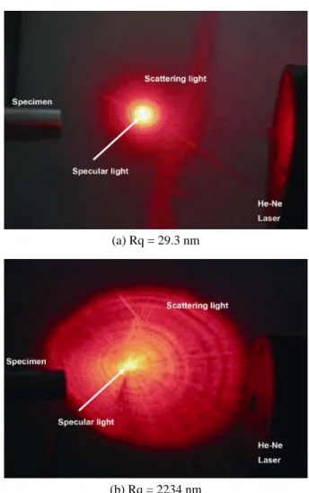
Fig. 2 shows the experimental setup, where the He-Ne laser has an incident angle of 45° to the machined end surface of the aluminum workpiece. Based on the Fres- nel theorem, the incident angle equals the reflective angle when the normal line is perpendicular to the machined end surface of the workpiece. The reflected light with scat- tering effects was collected by the photodiode array. The distance between the workpiece and photodiode was either 26 mm or 50 mm. Fig. 3 reveals the scattering effects induced by the surface roughnesses of 29.3 and 2234 nm, respectively. The light spreads increasingly because of the poor surface roughness of the workpiece made with ultra-precision machining, which mirrors previous litera- ture statements.
III. RESULTS AND DISCUSSIONS With the previous experimental setup with a laser in-
(a) Rq = 29.3 nm
(b) Rq = 2234 nm
Fig. 3 The scattering effects induced by the surface roughnesses of 29.3 and 2234 nm, respectively
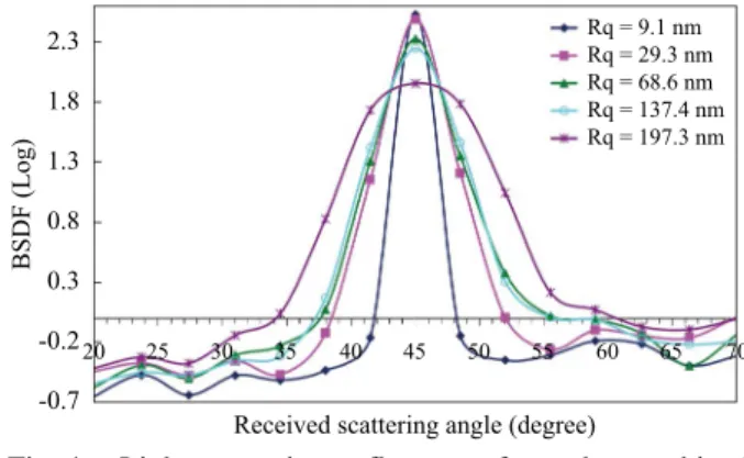
cident angle of 45° and the different levels of the surface roughness, the photodiode array measures the scattering distribution from the end surface of the workpiece at measurement distances of 26 mm and 50 mm. Fig. 4 demonstrates that the received intensity of the specular channel increases as the surface roughness decreases, which is in agreement with results in the previous litera- ture. Moreover, the scattering light has a Gaussian dis- tribution once the surface roughness is smaller. The light scattering distribution increases when the surface rough- ness worsens. The measurement distance shows the same relationship in Fig. 5. Nevertheless, a larger measure- ment distance enhances the BSDF values because of the larger receiving angle of each element of the photodiode array. In other words, for each element of the photodiode, the receiving angle increases with respect to the increased measurement distance.
Because the distribution of the light scattering in-
蔡習訓和馮慧平:以陣列光電二極體量測反射光散射預測超精密加工表面之粗糙度 25
Rq = 9.1 nm Rq = 29.3 nm Rq = 68.6 nm Rq = 137.4 nm Rq = 197.3 nm 2.3
1.8 1.3 0.8 0.3 -0.2 -0.7
BSDF (Log)
20 25 30 35 40 45
Received scattering angle (degree)
50 55 60 65 70
Fig. 4 Light scattering reflectance from the machined aluminum with an incident angle of 45 ° and a measurement distance of 26 mm
Rq = 9.1 nm Rq = 68.6 nm Rq = 137.4 nm Rq = 197.3 nm 3.5
2.5
1.5
0.5
-0.5
BSDF (Log)
20 25 30 35 40 45
Received scattering angle (degree)
50 55 60 65 70
Fig. 5 Light scattering reflectance from the machined aluminum with an incident angle of 45 ° and measurement distance of 50 mm
creases with increased surface roughness, the ratio of re- flective specular light intensity to the sub-channel light intensity of the photodiode array in Fig. 6. The increased ratio means the surface roughness decreases. The ratio of reflective specular light intensity to that behind of sub-channel is clearly related to the surface roughness.
The curve fitting is close to the experimental results sub- ject to the larger value of R
2. Fig. 7, with a measurement distance of 50 mm, has a similar trend to that in Fig. 6. It is confirmed that the received intensity ratio proposed here can be used to predict the surface roughness of the work- piece in an ultra-precision machining process. Little er- ror may be caused by mis-fitting the curve because of fewer experimental databases. To utilize a ready-made prediction database, a further series of experiments should be verified. On the other hand, to improve the prediction approach of the surface roughness measurement system, the easy setup and effective measuring are appropriate for commercial application. The laser and the photodiode
specular/sub-channel specular/behind sub-channel 800
600
400
200
0
Received intensity ratio
0 50 100
Surface roughness Rq (nm)
150 200
y = 12627x-1.6647 R2 = 0.9298 y = 18641x-1.2488
R2 = 0.8274
Fig. 6 Measurement distance 26 mm for the specular/
subchannel ratio versus the surface roughness
specular/sub-channel specular/behind sub-channel 800
600
400
200
0
Received intensity ratio
0 50 100
Surface roughness Rq (nm)
150 200
y = 61916x-2.0198 R2 = 0.8256
y = 45151x-1.7823 R2 = 0.9407
Fig. 7 Measurement distance 50 mm for the specular/
subchannel ratio versus the surface roughness
array predict the roughnesses of the ultra-precision ma- chined surfaces of aluminum well. The on-line meas- urement technique for the roughness using the reflected light scattering effect from the ultra-precision machined surface performed well in this study.
IV. CONCLUSIONS
The received intensity of the specular channel in-
creases as the surface roughness decreases, which is a re-
sult also reported in previous literature. In addition, the
scattering light has a Gaussian distribution once the sur-
face roughness is small enough. This light scattering
distribution gets wider when the surface roughness in-
creases. However, a larger measurement distance en-
hances the BSDF values as a result of a larger receiving
angle for each element of the photodiode array, that is, for
each element of the photodiode, the receiving angle in-
creases as the measurement distance increases. The
BSDF of the machined surface is proportional to rough-
ness. Using the ratio of the main and side measuring
channels of the photo-diode array gives a suitable ap- proach for constructing the relationship between light scattering and surface roughness. Therefore, the laser and the photodiode array predict the roughnesses of the ultra-precision machined aluminum surfaces well.
ACKNOWLEDGEMENTS
Special thanks should be given to the National Sci- ence Council for the financial support under grant NSC 95-2221-E-131-006.
REFERENCES
1. Luk, F., Huynh, V., and North, W., “Measurement of Surface Roughness by a Machine Vision System,”
Journal of Physics E: Scientific Instruments, Vol. 22, No. 12, pp. 977-980 (1989).
2. Bennett, J. M. and Mattson, L., Introduction to Surface Roughness and Scatterin., Optical Society of America, Washington D.C. (1989).
3. Beckmann, P. and Spizzichino, A., The Scattering of Electromagnetic Waves from Rough Surfaces, Artech House Publishers, Norwood, MA, USA (1987).
4. Persson, U., “In-Process Measurement of Surface Roughness Using Light Scattering,” Wear, Vol. 215, No. 1-2, pp. 54-58 (1998).
5. Vandembroucq, D., Tarrats, A., Greffet, J. J., Roux, S., and P louraboué, F., “Light Scattering from Cold Rolled Aluminum Surfaces,” Optics Communications, Vol.
187, No. 4-6, pp. 289-294 (2001).
6. Wang, S. H., Quan, C., Tay, C. J., and Shang, H. M.,
“Surface Roughness Measurement in the Submicro- meter Range Using Laser Scattering,” Optical Engi- neering, Vol. 39, No. 6, pp. 1597-1601 (2000).
7. Tay, C. J., Wang, S. H., Quan, C., Ng, B. L., and Chan, K. C., “Surface Roughness Investigation of Semi-Con- ductor Wafers,” Optics and Laser Technology, Vol. 36, No. 7, pp. 535-539 (2004).
8. Fontani, D., Francini, F., Longobardi, G., and Sansoni, P., “Optical Control of Surface Finish,” Optics and Lasers in Engineering, Vol. 32, No. 5, pp. 459-472 (1999).
9. Fontani, D., Francini, F., Longobardi, G., and Sansoni, P., “Control of Crankshaft Finish by Scattering Tech- nique,” Optics and Lasers in Engineering, Vol. 35, No.
6, pp. 387-396 (2001).
10. Moslehpour, S., Cloutier, G., Shetty, D., and Campana, C., “Determination of Surface Roughness by Laser Light Scatter Using Flexible Microcontroller,” ASME International Mechanical Engineering Congress and Exposition, Seattle, WA, Vol. 13, pp. 115-123 (2008).
11. Li, L., Collins Jr., S. A., and Yi, A. Y., “Optical Effects of Surface Finish by Ultraprecision Single Point Dia- mond Machining,” Journal of Manufacturing Science and Engineering, Transactions of the ASME, Vol. 132, No. 2, pp. 0210021-0210029 (2010).
12. Cahill, B. and El Baradie, M.A., “LED-Based Fi- bre-Optic Sensor for Measurement of Surface Rough- ness,” Journal of Materials Processing Technology, Vol. 119, No. 1-3, pp. 299-306 (2001).
13. Stover, J. C., Optical Scattering: Measurement and Analysis-2nd edition, SPIE Press, Washington, USA, pp. 19-22 (1995).
Manuscript Received: Feb. 11, 2010 First Revision Received: Feb. 22, 2010 Second Revision Received: Jan. 20, 2011 and Accepted: Mar. 01, 2011
![Fig. 1 (a) Incident angle, light scattering angle, and the reflective specular light [Schmitt Measurement Systems, 2004], (b) Incident angle, light scatter-ing angle and the reflective specular light](https://thumb-ap.123doks.com/thumbv2/9libinfo/9129406.413446/3.892.95.427.147.540/incident-scattering-reflective-specular-schmitt-measurement-incident-reflective.webp)