Characterization of coatings on magnetic metal
using the swept-frequency eddy current method
Cheng-Chi Taia)
Department of Electrical Engineering, National Cheng Kung University, Tainan, Taiwan 701, Republic of China
共Received 25 October 1999; accepted for publication 25 April 2000兲
A measurement technique using the swept-frequency eddy current共SFEC兲 method for determining the thickness, conductivity, and permeability of metallic coatings on metal substrates for the case when either coating, substrate, or both are magnetic was developed. This technique involved using the empirically determined permeability of the metals as input to the model calculation. This technique is demonstrated for nickel layers 共25–200 m兲 over copper substrates, copper layers 共25–200 m兲 over nickel substrates, and zinc layers 共50–400 m兲 over steel substrates. The electrical impedance was measured for air-core coils in the presence and absence of the layer using a 4194A Hewlett–Packard impedance analyzer. An analytic closed-form solution for calculating the impedance of a cylindrical air-core probe over a layered metallic half-space is presented. The determination of coating thickness and conductivity and permeability of the metals is based on the comparison of the data taken with air-core coils and theoretical calculation that using the closed-form solution developed. Most of the cases studied show experiment and theory agreeing fairly well, within 10%, with no adjustable parameters. The physical phenomena of eddy currents interaction with the coated magnetic metals are also discussed. © 2000 American Institute of Physics. 关S0034-6748共00兲00508-6兴
I. INTRODUCTION
Coatings and surface treatments find a wide range of technological applications. These treatments can provide wear resistance, oxidation and corrosion protection, electri-cal contact or isolation and thermal insulation. The ability to determine the thickness of metal coatings is important for both process control and in-service part inspection. Presently ultrasonic, thermal, and eddy current inspection methods are used, depending on the circumstances. A number of com-mercial instruments for determining the thickness of noncon-ducting coatings on metal substrates are based on the fact that the impedance change in the coil decreases exponen-tially with the distance of the coil from the metal共the lift-off effect兲. However, these instruments are not suitable for de-termining the thickness of metal layers on conductive sub-strates.
Recently Moulder, Uzal, and Rose1 developed a swept-frequency eddy current technique for determining the thick-ness and the conductivity of a conducting layer over a metal substrate of known conductivity. Their approach was based on an absolute measurement comparison to an exact solution for the impedance of an air-cored coil over a layered metal using the method of Cheng2and Dodd and Deeds.3No cali-bration specimens were either required or used. The ap-proach of Moulder et al. provided good estimates for both the thickness and conductivity. Sethuraman and Rose4 devel-oped a more rapid 共several seconds on the same processor兲 solution that was based on isolating three characteristic fea-tures of the frequency-domain response and then relating the
thickness and conductivity to these features. Tai, Rose and Moulder5developed a transient eddy current method that can determine the thickness and the conductivity of a conducting layer over a metal substrate of known conductivity. A rapid inversion method, based on a look-up table, was developed to determine the thickness and conductivity.
Previous studies were restricted to nonmagnetic metals. In this study, we developed a measurement technique using the swept-frequency eddy current method for determining the thickness, conductivity, and permeability of metallic coatings on metal substrates for the case when either the coating, substrate, or both are magnetic. This method in-volves using the empirically determined permeability of the material as input to the model calculation. We demonstrated this technique for copper layers over nickel substrates, nickel layers over copper substrates, and zinc layers over steel sub-strates.
The organization of this paper is as follows. In Sec. II, we review and develop the theory needed to describe frequency-domain impedance for the swept-frequency eddy current method. Next we describe the experimental setup and measurements in Sec. III. Results are described and theory and experiment are compared in Sec. IV. Discussions and conclusions are also presented in this section.
II. THEORY
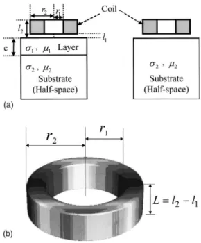
Figure 1共a兲 shows a schematic diagram of the model under study. The conductivity and permeability of the layer is denoted by1 and1, and that of the substrate by2and 2. The thickness of the layer is denoted by c. The base of the coil is at a height l1 above the surface and the top of the
a兲Electronic mail: [email protected]
3161
coil is at z⫽l2. The important coil parameters are the num-ber of turns N, inner and outer radii r1 and r2, and coil height L⫽l2⫺l1. See Table I and Fig. 1共b兲 for the param-eters and geometry of the coils used in this study.
Cheng, Dodd and Deeds6 provided analytical solutions for coils near stratified conductors. We present these
solu-a thick substrsolu-ate plsolu-ate, where the thickness of the plsolu-ate is always many times greater than the skin depth. In the theo-retical calculations we approximated the thick plate as a semi-infinite half-space. The coil impedance above a mag-netic, single-layered half-space is determined using
ZL⫽K j
冕
0 ⬁P2共r2,r1兲 ␣5再
2L⫹ 1 ␣关2 exp共⫺␣L兲⫺2 ⫹A共␣兲共␣兲兴冎
d␣, 共1兲 where K⫽ 0N 2 共l2⫺l1兲2共r2⫺r1兲2 , 共2兲 P共r1,r2兲⫽冕
␣r1 ␣r2 xJ1共x兲dx, 共3兲 A共␣兲⫽关exp共⫺␣l2兲⫺exp共⫺␣l1兲兴2, 共4兲 共␣兲⫽共␣1⫹␣10兲共␣12⫺␣21兲⫹共␣1⫺␣10兲共␣12⫹␣21兲exp共2␣1c兲 共␣1⫺␣10兲共␣12⫺␣21兲⫹共␣1⫹␣10兲共␣12⫹␣21兲exp共2␣1c兲 , 共5兲 and ␣i⫽冑
␣ 2⫹ j ii. 共6兲In the above expressions, J1is a Bessel function of first kind and first order, 0 is the permeability of free space, and denotes the angular frequency.
The coil impedance above a reference half-space is de-termined using ZHS P⫽K j
冕
0 ⬁P2共r2,r1兲 ␣5再
2L⫹ 1 ␣冋
2 exp共⫺␣L兲⫺2 ⫹A共␣兲␣2⫺␣20 ␣2⫹␣20册冎
d␣. 共7兲We measured the coil impedance for a coil above a single layered half-space and the half-space of the base material. The impedance difference, ⌬Z, for these two cases is re-ported, ⌬Z⫽K j
冕
0 ⬁P2共r2,r1兲 ␣6 A共␣兲冉
共␣兲⫺ ␣2⫺␣20 ␣2⫹␣20冊
d␣. 共8兲 III. EXPERIMENTAL SETUP AND MEASUREMENTSThe frequency-dependent impedance change induced in a small air-core coil placed next to the sample’s surface was inferred by measuring the impedance change with a 4194A Hewlett–Packard impedance analyzer. Measurements were made at 400 equally spaced frequencies in the range from 1 kHz to 1 MHz. The measurement process and the coil are shown schematically in Figs. 1共a兲 and 1共b兲. The impedance of the coil was measured above a half-space first, to obtain a value ZHS P() at each frequency. The coil was placed on the single layered metal surface next and the impedance ZL() was measured again over the same frequency range. The uncorrected impedance change ⌬Z()⫽ZL()⫺ZHS P() was then calculated. Measurements were made and recorded using an eddy current workstation, shown schematically in
FIG. 1. 共a兲 Schematic representation of the model. The impedance of the coil above the layered material was subtracted from the impedance mea-sured with the coil above the substrate not covered by the layer.共b兲 Geom-etry of the air-core coil used in the experiments.
Fig. 2. This workstation consisted of a personal computer that controls the impedance analyzer and a fixture that holds the coil in firm contact with the sample.
Two precision-wound and nearly right cylindrical coils were used as probes. The coil measurement parameters are given in Table I. The coil resistance will be canceled when the impedance difference is calculated. This value is crucial for calculating the current difference in the time domain, since the admittance difference, ⌬Y, is used in this case. At sufficiently high frequencies the effects of stray capacitance become significant, and the measurement circuit resonates.
The measured impedance changes will be compared with the theory of Cheng, Dodd and Deeds,6which idealizes the measurement system by assuming that the coil capaci-tance is zero. For a broad range of frequencies, this is a reasonable approximation. However, we found that the data were slightly altered 共on the order of 10%兲 by the capaci-tance 共and the resulting resonance兲 for the highest frequen-cies measured. At high frequenfrequen-cies, the current is coupled capacitively between the turns in the coil, tending to flow across the loops of the wire, rather than through them. In practice, any real coil exhibits self-capacitance and resistance as well as additional capacitance associated with the leads. These deviations from ideal behavior must be taken into ac-count if good agreement between theory and experiment is to be obtained at high frequencies. Consequently, we corrected the impedance changes for the effects of stray capacitance by following a procedure recently introduced by Harrison et al.7 Harrison et al. introduced the equivalent electrical cir-cuit, shown in Fig. 3, to model the coil’s behavior. Here, R0 and L0 are the direct current 共dc兲 resistance and inductance of the coil, respectively. ZCis the reflected impedance due to eddy current induction in any neighboring conductors. RS
and CSrepresent the resistance and self-capacitance, and CL represents the lead capacitance. The unspecified network, RC, represents all other behavior. All of these elements were lumped together for convenience into a single parallel net-work ZP. The presence of the parallel circuit, ZP, results in deviations in the coil’s impedance from the zero-capacitance value by an amount that increases with frequency and ulti-mately leads to coil resonance at a resonant frequency fR.
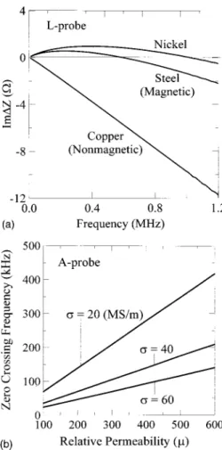
The approach of Harrison et al. uses the equivalent cir-cuit to estimate how much the signal has been altered by the capacitance effects, and then subtracts this change from the FIG. 4.共a兲 Impedance differences for a coil above the metal and the coil in air.共b兲 The zero-crossing frequency is a function of the permeability and conductivity.
FIG. 5. Determining the permeability of a metal共steel block, by A-probe兲.
FIG. 2. Block diagram of the swept-frequency eddy current instrument used in this work.
capacitance theory of Cheng, Dodd and Deeds. The imped-ance data were corrected in the following way. The coil im-pedance ZA was measured in air over the selected frequency range. The dc resistance and inductance values, R0 and L0, were determined from the low-frequency limit and used to calculate the ideal admittance,
Y0共兲⫽1/共R0⫹ jL0兲. 共9兲
This was subtracted from the admittance in air (YA) to give the admittance of the equivalent parallel network, YP⫽YA ⫺Y0. Next, we estimated the reference signal as follows. First, the impedance ZU was measured over an unflawed region of the test specimen. Second, the ideal admittance of the parallel circuit was subtracted from the admittance YU (⫽1/ZU) to give the corrected impedance ZcorrU ⫽1/(YU ⫺YP) .
The corrected impedance change for the reference sample was obtained from
⌬Zcorr U ⫽Z
corr U ⫺Z
0. 共10兲
The impedance difference due to the presence of a defect, flaw, or any change in the sample was corrected using the same logic. We used
⌬Zcorr D ⫽ 1 YD⫺YP ⫺ 1 YU⫺YP , 共11兲
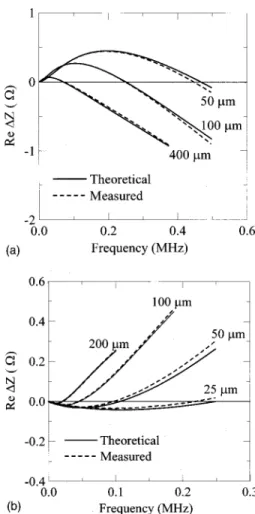
where YDis the admittance measured in the presence of the defect. The effect is to substantially cancel out the effects of stray capacitance and the resulting resonance. All measure-ments reported in this paper are for the corrected quantities. The method we used to determine the permeability of metals was based on comparing the theoretical estimations to the practical measurements using the swept-frequency eddy current method. This arises from the complexities of the in-teraction between the coil impedance and magnetic metals. If the material is conducting and magnetic 共i.e., ⬎0,r⬎1) 共such as nickel, iron, steel and cobalt兲, the exciting coil’s reactance changes in a different way than with nonmagnetic test materials. The flux lines within the magnetic material find portions of their path in such material to have far less reluctance than air. This means that the path of the flux lines is shortened and then the magnetic flux density in the coil is increased. The coil inductance and inductive reac-tance increase dramatically when a highly permeable mag-netic material is tested. However, if the frequency of the alternating current共ac兲 is high enough, the influence of eddy FIG. 6. Comparison of theory and experiment for swept-frequency eddy current measurements.共a兲 Nonmagnetic coatings on magnetic base metal.
共b兲 Magnetic coatings on nonmagnetic base metal.
TABLE III. Actual thickness and estimated thickness from the comparison of measured and calculated data.
Layer Substrate Thickness共m兲 Actual Inferred Zn Steel 50⫾1 49–54 100⫾1 103–109 150⫾2 147–160 201⫾2 202–207 251⫾2 247–263 300⫾3 292–326 349⫾3 351–378 402⫾5 396–437 Ni Cu 25⫾1 23–27 51⫾1 47–55 75⫾1 72–82 102⫾1 99–108 127⫾1 124–135 152⫾2 148–165 177⫾2 173–187 203⫾3 198–228 Cu Ni 25⫾1 24–28 50⫾1 46–56 76⫾1 73–82 101⫾1 95–106 126⫾2 123–133 151⫾2 146–163 176⫾3 171–189 202⫾4 195–224
currents becomes predominant. The net effect is to decrease the inductance with increasing frequency. A zero crossing occurs when these two effects are in balance 关Fig. 4共a兲兴 共measurements were taken first with the probe in air, then with the probe in firm contact with the sample. The imped-ance difference is reported兲, and it provides a sensitive mea-sure of the ratio / 关Fig. 4共b兲兴. If the conductivity is known, it accurately predicts the permeability for the uni-form half-space model and single layer in air. Figure 5 shows the calculations of the change in the coil impedance when going from metal 共steel兲 to air compared to the measured values. The theoretical calculations are for different values of initial permeability. The frequency at which the impedance crosses zero is proportional to the initial permeability.
Table II contains the electrical conductivities and perme-abilities of the layers and substrates we used. The conduc-tivities were empirically determined and permeabilities were fitted from the swept-frequency measurements. Note that the permeability of the nickel layer and substrate have different values. This is because the nickel layers are rolled foils. The stress induced during the manufacturing will dramatically change the permeability.
Measurements were taken for a variety of samples, in-cluding layers of zinc, copper and nickel over steel, nickel, and copper substrates. Eight foil samples of pure nickel were prepared by stacking to different thickness ranging from 25 to 200m. Copper foils of thickness ranging from 25 to 200 m were prepared in a similar fashion using copper 101.
Eight zinc foils were used ranging from 50 to 400m. For most of the measurements we report here, these foils were placed in contact with a given substrate and the probe was then placed upon the foil.
IV. RESULTS AND DISCUSSION
The coating thickness estimated from the experimental data is reported in this section. Three combinations of foil and substrate metals were studied: zinc, nickel, and copper foils over steel, copper, and nickel substrates. For most of the cases studied, experiment and theory agree fairly well, within 10%共see Table III兲, with no adjustable parameters.
Some selected measurements were compared with the theoretical calculations. Figure 6共a兲 shows the case for non-magnetic coatings on non-magnetic base metals using the SFEC method. The L-probe was used in these measurements. We compared theory and experiment for frequency-domain eddy current measurements of zinc foils of different thickness 共50–400m兲 on a steel alloy substrate. The real parts of the impedance change indicate good agreement between theory and experiment for the specimens measured. Over the range of frequency for which ⌬Z was measured, the maximum disagreement was about 10%. Figure 6共b兲 shows the case for magnetic coatings on nonmagnetic base metals 共nickel foils on copper substrate兲 using the same EC method. The maxi-mum disagreement in this case was about 14%.
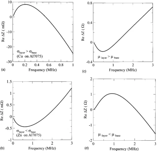
FIG. 7. The effects of conductivity and permeability on the impedance change. 共a兲 layer⬎base, 共b兲 layer
⬍base, 共c兲 layer⬎base, 共d兲 layer
共1兲 the effect of conductivity, and 共2兲 the effect of permeability. If we assume that the layer and the substrate have identical permeability, then the situation is the same as the nonmagnetic materials case discussed in the work of Moulder et al.1 The impedance change trend de-pends on the conductivity of the layer and the substrate. If the layer has a higher conductivity than the substrate 共e.g., Cu on Al7075兲, the signal will start from zero and reach the positive maximum, then return to the negative. A zero occurs for some intermediate frequencies as shown in Fig. 7共a兲.
Figure 7共b兲 shows the inverse situation of 7共a兲, a lower conductivity layer on a higher conductivity substrate共i.e., Zn on Al7075兲. The signal will start from zero and reach the negative maximum, then return to the positive. A zero occurs between the low- and high-frequency limits.
If we assume that the layer and the substrate have iden-tical conductivity, as has been discussed in Sec. III, the per-meability will increase the magnetic flux in the metals. The net effect on the impedance change then depends on both the permeability and eddy currents, since the distribution of eddy currents in the metals is a function of the frequency. We examine and discuss the impedance change based on pos-sible combinations of permeability in frequency domain. As shown in Fig. 7共c兲, a higher permeability layer (r⫽320) on a lower permeability substrate (r⫽180). Here we assume that the metals are nickel, with same conductivity (14.6 ⫻106 S/m兲 but different permeability. The signal (⌬R) starts from zero and reaches the negative maximum, then returns to the positive. This curve is actually opposite to the conductivity effect as shown in Fig. 7共a兲. Figure 7共d兲 shows the situation inverse to Fig. 7共c兲, a lower permeability layer (r⫽180) on a higher permeability substrate (r⫽320). Again, this curve is opposite to the conductivity effect as shown in Fig. 7共b兲 and it is also opposite to Fig. 7共c兲.
If we take an overview of the signals in Figs. 6 and 7, as in the nonmagnetic cases, when the coating thickness ap-proaches zero, the zero-crossing frequency will become infi-nite. In other words, a thicker coating has a lower zero-crossing frequency. This phenomenon can be explained from the point of view of energy dissipation discussed above. The power dissipates in the layered sample and the reference sub-strate balances at a higher frequency for thinner coating. So the zero crossing shifts to higher frequency when the coating becomes thinner. Based on the characteristics of the signals, we can find that the features in these signals are the peak-height 共a characteristic relative maximum兲, the peak-frequency共frequency that peak-height occurs兲, and the
zero-crossing frequency. We can examine the coating based on these features.
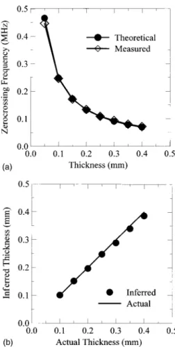
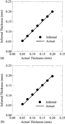
Figure 8 shows the coating thickness estimation using the SFEC method. We assumed that the conductivities of the metals are known and that the permeability of the steel was measured in a separate experiment. Figure 8共a兲 compares the calculated and measured zero-crossing frequency for a series of zinc foils of varying thickness on a steel substrate. Figure 8共b兲 shows the inferred thickness of zinc foils compared to actual thickness. Thickness was determined from the zero-crossing frequency in the real part of impedance change be-tween a specimen with a layer and the substrate alone using the theoretical prediction of the relationship between the zero-crossing frequency and thickness. No calibration or fit-ting factors were used. Two more examples that show the coating characterization using the same method are shown in Fig. 9 for nickel foils on a copper base and copper foils on a nickel base. As shown, the inferred thickness is very close to the actual thickness for both cases. Table III summarizes the actual thickness and estimated thickness from the compari-son of measured and calculated data for the three cases.
As evidenced from the results, we have developed a measurement technique for determining the thickness, con-ductivity and permeability of metallic coatings on metal sub-strates for the case when the coating, metal, or both are mag-netic. When using this technique to examine the thickness or conductivity of the coatings, we must know the permeability FIG. 8.共a兲 Comparison of calculated and measured zero-crossing frequency in the real part of the impedance change for a series of zinc foils on a steel substrate.共b兲 Inferred thickness of zinc foils compared to actual thickness.
of the metals a priori. If the conductivity of the base metal is known, then we may use the feature-based inversion meth-ods developed by Moulder1to simultaneously infer the thick-ness and conductivity of the coating. However, we showed in this work that it is relatively easy to infer the layer thickness if its conductivity is known and vice versa. One challenge
that must be conquered is to determine the thickness, con-ductivity, and permeability of the coating simultaneously. One must find more features in the SFEC signals that can be used to infer these three unknown parameters at the same time.
The technique we developed can be quite accurate and is sensitive to very thin coatings, on the order of several mi-crons. In our other works,8–10we discovered that the broad-band behavior of eddy current coils in proximity to ferro-magnetic surfaces 共nickel and iron兲 depends dramatically upon very thin surface layers. For nickel, we found a ⬃20 m thick oxidized layer at the surface that reduced the ap-parent relative magnetic permeability substantially. Con-versely, this extreme sensitivity to surface conditions means that measurement methods can be devised that will be sen-sitive to very thin surface coatings, on the order of a few microns thick or less. This work paves the way for develop-ing a new, quantitative method to characterize surface layers on ferrous materials, such as depth of case hardening. ACKNOWLEDGMENTS
This work was supported by the National Science Coun-cil, Taiwan, R.O.C., under Contract No. NSC 89-2213-E-006-092.
1J. C. Moulder, E. Uzal, and J. H. Rose, Rev. Sci. Instrum. 63, 3455
共1992兲.
2D. H. S. Cheng, IEEE Trans. Instrum. Meas. IM-14, 107共1965兲. 3
C. V. Dodd and W. E. Deeds, J. Appl. Phys. 39, 2829共1968兲. 4A. Sethuraman and J. H. Rose, J. Nondestruct. Eval. 14, 39共1995兲. 5C.-C. Tai, J. H. Rose, and J. C. Moulder, Rev. Sci. Instrum. 67, 3965
共1996兲.
6
C. C. Cheng, C. F. Dodd, and W. E. Deeds, J. Nondestruct. Test 3, 109
共1971兲.
7D. H. Harrison, L. D. Jones, and S. K. Burke, J. Nondestruct. Eval. 15, 21
共1996兲.
8J. H. Rose, C.-C. Tai, and J. C. Moulder, in Review of Progress in QNDE, edited by D. O. Thompson and D. E. Chimenti 共Plenum, New York, 1997兲, Vol. 16, p. 249.
9J. H. Rose, C.-C. Tai, and J. C. Moulder, J. Appl. Phys. 82, 4604共1997兲. 10J. C. Moulder, C.-C. Tai, B. Larson, and J. H. Rose, IEEE Trans. Magn.
34, 505共1998兲. FIG. 9. 共a兲 Inferred thickness of nickel foils on copper substrate compared
to actual thickness.共b兲 Inferred thickness of copper foils on nickel substrate compared to actual thickness.