Chi-Chou Kao
National Pingtung Institute of Commerce Department of Information Technology 51 Min-Sheng E. Road
Pingtung, Taiwan
E-mail: [email protected]
Chuen-Yau Chen
National Yunlin University of Science and Technology
Department of Electrical Engineering University Road, Section 3
Yunlin, Taiwan
E-mail: [email protected]
Yen-Tai Lai
National Cheng Kung University Department of Electrical Engineering No. 1, Ta-Hsueh Road
Tainan, Taiwan
E-mail: [email protected]
Abstract. An efficient moving-object segmentation algorithm suitable for implementing on a chip is proposed. The basic idea is to use simulta- neously a novel spatial segmentation algorithm and an effective tempo- ral algorithm based on the accumulative information technique to pro- duce the video objects. First, the spatial and the temporal segmentation algorithms are used simultaneously to produce the edges and the region of a moving object, respectively. Then, we make use of the edges with the region to obtain the object. It is found that the number of time- consuming motion estimation computations can be reduced dramatically.
Hence, the overall processing speed is significantly accelerated to meet the hardware implementation requirement. Finally, a postprocessing step is applied to the object to smooth the object boundary. Good perfor- mance of this algorithm is demonstrated by experimental results.
© 2006 Society of Photo-Optical Instrumentation Engineers. 关DOI: 10.1117/1.2203369兴Subject terms: multimedia; motion detection; image segmentation
.
Paper 050250RR received Apr. 2, 2005; revised manuscript received Sep. 12, 2005; accepted for publication Sep. 13, 2005; published online May 10, 2006.
1 Introduction
In the past, the video standards, such as MPEG-1 and MPEG-2, used frame-based coding algorithms in various multimedia applications. However, they did not have good flexibility in access and manipulation of objects. To provide efficient coding performance, the MPEG-4 multimedia communication standard
1,2enables content-based function- alities by using the video object plane 共VOP兲, which in- cludes the shape and texture information of a semantically meaningful object in the scene as the basic coding element.
Using such functionality, plain video sequences can be de- composed into several objects for recomposing with other objects or be transmitted through a network separately to increase the efficiency of bandwidth usage.
Segmentation can be defined as the operation of parti- tioning a scene into regions extracted according to a given criterion. Image segmentations have included extraction of features such as edges and curves and integration of these features into continuous shapes that are spatially coherent.
3–8Video segmentations, in addition to those tech- niques used for image segmentation, have included tempo- ral change detection due to motion of individual objects in a temporally coherent manner. Hence, an efficient segmen- tation algorithm is more necessary in video than in image processing. Moreover, many multimedia application sys- tems have been implemented on chips to achieve high- speed processing for video segmentation.
According to the given segmentation criteria, conven- tional segmentation algorithms can be divided into two cat- egories: 共1兲 spatial segmentation algorithms, whose criteria
are spatial homogeneity, and 共2兲 temporal segmentation al- gorithms, whose criteria are change detection. A spatial segmentation algorithm
9–11consists of three steps. In the first step, morphological filters are used for image simpli- fication. The second step approximates the spatial gradient by a morphological gradient operator, which is also treated as an input to a watershed algorithm for identifying the regions with homogeneous intensity. The third step merges the regions, usually oversegmented, in the watershed algo- rithm. The algorithms focus on finding more precise object boundaries. However, because both the watershed algo- rithm and the region merging are computation-intensive op- erations, the computational complexity is very high. For temporal segmentation, the algorithms
12–15consist of two steps. The first step consists in estimating a change detec- tion mask; the second step consists in generating an object mask by eliminating the uncovered background from the change detection mask in the first step.
We believe that the temporal segmentation algorithms are more efficient than the spatial segmentation algorithms because they distinguish a moving object from the back- ground. However, the quality of the segmentation will not be satisfactory if the speed of the object changes signifi- cantly in the sequence. Moreover, the motion estimation is a time-consuming operation, and the whole processing speed is significantly decreased in turn.
In this paper, we propose spatiotemporal algorithms to design an efficient segmentation system that is suitable for implementing on a chip and for any object motion. Good performance of the proposed algorithms is demonstrated by the simulation results. The rest of this paper is organized as follows. An overview of the proposed system used to ex-
0091-3286/2006/$22.00 © 2006 SPIE
tract the moving objects is given in Sec. 2. Section 3 de- scribes in detail the spatiotemporal segmentation algo- rithms. The experimental results are shown in Sec. 4.
Finally, Sec. 5 gives conclusions.
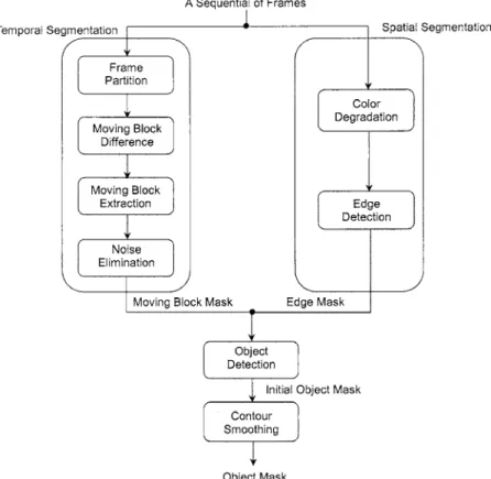
2 The System Overview
The basic idea of the proposed system is to use simulta- neously the spatial and the temporal segmentation algo- rithms based on the accumulative information technique to produce the expected segmentation masks. In contrast with other segmentation systems,
9–15our judgment criterion for motion is not based on the difference between two adjacent frames. Instead, we process a sequence of frames to com- pute the differences among the successive frames.
Using two consecutive frames to establish a correspon- dence of moving objects between frames is the most com- mon method. However, the resulting motion estimations are not accurate if the object moves on a noiseless or self- colored background. It is obvious that the more the moving frames there are, the larger is the difference between the moving object and the background. Moreover, in general,
noise cannot remain in the same position for a sequence of moving frames, so that any pixel that changes significantly from frame to frame can be treated as noise and removed from the object region. Therefore, we strongly believe that processing a sequence of frames can produce more accurate segmentation masks than processing just two consecutive frames. Figure 1 illustrates the effect of computation with different numbers of frames on the performance of the pro- posed system.
The proposed system is divided into four main steps—
temporal segmentation, spatial segmentation, object detec- tion, and contour smoothing—as shown in Fig. 2. The spa- tial segmentation and the temporal algorithms are first used in parallel to produce the edge tracks called the edge masks and the moving object regions called the moving block masks, respectively. Next, we combine these masks to ob- tain the initial object masks. Accordingly, the number of time-consuming motion estimations can be reduced, and the whole processing speed is significantly accelerated in turn. Hence, although we process more frames in this sys- tem than in other systems,
9–15good object masks can still
Fig. 1 The effect on the computation of using sequences of共a兲 two frames, 共b兲 six frames, 共c兲 eleven frames, and共d兲 twenty-six frames.
Fig. 2 Diagram of the proposed video segmentation system.
be acquired without increasing the computational complex- ity. Such a system is suitable for implementing on a chip.
Finally, in the contour-smoothing step, the initial object mask is postprocessed to remove small residual background regions so that the final object masks are good.
3 A Spatiotemporal Segmentation Algorithm Recall that the proposed system is divided into four main steps: temporal segmentation, spatial segmentation, object detection, and contour smoothing. In this section, we de- scribe in detail the segmentation algorithms of those steps.
3.1 Temporal Segmentation Step
The objective of the temporal segmentation step is to ana- lyze the motion relationships among the given video se- quence frames and generate the moving block masks. For this purpose, we use an unsupervised segmentation method in which human assistance is unnecessary. In this method, because the initial moving block masks approximate to the final moving block masks, the number of motion estima- tions can be greatly reduced. It is suitable for implementing the whole system in hardware.
9Figure 3 illustrates an un- supervised segmentation scheme.
When we compute the difference of blocks to find the moving block masks, a large block size is chosen that will cause small noise flutters in luminosity in the selected mov- ing block mask. Moreover, the signal-to-noise ratio will be too small to distinguish the objects from the background.
However, although using small block size efficiently re- moves most of the random noises, it will need a large num- ber of computations. According to the experimental results shown in Fig. 4, a 4 ⫻4 block size is the best choice for a
64⫻64 frame. In other words, if the block size is selected as 1/16 of the original frame size, the proposed system achieves the best video quality.
The accumulative information technique is used to ex- tract the moving block masks. Let n be a suitable number of frames that are processed in sequence to find the moving block masks. Let T
1and T
2denote the threshold values for determining whether a block belongs to the moving block mask or the background. Note that n , T
1, and T
2are treated as the inputs of the chip and can be dynamically adjusted by designers to improve the video quality. We compare every frame with the first frame. If the difference D
k共i, j兲 of the block at the same position 共i, j兲 between the first frame f
1共i, j兲 and the k’th frame f
k共i, j兲 is more than T
1, the block value B
k共i, j兲 is accumulated into the corresponding memory M共i, j兲, where 2ⱕkⱕn. After all frames are pro- cessed, if M共i, j兲 is more than T
2, the corresponding block is selected to be part of the moving block mask, MB 共i, j兲.
The procedures can be described by the following equa- tions:
D
k共i, j兲 =
兺i=1
4 兺
j=1 4
兩f
1共i, j兲 − f
k共i, j兲兩, 2 ⱕ k ⱕ n, 共1兲
Fig. 5 Generation of the moving block masks:共a兲 the initial moving block masks,共b兲 effect of noise-region elimination, and 共c兲 the final moving block masks.
Fig. 6 Noise removal:共a兲 basic block element expression and 共b兲 scan procedure.
Fig. 3 The unsupervised video segmentation scheme.
Fig. 4 Block size comparison:共a兲 2⫻2 block size, 共b兲 4⫻4 block size, and共c兲 8⫻8 block size.
B
k共i, j兲 = 冦 1 if D 0 otherwise,
k共i, j兲 ⬎ T
1, 2 ⱕ k ⱕ n, 冧 共2兲
M共i, j兲 =
兺k=2 n
B
k共i, j兲, 2 ⱕ k ⱕ n, 共3兲
MB 共i, j兲 =
再1 if M 0 otherwise. 共i, j兲 ⬎ T
2,
冎共4兲
After extracting the initial moving block masks as shown in Fig. 5共a兲, there is still some tiny noise due to the camera noise or irregular object motion. To refine the qual-
ity of the moving block masks, we need a method to elimi- nate noise. The traditional method is to use morphological filtering operations.
3However, the need to structure the el- ement shape and size will lead to a high time complexity.
A 3⫻3 block matrix is called a basic block element if we have found the largest value in the matrix and filled it into all the nonzero blocks of the matrix. Figure 6共a兲 shows a diagram of a basic block element. We select the first nine blocks in the initial moving block as the first 3 ⫻3 block.
Let the blocks in the third row of the preceding 3 ⫻3 block be the blocks in the first row of the next 3 ⫻3 block. Ac- cordingly, we set all 3⫻3 blocks for every fourth column in the initial moving block as shown in Fig. 6共b兲. Next, the first cycle is performed to set all 3 ⫻3 block matrices as the basic block elements by scanning the initial moving block from top to bottom and row by row. When the first cycle is
Fig. 7 The full directional Laplacian edge operator.
Fig. 8 Histograms of a frame of the video sequence “Akiyo”:共a兲 original histogram, 共b兲 5 bits shifted, 共c兲 6 bits shifted, and 共d兲 7 bits shifted.
Fig. 9 The edge masks共a兲 using the traditional Laplacian operator, and共b兲 using the proposed spatial segmentation algorithm.
finished, the local maximal value is propagated downward.
Finally, the blocks located in the middle of the central blocks of the existing 3 ⫻3 blocks are selected as the cen- tral blocks of another set of 3 ⫻3 blocks. We perform the second cycle by scanning from bottom to top to distribute the largest value to other connected points, as shown in Fig.
6共b兲.
The pixel densities of the regions that have large noise are much less than the pixel densities of the other regions in the initial moving block. For example, in Fig. 5 共a兲, the pixel density of region A is less than that of region B. After scanning, there is a cluster of pixels that has a larger den- sity than elsewhere. Generally, the speckles form small groups whose values are less than 50. Therefore, we set blocks whose values are smaller than 50 to zero and the others to one for the final moving block. Figure 5共b兲 shows the effect of noise-region elimination on Fig. 5共a兲, and the final moving block masks are shown in Fig. 5共c兲.
3.2 Spatial Segmentation Step
In this subsection, an efficient spatial segmentation algo- rithm including color degradation and Laplacian operator steps is proposed to generate the edge masks.
The common edge-detection technique is the computa- tion of a local derivative operator such as the Laplacian
operator,
16which is a second derivative. However, the La- placian operator is time-consuming because of problems in edge direction detection such as noise sensitivity and double edge generation.
16To reduce the computational complexity, we execute a color degradation step in which every pixel is quantized by shifting pixel intensity bits. The Laplacian operator is improved by detecting full direction changes to solve the edge direction problem. Figure 7 shows the full directional Laplacian edge operator. The method not only detects edges reliably but also simplifies the computation procedures so that it is suitable for hard- ware implementation.
Figure 8共a兲 is the original histogram of a frame of the video “Akiyo.” Although it contains a wide spread of val- ues, as would be expected, the computation complexity will be large for detecting edges. Obviously, the more shifted bits there are, the smaller the number of regions and the computation complexity are. However, if the number of shifted bits is too large, the resolution is reduced so that the quality of the images is not good. According to experimen- tal results on many video frames, shifting 4 to 5 bits is the best choice. Figure 8共b兲 and 8共d兲 illustrate the selection of the number of shifted pixel intensity bits.
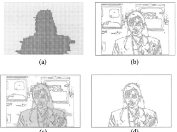
Figure 9共b兲 shows the edge masks generated by the pro- posed spatial segmentation algorithm. By comparison with the edge masks produced by using only the traditional La- placian operator as shown Fig. 9共a兲, it is seen that the pro- posed method is superior to the traditional one.
3.3 Object Detection Step
An object mask is the bound on the variation of every frame within a short period. We find the conjunction edge masks by mapping the moving block masks to the edge masks for every frame to produce the object masks. Figure
Fig. 10 Generation of the initial object masks: 共a兲 moving block masks,共b兲 edge masks, 共c兲 mapping moving block masks to edge masks, and共d兲 initial object masks.
Fig. 11 Spur judgment.
Fig. 12 Traditional interpolation method.
Fig. 13 Form of the interpolation approximation line.
10 illustrates the procedure. It is obvious that the boundary of the object masks is very rough. We present a method to smooth the contours in the next subsection.
3.4 Contour-Smoothing Step
In this step, spurs are removed from a mask. To improve the quality, we calibrate line segments with multiple refer- ence values and execute depth and breadth simultaneously.
The contour curves of a mask are divided into four: the left, right, upper, and lower. For each contour curve, if the distance from a nonspur point to any point x is less than a default value, then x is viewed as a nonspur point. Other- wise, we use the interpolation method to judge whether a point is a spur or not. If any point is located out of the interpolation regions that is computed from existing non- spur points, that point is viewed as a spur.
Figure 11 illustrates the procedure. Suppose the points in region A are nonspur points and the distances from region A to region B and from region B to region D are less than the default value. Hence, all points in B and D are viewed as nonspur points. The region C needs to be further judged by using the interpolation method. In this step, the interpo- lation method is the main determinative factor that is used to judge whether a point is a spur or not. Hence, the default value is set generally as the distance from the center of the object mask to its nearest boundary point.
The traditional interpolation method, as shown in Fig.
12, needs division and precision operations, which are not suitable for hardware implementation. To overcome this problem, we propose a method in which values do not need to be converted to floating-point numbers.
Let 共x
head, y
head兲 and 共x
tail, y
tail兲 be the locations of two known nonspur points. If 共x
head, y
head兲 and 共x
tail, y
tail兲 are both odd or both even, a new nonspur location can be lo- cated by shifting to 共x
head+ x
tail, y
head+ y
tail兲; otherwise, it is
located by shifting to 共x
head+ x
tail+ 1 , y
head+ y
tail兲. This step is executed recursively by changing 共x
head, y
head兲 and 共x
tail, y
tail兲 until interpolation lines are found. Any point that is located out of the interpolation region is viewed as a spur. For example, in Fig. 13, 共x
3, y
3兲 can be determined according to 共x
1, y
1兲 and 共x
2, y
2兲, which are the initial known nonspur locations. The new nonspur locations, 共x
4, y
4兲 and 共x
5, y
5兲, can be found respectively by comput- ing the pairs of nonspur locations 共x
1, y
1兲共x
3, y
3兲 and 共x
3, y
3兲共x
2, y
2兲. The nonspur locations form an interpolation region to judge whether a point is a spur or not.
The effect of contour smoothing is shown in Fig. 14. It can be seen that spurs are removed as required but that part of the region that is not required to be deleted has been.
However, the algorithm removes spurs on convex objects.
For an initial object mask, we execute depth and breadth contour smoothing simultaneously to generate the final ob- ject mask. Figure 15 illustrates the procedure. Using the final object mask, the video object plane 共VOP兲 can be extracted as shown in Fig. 16.
4 Experimental Results
We have simulated the proposed algorithm on the standard MPEG-4 test sequences to evaluate its objective qualities.
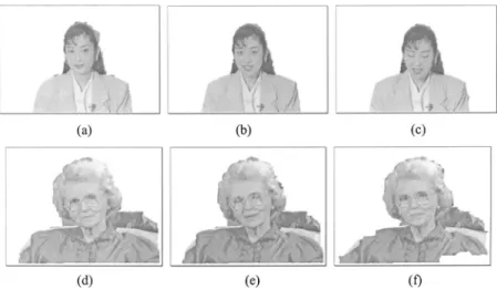
Figure 17 shows the segmentation results for several bench- mark sequences taken from “Akiyo” and “Grandma.” The
“Akiyo” sequences do not have background noise, so their segmentation results are better than those of “Grandma.” In the “Grandma” sequences, shadows of the sofa appear in the background region. Compared with the previous results,
14,15our segmentation results are quite good. Fast-
Fig. 14 Effect of contour smoothing: 共a兲 original frame and 共b兲
contour-smoothed frame. Fig. 15 Generation of the final object masks: 共a兲 initial object
masks, 共b兲 original breadth object masks, 共c兲 contour-smoothed breadth object masks,共d兲 original depth object masks, 共e兲 contour- smoothed depth object masks, and共f兲 final object masks.
Fig. 16 Video object plane extraction:共a兲 final object masks, 共b兲 original frame, 共c兲 video object plane.
moving or low-resolution benchmark sequences are more difficult to segment because the resolution of this specimen becomes low, so that several background pixels are mixed with foreground objects. However, the moving objects can still be extracted by our method, as shown in Fig. 18.
We use a personal computer with a Pentium-III 800-MHz processor as the test platform to implement the proposed algorithm, shadow cancellation 共SC兲 mode, and global motion compensation 共GMC兲 mode.
16The test se- quences are in QCIF format. In this work, a processing speed of 30 QCIF frames per second, meeting the real-time requirement, can be achieved. However, the processing speed is slowed down to 21 QCIF frames per second in SC mode. In GMC mode, the processing speed is 10 QCIF frames per second. These experimental results reveal that the proposed algorithm is suitable for chip implementation.
5 Conclusions
In this paper, we have proposed an algorithm making use of accumulative information of multiple frames for moving- object segmentation. It is divided into four main steps: tem- poral segmentation, spatial segmentation, object detection, and contour smoothing. In every step, we present many techniques to improve the performance of the traditional methods so that the property of the final video object planes is suitable for implementing on a chip. We believe that this algorithm can be realized easily in hardware with proper data architecture.
References
1. T. Sikora, “The MPEG-4 video standard verification model,” IEEE Trans. Circuits Syst. Video Technol. 7, 19–31共Feb. 1997兲.
2. T. Ebrahimi, “MPEG-4 video verification model: a video encoding/
decoding algorithm based on content representation,” Signal Process.
Image Commun. 9, 367–384共1997兲.
3. K. S. Fu and J. K. Mui, “A survey on image segmentation,” Pattern Recogn. 13, 3–16共1981兲.
4. R. M. Haralick and L. G. Shapiro, “Image segmentation techniques,”
Comput. Vis. Graph. Image Process. 29, 100–132共1985兲.
5. A. A. Alatan, L. Onural, M. Wollborn, R. Mech, E. Tuncel, and T.
Sikora, “Image sequence analysis for emerging interactive multime- dia services—the European COST 211 framework,” IEEE Trans. Cir- cuits Syst. Video Technol. 8, 19–31共Nov. 1998兲.
6. D. Geiger and A. Yuille, “A common framework for image segmen- tation,” Int. J. Comput. Vis. 6, 227–243共1991兲.
7. M. Kass, A. Witkin, and D. Terzopoulos, “Snakes: active contour models,” Int. J. Comput. Vis. 1, 313–331共1998兲.
8. L. H. Staib and J. S. Duncan, “Boundary finding with parametric deformable models,” IEEE Trans. Pattern Anal. Mach. Intell. 14, 161–175共1992兲.
9. T. Meier and K. N. Ngan, “Automatic segmentation of moving ob- jects for video object plane generation,” IEEE Trans. Circuits Syst.
Video Technol. 8, 525–538共Sept. 1998兲.
10. D. Wang, “Unsupervised video segmentation based on watersheds and temporal tracking,” IEEE Trans. Circuits Syst. Video Technol. 8, 539–546共Sept. 1998兲.
11. J. G. Choi, S.-W. Lee, and S.-D. Kim, “Spatio-temporal video seg- mentation using a joint similarity measure,” IEEE Trans. Circuits Syst. Video Technol. 7, 279–286共Apr. 1997兲.
12. T. Aach, A. André Kaup, and R. Rudolf Mester, “Statistical model- based change detection in moving video,” Signal Process. 31共22兲, 165–180共1993兲.
13. R. Mech and M. Wollborn, “A noise robust method for segmentation of moving objects in video sequences,” Presented at Int. Conf. on Acoustics, Speech, and Signal Processing, Apr. 1997, Munich, Ger- many.
14. A. Neri, S. Colonnese, G. Russo, and P. Talone, “Automatic moving object and background separation,” Signal Process. 66共2兲, 219–232 Fig. 17 Segmentation results for benchmark sequences:共a兲 “Akiyo” #2, 共b兲 “Akiyo” #30, 共c兲 “Akiyo”
#91,共d兲 “Grandma” #1, 共e兲 “Grandma” #20, and 共f兲 “Grandma” #85.
Fig. 18 Segmentation results for fast-moving or low-resolution benchmark sequences: 共a兲 “Akiyo”
#175,共b兲 “Akiyo” #231, 共c兲 “Akiyo” #266.
Chi-Chou Kao received a BS in engineer- ing science from National Cheng-Kung Uni- versity, Taiwan, in 1990, and MS and PhD degrees in electrical engineering from Na- tional Cheng-Kung University, Taiwan, in 1996 and 2002, respectively. Dr. Kao re- ceived the Long-Term Distinguished Paper Award, Acer Foundation, in 2003, and ap- pears in the 23rd 共2006兲 edition of Who’s Who in the World. His research interests in- clude graph algorithms, combinatorial opti- mization, and circuit design. He is currently an assistant professor in the Department of Information Technology, National Pingtung Insti- tute of Commerce, Taiwan.
Chuen-Yau Chen received BS and PhD de- grees in electrical engineering from National Cheng Kung University 共NCKU兲, Tainan, Taiwan, in 1995 and 2001, respectively.
From 1999 to 2000, he was the system ad- ministrator of the VLSI/CAD Laboratory at the Department of Electrical Engineering, NCKU. From 2001 to 2003, he was with the Department of Electronic Engineering, I-Shou University, Kaohsiung, Taiwan. He is currently an assistant professor with the De- partment of Electrical Engineering, National Yunlin University of Sci-
the R.O.C. VLSI Design/CAD Symposium in 2002. He also served as the finance chair of the 2004 IEEE Asia-Pacific Conference on Circuits and Systems.
Yen-Tai Lai received a BS from the National Taiwan Ocean University in 1975, an MS from National Cheng-Kung University, Tai- wan, in 1980, both in electrical engineering, and a PhD in electrical engineering and computer science from the University of Illi- nois, Chicago, in 1984. After graduation, he worked at RCA, Solid State Division, Som- erville, New Jersey, from 1985 to 1988. He is currently a professor in the Department of Electrical Engineering, National Cheng- Kung University, Taiwan.