31
Reduced Time Complexity for Detection of Copy-Move Forgery Using Discrete Wavelet Transform
Saiqa Khan
Computer Engineering Dept., M.H Saboo Siddik College Of Engg.,
Mumbai, India
Arun Kulkarni
Information Technology Dept., Thadomal Shahani Engineering College.,
Mumbai, India
ABSTRACT
As result of powerful image processing tools, digital image forgeries have already become a serious social problem. In this paper we describe an effective method to detect Copy-Move forgery in digital images. Our technique works by first applying DWT (Discrete Wavelet Transform) to the input image to yield a reduced dimensional representation [1]. Then the compressed image is divided into overlapping blocks. These blocks are then sorted and duplicated blocks are identified using Phase Correlation as similarity criterion. Due to DWT usage, detection is first carried out on lowest level image representation. This approach drastically reduces the time needed for the detection process and increases accuracy of detection process.
General Terms
Image processing, Digital image forgery
Keywords
Copy-Move forgery, digital tampering, digital image forensics, DWT, phase correlation
1. INTRODUCTION
Sophisticated digital cameras and photo-editing software packages are becoming ubiquitous. As a result, it has become relatively easy to manipulate digital images and to create forgeries that are difficult to distinguish from authentic photographs. There has been some effort in the digital signature and watermarking communities to detect and locate image manipulation. But the limitation in digital signature or watermarking technology is that the media data must be preprocessed when it is established, such as calculating hash values, or embedding watermark in the images. This makes the scope of their application greatly constrained.
A special type of forgery is Copy-Move forgery, in which part of images is copied and pasted to conceal a person or object in the scene or sometimes to clone an object. Because the copied part come from the same image, its important properties, such as noise, color palette and texture, will be compatible with the rest of the image and thus will be more difficult to distinguish and detect these parts. In Figure1, an example of copy-move forgery can be seen; where the original image (Figure 1(a)) has one bird flying in the sky whereas in forged one (Figure (b)), Cloning tool of Photoshop has been used to show that there are two birds
flying
(a) (b)
Figure 1. Example of Copy-Move forgery (a) original image (b) tampered image
in the sky. Here, one of the bird flying in the sky has been cloned with the help of Adobe Photoshop Cloning tool. Several researchers have developed techniques for detecting this form of image forgery. Since the key characteristics of Copy-Move forgery is that the copied part and the pasted part are in the same image, method to detect this forgery is exhaustive search, but it is computationally complex and more time is needed for detection.
Therefore many researchers use blocking approaches to increase the speed of operation process [2]. Fridrich proposes an effective way to detect copy-move forgery blocks in a single image. The image blocks are represented by quantized DCT (Discrete Cosine Transform) coefficients, and a lexicographic sort is adopted to detect the duplicated image blocks [3]. A similar detection method is proposed in [4], in which the image blocks are reduced in dimension by using Principal Component Analysis (PCA). But in their algorithms, blocks are directly extracted from the original image, resulting in a large number of blocks, thus affecting the efficiency of detection algorithm. Li developed a sorted neighborhood method based on DWT (Discrete Wavelet Transform) and SVD (Singular Value Decomposition) [5].The DWT and SVD method suffers from the drawback that the computation of SVD takes lot of time and it is computationally complex.
To further reduce the amount of computation, this paper proposes wavelet based approach where the usage of wavelet transform for compression of tampered images have been tested and phase correlation is used as similarity checking criterion for identifying duplicity of overlapping blocks formed from the tampered images. The multiresolution analysis feature of DWT has been explored.
32 2. PROPOSED ALGORITHM
The work on “Detection of Copy-Move forgery in digital images” is implemented in two phases as described below.
2.1 Detection of Reference and Match Blocks
This phase deals with detection of reference and matching blocks on the lowest level of wavelet transform compressed image as shown in Figure 2 [1].
Figure 2. Detection of Reference and Match Blocks
2.2 Comparison of Reference and Match blocks
This phase deals with checking on different DWT levels to produce more robust output as shown in Figure 3.
Figure 3. Comparison of reference and matching blocks at all pyramid level
2.3 Discrete Wavelet Transform
Wavelet decomposition of the images is used due to its inherent multiresolution characteristics. The basic idea of using Discrete Wavelet Transform is to reduce the size of the image at each level, e.g., a square image of size 2j ×2j pixels at level L reduces to size 2j/2 × 2j/2 pixels at level L+1. Methods can differ in the type of the wavelet applied. At each level, the image is decomposed into four sub images. The sub images are labeled LL, LH, HL and HH. LL corresponds to the coarse level coefficients or the approximation image. This image is used for further decomposition. LH, HL and HH correspond to the vertical, horizontal and diagonal components of the image respectively. An example image along with its wavelet transform applied up to level 3 is shown in Figure 4.
Figure 4. An image and its Wavelet Transform These sub images can be combined together to restore the previous image which was decomposed. Due to this, DWTs are used for iterative comparison of matching blocks. If the number of levels used for decomposition is „L‟, then the matching performed on the LL image at level „L‟ is denoted by LLL. Figure 5 shows the image pyramid.
At each iteration, the images used for matching of overlapping blocks are LLL, LLL-1,…..LL1..LLL image is the image at the lowest (coarse) resolution.LLL image is used for matching of blocks and then these matched blocks are carried to the next higher level. Final match is performed on the original image itself.
Figure 5. Image pyramid
2.4 Phase Correlation
This is an elegant method used for template matching applications [5]. Figure 6 shows phase correlation between two blocks.
Gray scale conversion conversion
Wavelet Transform
conversion
Overlapping block pixels into a matrix conversion
Matrix sorting conversion
Phase correlation calculation between rows
Candidate block co-ordinates into a new matrix co-ordinates into a new matrix
Maximum contrast blocks selection contrast blocks selection
Candidate blocks
Candidate blocks as regions in LL
L-1image LL
L-1image
conversion
Region dividing into blocks and comparison LL
L-1image
conversion Candidate detected blocks
Region comparison directly on original image and duplicated blocks detection Region comparison directly on LL
L-2image comparison directly on LL
L-2image
LL
L-1image
conversion
RGB image
33
Figure 6. Phase correlation between two blocks The ratio R between two images „img1‟ and „img2‟ is calculated as follows:
R = F (img1) ×conj (F (img2)) ||F (img1) ×conj (F (img2)) ||
where „F‟ is the Fourier Transform, and „conj‟ is the complex conjugate. The inverse Fourier Transform of „R‟ is the phase correlation ρ. Figure 6 shows phase correlation between two blocks.
2.5 Algorithm for Detection of Region Duplication Forgery
In our approach, detection of Copy Move forgery is done in two phases. In the first phase, the exhaustive search for identical blocks is done only on the reduced dimension representation of the image and in the second phase detected blocks of the first phase are compared at different DWT levels.
2.5.1 Algorithm for Detection of Reference and Match Blocks
1. Read the image selected by the user as input.
2. If the input image is not a gray scale image then convert it into a gray scale image.
3. Apply wavelet transform up to specified level „L‟ to the gray image.
4. For each overlapping b × b block in the LLL image
4.1. Form a matrix A of dimension b2 columns and (M- b+1) × (N-b+1) rows by extracting the resulting pixel values by rows into a row of A.
4.2. Form another matrix B same as A with two additional columns for storing top-left co-ordinates.
5. End
6. Ignore blocks where contrast is minimum.
7. Sort matrix A lexicographically.
8. For each row of A
8.1.Compute the phase correlation for the block corresponding to the current row with the blocks
corresponding to „p‟ rows above and below the current row.
8.2. If the computed maximum phase correlation value exceeds a preset threshold value„t‟, then store the top left coordinates of the corresponding reference block and the matching block from B matrix in a new row of a matrix.
9. End
2.5.2 Algorithm for Comparison of Reference and Match Blocks
1. For LLL-1 level in the image pyramid 1.1. For each row of the matrix
1.1.1. Form a reference region by padding „m‟ pixels on all the sides of the b × b reference block.
1.1.2. Form a matching region by padding „m‟ pixels on all the sides of the b × b matching block.
1.1.3. For each b × b overlapping of the reference region.
1.1.3.1. Find corresponding match in matching region based on Phase correlation but search process has to be opted for selected part of matching region.
1.1.3.2. If the computed maximum phase correlation value exceeds a preset threshold value, then the top left coordinates of the corresponding reference block and the matching block are stored in a new row of a matrix.
1.2. End 2. End
3. For LLL-2 level to original image in the image pyramid 3.1. For each row of the matrix
3.1.1. Form a reference region by padding „m‟ pixels on all the sides of the b × b reference block.
3.1.2. Form a matching region by padding „m‟ pixels on all the sides of the b × b matching block.
3.1.3. Compare them using Phase Correlation.
3.1.4. If the computed maximum phase correlation value exceeds a preset threshold value, then store the top left coordinates of the corresponding reference block and the matching block in a new row of a matrix.
3.2. End 4. End
5. Plot the blocks as copied and pasted regions on the given input image.
3. EXPERIMENTAL RESULTS AND EVALUATION
In our experiments, we have tampered several internet downloaded images by copying and pasting one image block over another, in the same image. Our data set consists of data set I which has 55 forged images, data set II having 10 noisy images, data set III which has 10 images saved with low JPEG levels and data set IV having 25 original images with natural duplication in them.
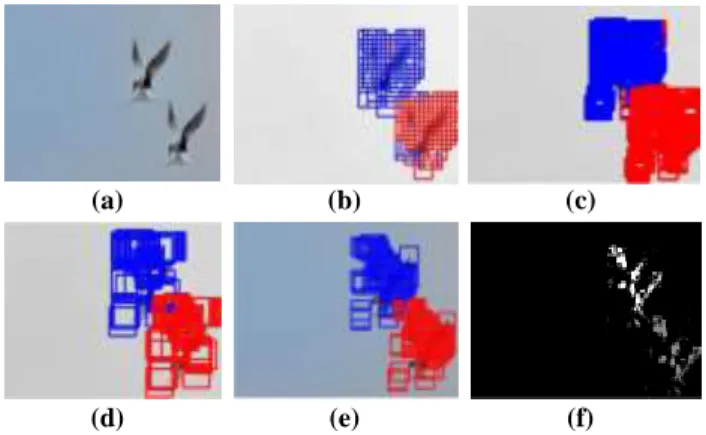
The detected results over tampered bird image for all DWT levels are shown in Figure 7.
(1)
34
(a) (b) (c)
(d) (e) (f)
Figure 7.Forgery detection result (a) tampered image (b) detection result on LLL level image (c) detection result onLLL-1 level image (d) detection result on LLL-2 level image (e) detection result on tampered image(f)Duplication map of detected result
The Figure 7(f) shows the duplication map for the detected result.
The duplication map gives clue about the number of pixels which are been copied and pasted to perform forgery. The white and gray colors have been used to show copied and its corresponding pasted regions. This can be used to assess the applicability of the proposed method when many pixels have been cloned in an image.
To see how this method performs under the noise modifications, we have used US currency note image to illustrate detection as shown in Figure 8.
(a) (b) (c)
(d) (e) (f)
Figure 8. Forgery detection result (a) original image
(b) tampered image(c) detection result with 15% normal noise(d) detection result with 25% normal noise(e) detection result with 35% normal noise (f) detection result with 45%
normal noise
The Figure 9 shows the performance of the algorithm for the image having more than one duplicated regions.
(a) (b) (c)
Figure 9. Forgery detection result (a) original image (b) tampered image having more than one duplicated result
To examine how this method performs under the blurring modification performed after the forgery is shown in Figure 10.
(a) (b) (c)
Figure 10. Forgery detection result (a) original image (b) tampered blurred image (c) detection result
3.1 Comparison with Existing Approaches In this section, we shall compare our approach with other existing one. The image used for the comparison is of size 128×128. Table 1 lists the comparison results.
Table 1. Comparison Results of the Two Approaches Algorithm Image
representa- tion
Block size
Block number
Feature dimens-
ion
Popescu[4] PCA 16×16 12769 128
Proposed DWT 8×8 3249 64
As is well known, the sort matrix scale is the major factor affecting the computation complexity. The total amount of its rows denotes block number, and the total amount of columns denote feature dimension.
In our approach selected block size for 128×128 size image is 8 × 8 on DWT first level. Then, it will become 16×16 on original image but sorted matrix size is less because of region comparisons. From Table I, it is obvious that the sort matrix in our approach is smaller in size than those in other two approaches under the same experimental condition.
3.2 Effect of the normal noise values on the detection time
The first comparative test evaluates the performance of the algorithm under different normal noise values. The test image is saved in JPEG format. The original test image with forged image and its corresponding results for PCA and our method is shown in Figure 11.
For this testing, the block size, b, was set dynamically based on image size. The value of block size is doubled in the next level of DWT and this process of block value continues until final image (highest resolution) is reached for final detection.
The normal noise (Nn) values added after forgery in Adobe Photoshop varied from 0 <= Nn <= 12 measured in percentage.
The Time for detection (Td) under different normal noise values are computed and plotted in Figure 12.
35 0
100 200 300 400 500
2 4 6 8
Detection Time(seconds)
JPEG quality levels(%)
Detection Time Comparison for Birds Image
Detection Time for PCA
Detection Time for DWT
0 100 200 300 400
0 4 8 12
Detection Time (seconds)
Normal noise levels(%)
Detection Time Comparison for Birds image
Detection Time for PCA
Detection Time for DWT
Figure 11. Forgery detection result (a) original bird image (b) tampered image (c) detection result for PCA method (d) detection result for DWT based method
Figure 12.Detection time comparison under different normal noise (Nn) levels
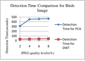
3.3 Effect of the JPEG quality levels on the detection time
The second comparative test evaluates the performance of the algorithm for tampered images saved under different JPEG quality levels (Jq).
The JPEG quality levels varied from 2<= Jq <= 8 measured in percentage. The Time for detection (Td) under different JPEG quality level values are computed and plotted in Figure 13.
The JPEG quality level variation is one form of retouching applied after forgery is performed. It is significantly important to check applicability of the proposed method for these kind of retouching techniques.
Figure 13.Detection time comparison under different JPEG quality (Jq) levels
From the results of Figure 12 and Figure 13, we can find that the proposed method works soundly for different retouching scenarios like JPEG quality level changes and normal noise change values.
It has been observed that when the amount of noise adding increases its corresponding time for detection decreases whereas for increased JPEG quality levels it‟s time for detection also increases.
3.4 Detection on an image having natural duplication
The applicability of any copy-move forgery algorithm depends highly upon the requirement that it should detect forged duplicated regions in an image but it should not detect regions which have natural or original duplication in them.
The Figure 14 shows the result of detection using PCA and DWT based proposed method for twin tower image where the image has original duplicated region in it.
(a) (b) (c)
Figure 14. Forgery detection result (a) original twin tower image (b) detection result for PCA method (d) detection result for DWT based method
3.5. Qualitative samples based on realistic forgeries
The following three “credible forgeries” have been created to qualitatively test the algorithm. Figure 15 shows the duplicate
(a) (b)
(c) (d)
(d)
36
regions identified where first row shows the result for normal noise corrupted image.
6. CONCLUSIONS
In this paper an algorithm for detecting copy move forgery using wavelet transforms is proposed. Our algorithm has lower computational complexity that means this is optimized version of the algorithm proposed in [1] since exhaustive search for identical blocks is performed only on the image at the lowest resolution.
This algorithm works even for the images where the attacker has made detection more difficult by applying noise and JPEG quality level changes. Experiments and analysis prove that the proposed method have nice robustness to common post processing operations. Although duplicated regions with rotation through angles and scaled regions cannot be detected.
In the future, we would like to search for some mechanism to deal with these problems. In addition to this, the same can be extended to work on videos where search for duplicated blocks has to perform on multiple image frames.
With the development of digital forgery technology, digital detection keeping place with digital tampering is difficult only depending on single digital forensic tool. The future digital forensic direction would be multiplex forensic tools in conjunction with awareness and sensible policy and law to create convincing digital forgeries.
7. REFERENCES
[1] Myna.A.N. , M.G.Venkateshmurthy , C.G.Patil
“Detection of Region Duplication Forgery In Digital Images Using Wavelets and Log-polar Mapping”, in
Proc. of International Conference on Computational Intelligence and Multimedia Applications,Volume 3, 13- 15 ,pp.371– 377, July 2-6, 2007.
(a) Original Image (b) Forged Image (c) Result for DWT method (d) Result for PCA method Figure 15. Credible Forgeries Created for Qualitative Analysis of the proposed algorithm
[2]
Sarah A. Summers, Sarah C. Wahl “Multimedia Security and Forensics Authentication of Digital Images”
http://cs.uccs.edu/~cs525/studentproj/proj52006/sasumme r/doc/cs525projsummersWahl.doc
[3] J. Fridrich, D. Soukal, and J. Lukas, “Detection of copy- move forgery in digital images,” Proceedings of the Digital Forensic Research Workshop. Cleveland OH, USA, 2003.
[4] A.C.Popescu and H.Farid, “Exposing digital forgeries by detecting duplicated image regions,” Dartmouth College, Hanover, New Hampshire, USA: TR2004-515, 2004.
[5] G.Li, Q.Wu, D.Tu, and Shaojie Sun, “A sorted neighborhood approach for detecting duplicated regions in image forgeries based on DWT and SVD,” IEEE International Conference on Multimedia & Expo, 2007.
[6] Talbert, D. A. and Fisher, D., “An empirical analysis of techniques for constructing and searching k-dimensional trees”, in ACM SIGKD international conference on Knowledge discovery and data mining, pp 26-33, 2000.
[7] Jung, I-K. and Lacroix, S., “A Robust Interest Point Matching Algorithm”, in International Conference on Computer Vision. 2001.
[8] Rafael C. Gonzalez, Richard E. Woods, Steven L.
Eddins,“Digital Image Processing using MATLAB”,Second Edition, Pearson Publications, 2004.
[9] (2010, April.).”Phase correlation”[online].Available:
http”//en.wikipedia.org/wiki/Phase correlation