國立臺灣大學電機資訊學院資訊工程學系 碩士論文
Department of Computer Science and Information Engineering College of Electrical Engineering and Computer Science
National Taiwan University Master Thesis
多頻道無線網狀網路之分散式頻道分配機制
Distributed Channel Assignment in Multi-channel Wireless Mesh Network
鍾依芳 Chung Yi-Fang
指導教授:逄愛君 博士 Advisor: Pang Ai-Chun, Ph.D.
中華民國 100 年 7 月
July, 2011
Acknowledgments
I wish to express my appreciation to many people who have assisted and supported me with this thesis. First of all, I would like to express my sin- cere gratitude to my advisor, Professor Ai-Chun Pang, whose inspiring guid- ance led me to the right direction of the research. Her generous assistance and invaluable suggestions helped me overcome many situations and made it possible to finish this thesis. I would also like to thank my master thesis committee, Prof. Tei-Wei Kuo and Prof. Pi-Cheng Hsiu. With their precious comments, my work can be more improved and complete.
In addition, I would like to thank all members in laboratory 438 and 442.
They have given me great help and support. I appreciate Chiu-Hua for her assistance and encouragement helped me defeat frustration and stay focused on my research. Moreover, thanks to my best friends who have always stood by me, thus I have the courage to face difficulties.
Finally, I would deliver my ultimate sincere gratitude to my beloved fam- ily. With their boundless love and support over the last two years, I can concentrate on my work.
中
中 中文 文 文摘 摘 摘要 要 要
在IEEE 802.11中,頻道資源是十分有限且珍貴的。因此在多頻道 無線網狀網路下,為了能夠充分利用可用的頻道,頻道分配機制成為 一項重要的研究議題。頻道分配可分為集中式及分散式兩種方式。本
論文採用分散式頻道分配,每一個節點根據局部的資訊來選擇自己欲
使用的頻道。分散式頻道分配的優點是擁有較大的彈性和容錯性。然
而,「頻道振盪」是分散式頻道分配機制的主要問題,此問題為節點 反覆地改變頻道,導致頻道分配經過一段長時間後,仍無法達到穩 定,網路的吞吐量因此受到限制。在本論文中,我們提出了一個新的 分散式頻道分配機制,能夠有效的解決頻道振盪問題,並提高網路吞 吐量。實驗結果證實,我們所提出的方法無論在網路吞吐量或點對點 的延遲時間上,都比先前提出的分散式頻道分配機制具有更好的效 能。
關關關鍵鍵鍵詞詞詞: 分散式頻道分配, 頻道振盪, 多頻道多網卡, 部份重疊頻道, 無線網狀網路
Abstract
In IEEE 802.11, channel resources are very limited and scarce. Thus channel assignment schemes which can effectively utilize available channels is one of the important issues in multi-channel wireless mesh networks. There are two approaches for channel assignment: centralized and distributed. We focus on distributed channel assignment, i.e., each node chooses its channel based on local information. The advantages of distributed approach are better flexibility and fault-tolerance. However, the problem of distributed channel assignment is channel oscillation which results that the channel assignment cannot converge for a long time and nodes change its channel repeatedly, and therefore the network throughput is throttled. In this thesis, we propose a new distributed channel assignment scheme to solve the channel oscillation problem, and to maximize the network throughput. Performance evaluation shows that our proposed algorithm improves the throughput and end-to-end delay in comparison to previously proposed distributed channel assignment schemes.
keywords: Distributed channel assignment, channel oscillation, multi- channel multi-interface, partially overlapping channels, wireless mesh net- work.
Contents
口 口
口試試試委委委員員員會會會審審審定定定書書書 i
Acknowledgments ii
中 中
中文文文摘摘摘要要要 iii
Abstract iv
1 Introduction 1
2 Related Work 3
3 System Model 5
3.1 Network Architecture . . . 5
3.2 Partially Overlapping Channels . . . 6
4 Proposed Algorithm 8 4.1 Overview . . . 8
4.2 Priority Determination Phase . . . 9
4.3 Fixed Channel Assignment Phase . . . 10
4.3.1 Interference Calculation . . . 12
4.3.2 Channel Assignment . . . 12
5 Performance Evaluation 15 5.1 Simulation Environment . . . 15
5.1.1 Set Acceptable Threshold . . . 16
5.1.2 Performance Metrics . . . 17
5.2 Simulation Results . . . 21
6 Conclusion 25
Bibliography 26
List of Figures
3.1 Wireless mesh networks architecture . . . 6 4.1 The example of priority determination . . . 11 5.1 Acceptable threshold under varying numbers of nodes (data rate: 512kbps) 18 5.2 Acceptable threshold under varying numbers of nodes (data rate: 1Mbps) 19 5.3 Acceptable threshold under varying numbers of nodes (data rate: 3Mbps) 20 5.4 Throughput under varying data rates . . . 23 5.5 End-to-end delay under varying data rates . . . 24
List of Tables
4.1 Channel Overlapping Degree . . . 12 5.1 Simulation Parameters . . . 16
Chapter 1 Introduction
Wireless mesh networks [1] have become a popular technology for many applications, such as broadband home networking, enterprise networking, building automation, and so on. There is one common problem in wireless mesh networks: the throughput is limited due to the interference of neighboring links that transmit simultaneously. Therefore, effi- ciently utilizing the available spectrum resources is needed, channel assignment becomes an important issue in wireless mesh networks.
Channel assignment approaches can be classified into two categories: centralized and distributed. Centralized channel assignment [2][18] requires a controller which is used to collect the information of the network and assign the channels for each node. The disadvantage of this approach is that the controller may be overloaded and the failure of the controller makes the network unworkable. In this thesis, we adopt the distributed channel assignment.
The challenge of distributed channel assignment is the channel oscillation problem, which results that channel assignment repeatedly changes and unstable for a long time.
Since the nodes do not know the operations of each other, when nodes discover that a channel is with minimum interference, they may change to that channel simultaneously.
The changing to the same channel will increase the interference level of that channel, and thus decrease the throughput gain. Therefore, these nodes will change channel with
minimum interference again. In this situation, channel allocation does not converge, the transmission of nodes may be interrupted, and that will constrain the throughput gain.
In this thesis, we propose a distributed channel assignment algorithm which can deter- mine the priority of nodes and ensure that the only one node can change its channel in its interference range to avoid the channel oscillation problem. Simulation results indicate that in terms of throughput and end-to-end delay, our algorithm performs much better than previously proposed algorithms [11] [12] [13].
The rest of this thesis is organized as follows. Chapter 2 describes the related work. In chapter 3, we describe our system model. Then we present our distributed channel assign- ment algorithm in Chapter 4. Chapter 5 summarizes our simulation results to demonstrate the performance of the proposed algorithm. Finally, we conclude our work in chapter 6.
Chapter 2
Related Work
In contrast to centralized channel assignment, distributed channel assignment does not require the central controller; each node performs channel assignment only considering local information. In this way, distributed channel assignment avoids the bottleneck of controller and flexibly overcomes the failure of nodes.
In this chapter, we summarize the distributed channel assignment schemes for wire- less mesh networks. Raniwala et al. [17] proposed a distributed channel assignment and tree-based routing scheme, which considers the network traffic load to assign channels.
This scheme can improve the aggregate network throughput and balance load among gate- way. Dhananjay et al. [7] proposed a distributed protocol that chooses gateway paths and assigns channel. The protocol ensures that each gateway path consists of high link deliv- ery ratio links operating on different channels. Liu et al. [12][13] proposed distributed channel assignment algorithms using partially overlapping channels, and their simula- tion results showed that the throughput is better than the centralized channel assignment.
However, aforementioned distributed channel assignment schemes did not consider the channel oscillation problem.
Ko. et al. [3] and Subramanian et al. [19] proposed distributed channel assignment algorithms, which considered the channel oscillation problem. Their algorithms constrain each node can changes channel only once. Although the channel assignment is stable,
the network interference is still large since each node may change to the same channel simultaneously, and still suffers larger interference. Our proposed distributed channel assignment algorithm focus on solving the channel oscillation problem. Our objective is to stabilize channel assignment and maximize the network throughput.
Chapter 3
System Model
3.1 Network Architecture
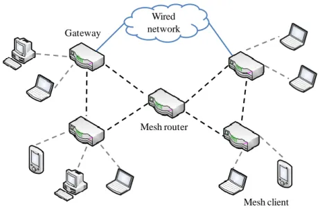
Our distributed channel assignment algorithm is based on wireless mesh network. A wireless mesh network consists of three types of nodes: mesh routers, gateways and mesh clients. Mesh routers are stationary which provide connectivity between gateways and mesh clients. Some of the mesh routers are called gateways, which are used to connect to the wired network. Since most of the traffic is directed to/from wired network, gateways have the heaviest load in the network. Mesh clients can be stationary or mobile and they connect to the wired network through the mesh routers. The architecture of a wireless mesh network is depicted in Figure 3.1.
We adopt hybrid channel assignment scheme [11]. Each node is equipped with two in- terfaces in the wireless mesh network. One is the fixed interface, which is used to receive packets. The other one is the switchable interface, which is used to send packet. When a node has a packet to transmit, it switches its switchable interface to the fixed channel of the receiver. This scheme is more flexible and fault-tolerant. Unlike static channel assignment [18] which assigns a channel to each interface permanently. Therefore, when two nodes operating on different channels, they cannot communicate with each other.
Besides, the failure of a node may cause network partition.
Wired network
Mesh router
Mesh client Gateway
Figure 3.1: Wireless mesh networks architecture
3.2 Partially Overlapping Channels
The IEEE 802.11b/g standards operate in the ISM 2.4GHz band which have 11 available channels. Each channel is 22MHz wide and the central frequencies are separated by 5MHz. If the channel separation is larger than 22MHz, two channels do not interfere with each other, which are called non-overlapping channels. Otherwise, they are called partially overlapping channels. Thus, the maximum number of available non-overlapping channels is three, namely channel 1, 6 and 11.
Traditionally, each node in the interference range uses different non-overlapping chan- nels to avoid interference. If they operate on the same channel, they use RTS/CTS mecha- nism to solve interference. Although the interference is avoided, there are other available channels are wasted.
Mishra et al. [14][15] proposed exploiting partially overlapping channels on the acceptable interference level, which is beneficial to improve the network performance, since the number of simultaneous transmissions can be increased. The simulation re- sults showed that the network throughput can be increased further than only using non-
overlapping channels. Hoque et al. [10] and Duarte et al. [9] proposed centralized chan- nel assignment algorithms using partially overlapping channels, their simulation results showed the number of links and network throughput are improved. Liu et al. [12][13]
proposed distributed channel assignment algorithms using partially overlapping channels, the results shown the throughput is better than the centralized channel assignment algo- rithms which use non-overlapping channels or partially overlapping channels.
Therefore, intelligently assign partially overlapping channels can improve network performance. Our distributed channel assignment algorithm is concerned with partially overlapping channels in wireless mesh networks.
Chapter 4
Proposed Algorithm
In this chapter, we present our distributed channel assignment algorithm. We first describe our design and then present the procedure of channel assignment in detail. The algorithm utilizes only local information to perform channel assignment. The information is col- lected from the nodes in the interference range that is set to two hops.
4.1 Overview
According to the characteristics of traffic loads in wireless mesh networks, gateway has the heaviest traffic load in the networks. Therefore, gateway may becomes the bottleneck if its channel suffers larger interference. Under this assumption, gateway has the highest priority to choose a channel with minimum interference in our algorithm, followed by the one-hop nodes away from the gateway, and then the two-hop nodes away from the gateway. Thus, the nodes farthest from the gateway have the lowest priority in channel assignment.
The channel oscillation problem in distributed channel assignment is described in chapter 1. In order to stabilize the channel allocation, we propose a mechanism that can achieve it. That is when a node changes its fixed channel, no other nodes can change simultaneously in its interference range.
fixed channel assignment phase. In priority determination phase, the channel assignment priority of each node is determined. In fixed channel assignment phase, the fixed interface of each node is assigned a channel without channel oscillation.
4.2 Priority Determination Phase
At the beginning, each node randomly chooses its fixed channel, then it broadcasts a HELLO packet to other nodes in its interference range to inform its ID and fixed channel information. Based on the received HELLO packet, each node can collects the local information to choose a channel with minimum interference.
In our algorithm, we through modify the HELLO packet to determine the priority of each node. The modified HELLO packet includes the original ID and fixed channel.
Besides, we add two new fields: hop count and flag. The hop count is the number of hops to the gateway. Initially, the gateway’s hop count is set to 0, and other mesh routers’ hop count is set to ∞. The flag is used to indicate whether the packet come from a gateway or mesh routers. The gateway’s flag is set to 1, and other mesh routers’ flag is set to 0.
When a node receives modified HELLO packet, it can recognize the sender’s ID and fixed channel, then use the flag and hop count to determine the number of hops to the gateway.
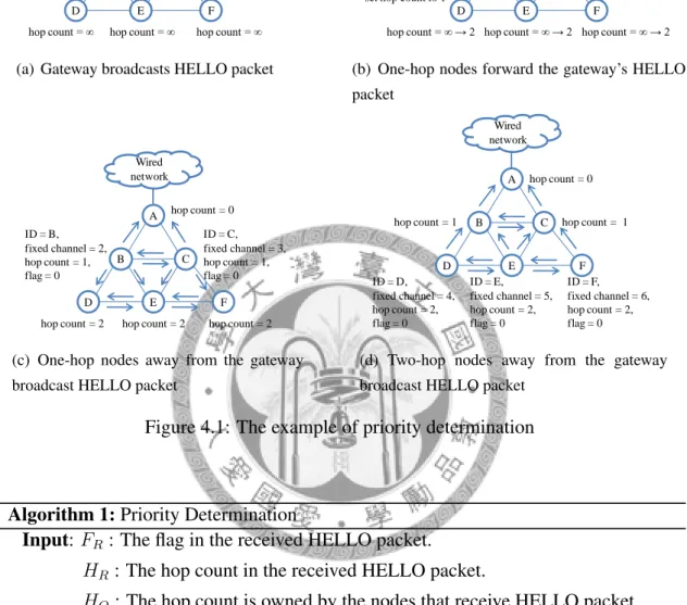
In the first step, the gateway broadcasts modified HELLO packet with the hop count is 0 and the flag is 1 to all nodes in its interference range (two hops). When the one-hop nodes away from the gateway receive the HELLO packet, they detect the received flag is 1 that indicates the packet coming from a gateway. Therefore, one-hop nodes set their hop count with the value of hop count in the received HELLO packet plus 1 (Figure 4.1(a)).
Then, the one-hop nodes forward the gateway’s HELLO packet, and set the hop count is 1. When two-hop nodes receive the HELLO packet, they detect the flag is 1 that means the packet coming from the gateway, so they set their hop count to 2 (Figure 4.1(b)).
In the next step, the one-hop nodes away from the gateway broadcast modified HELLO packet with the hop count is 1 and the flag is 0. When a gateway receiving the flag is 0, which indicates the packet coming from a mesh router, therefore gateway’s hop count un- changed. When a mesh router node receiving the flag is 0, which means that both of them are mesh routers, and then compare the received hop count with its own hop count. If the value of received hop count is smaller than its own hop count, and the value of its own hop count is ∞, which indicates the packet coming from a two-hop nodes away from the receiving node. The receiving node set their hop count with the value of hop count in the received HELLO packet plus 1. Otherwise, the hop count unchanged. (Figure 4.1(c)).
Thereafter, the two-hop nodes away from the gateway broadcast modified HELLO packet. When the other nodes receive the packet, they will determine how to reset their hop count (Figure 4.1(d)). In this way, all nodes broadcast HELLO packet in sequence, the hop count of each node is decided. Therefore, the priority of each node is determined, since gateway node has the smallest value of hop count, it is allocated the highest priority, and the nodes have the largest value of hop count, they are allocated the lowest priority.
An example for determine the hop count is shown in Figure 4.1. The algorithm is shown in Algorithm 1.
4.3 Fixed Channel Assignment Phase
In this phase, each node’s fixed interface is assigned a channel via two steps. The first step is to calculate the interference level of each node with different channels. The second step is assigning the chosen channel with minimum interference to each node without channel oscillation.
Wired network
B C
D E F
A
ID = A, fixed channel = 1, hop count = 0, flag = 1
hop count = ∞ → 1 hop count = ∞ → 1
hop count = ∞ hop count = ∞ hop count = ∞ HELLO
(a) Gateway broadcasts HELLO packet
Wired network
B C
D E F
A
hop count = 1 hop count = 1
hop count = ∞ → 2 Forward A’s HELLO, set hop count to 1
hop count = ∞ → 2 hop count = ∞ → 2
(b) One-hop nodes forward the gateway’s HELLO packet
Wired network
B C
D E F
A ID = B,
fixed channel = 2, hop count = 1, flag = 0
hop count = 0
hop count = 2 hop count = 2 hop count = 2 ID = C, fixed channel = 3, hop count = 1, flag = 0
(c) One-hop nodes away from the gateway broadcast HELLO packet
Wired network
B C
D E F
A
ID = D, fixed channel = 4, hop count = 2, flag = 0
hop count = 1 hop count = 1 hop count = 0
ID = E, fixed channel = 5, hop count = 2, flag = 0
ID = F, fixed channel = 6, hop count = 2, flag = 0
(d) Two-hop nodes away from the gateway broadcast HELLO packet
Figure 4.1: The example of priority determination
Algorithm 1: Priority Determination
Input: FR: The flag in the received HELLO packet.
HR: The hop count in the received HELLO packet.
HO: The hop count is owned by the nodes that receive HELLO packet.
Output: hop count
1 if FR= 1then
2 hop count = HR+ 1
3 else if HR< HO&&HO == ∞ then
4 hop count = HR+ 1
5 else
6 hop count unchanged
7 end
8 end
9 end
10 return hop count
4.3.1 Interference Calculation
After the priority determination phase, all nodes can start channel assignment according to the priority. We utilizing Burton [5] proposed channel overlapping degree to calculate the interference level of each node with different channels. The channel overlapping degree is shown in Table 4.1. The level of interference is calculated by the equation 4.1 as defined below. Interf erence[i][c] is the total interference that node i suffers from the nodes in its interference range when channel c is assigned to node i. O[ic][j] is the channel overlapping degree between the channels used by node i and node j. B[j] is the active time of node j. Each node calculates its interference level by equation 4.1, and it chooses the channel with minimum interference as its fixed channel.
Interf erence[i][c] = X
j∈I(i)
O[ic][j] ∗ B[j] (4.1)
Channel Separation 0 1 2 3 4 5 6 7∼10
Overlapping Degree 1 0.7272 0.2714 0.0375 0.0054 0.0008 0.0002 0 Table 4.1: Channel Overlapping Degree
4.3.2 Channel Assignment
In this step, we assign the chosen channel to the fixed interface of each node. In order to solve the channel oscillation problem, we define a constraint: there are only one node can changes its channel in its interference range. Besides, when a node changes its fixed channel may affect other nodes in its interference range suffer larger interference. Thus, in our algorithm, when a node wants to change its fixed channel with a minimum interfer- ence, it needs to ask other nodes in its interference range whether the change will make them suffer larger interference.
We propose three messages: REQUEST, ACCEPT and REJECT. Each node exchanges
to reply whether the request is agreed. The definitions of these messages are as follows:
• REQUEST: when a node wants to change its fixed channel, it sends the message to request the other nodes in its interference range to remain in the current channel until it completes the change.
• ACCEPT: when a node receives a REQUEST message, if the change will make it suffers smaller interference than before, it replies with the message to inform this change request is agreed.
• REJECT: when a node receives a REQUEST message, if the change will make it suffers larger interference than before, it replies with the message to inform this change request is refused.
When a node receives a REQUEST, it decides to reply with ACCEPT or REJECT. If the node suffers smaller interference than before, it replies with ACCEPT. Otherwise, it replies with REJECT. When the requesting node receives the reply, it will decide whether to change its channel. In our algorithm, we set an acceptable threshold, and the request- ing node calculates its accept ratio by equation 4.2. If the accept ratio larger than the acceptable threshold, which indicates for most of nodes in the interference range, their interference level is better than before. Therefore, requesting node can change its chan- nel; otherwise, requesting node stays on the original channel. Finally, the requesting node broadcasts HELLO packet to other nodes in its interference range to inform its current channel. The algorithm is shown in Algorithm 2.
accept ratio = the number of ACCEP T
(the number of ACCEP T + the number of REJ ECT ) (4.2)
Algorithm 2: Fixed Channel Assignment
Input: Interf erenceold[j] : the interference of node j suffers before the node request to change channel.
Interf erencenew[j] : the interference of node j suffers if the requesting node change its channel.
Ath: the acceptable threshold.
Ai: the accept ratio.
Output: Assign each node’s fixed channel
1 if Interf erencenew[j] <= Interf erenceold[j] then
2 return ACCEPT
3 else
4 return REJECT
5 end
6 end
7 if Ai > Aththen
8 requesting node changes its fixed channel
9 else
10 requesting node aborts to change fixed channel
11 end
12 end
Chapter 5
Performance Evaluation
In this chapter, we describe our simulation environment, and demonstrate the value of acceptable threshold. Finally, we investigate the performance of our proposed distributed channel assignment, and compared it with the distributed channel assignment scheme which uses non-overlapping channels [11], CAEPO [12] and CAEPO-S [13] which use partially overlapping channels.
5.1 Simulation Environment
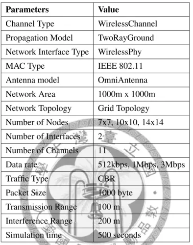
We use ns-2 to evaluate the performance of the proposed algorithm, and we modify ns- 2 to support multi-channel and multi-interface environment [6]. In our simulation, the network is a grid topology and the network area is 1000m x 1000m. Each node is equipped with two interfaces, and it uses WirelessChannel with IEEE 802.11 MAC protocol and WirelessPhy layer. The transmission range of each node is 100m, and the interference range of each node is 200m. The number of available channels is set to 11. Besides, the simulation uses the TwoRayGround propagation model and an omni-directional antenna.
Our simulation time is set to 500 seconds. The simulation parameters are summarized in Table 5.1.
We randomly choose the source and destination node pairs in the network. The traffic is generated by constant bit rate (CBR), and the packet size for all traffic is set to 1000
bytes. We vary the data rates (512kbps, 1Mbps and 3Mbps) and the numbers of nodes (7x7, 10x10, and 14x14) to evaluate the performance at different scenarios.
Parameters Value
Channel Type WirelessChannel Propagation Model TwoRayGround Network Interface Type WirelessPhy
MAC Type IEEE 802.11
Antenna model OmniAntenna Network Area 1000m x 1000m Network Topology Grid Topology Number of Nodes 7x7, 10x10, 14x14 Number of Interfaces 2
Number of Channels 11
Data rate 512kbps, 1Mbps, 3Mbps
Traffic Type CBR
Packet Size 1000 byte
Transmission Range 100 m Interference Range 200 m Simulation time 500 seconds
Table 5.1: Simulation Parameters
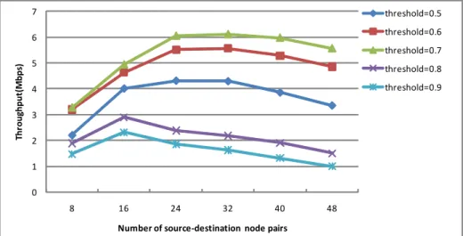
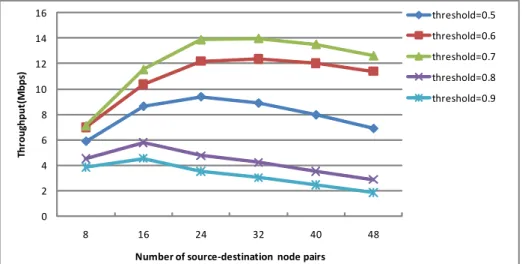
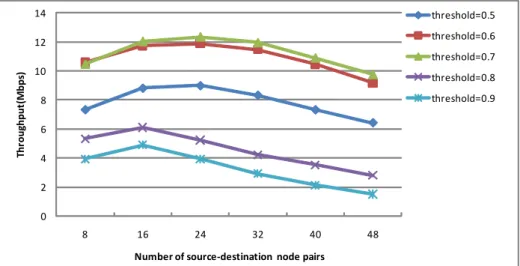
5.1.1 Set Acceptable Threshold
In our algorithm, we need to set the value of acceptable threshold. If the threshold is set too large, many nodes cannot change their fixed channel, and thus they still suffer larger interference. If the threshold is set too small, many nodes can change their fixed channel, which will increase the interference level of other nodes in its interference range.
Therefore, how to set the value of acceptable threshold is important. In this simulation, we consider with the varying numbers of nodes: 7x7, 10x10, 14x14 and varying data rates: 512kbps, 1Mbps, 3Mbps to evaluate the value of acceptable threshold.
The numbers of nodes are 7x7, 10x10 and 14x14. We can observe that when the value of acceptable threshold is set to 0.7, the throughput is the best of all, especially when the node density is high (Figure 5.1(c) and Figure 5.2(c)). In contrast, when the value of acceptable threshold is set to 0.8 or 0.9, the throughput is worse. Since the value of acceptable threshold is set too large, many nodes cannot change their fixed channel, and they still suffer larger interference.
In Figure 5.3, we use the saturated data rate is 3Mbps. The numbers of nodes are 7x7, 10x10 and 14x14. We can observe that when the value of acceptable threshold is set to 0.6 or 0.7, the throughput is better than others, especially as the number of source-destination pairs is smaller, the values of throughput are close to each other. However, as the number of source-destination pairs increases, the throughput is the best of all when the value of acceptable threshold is set to 0.7. Therefore, the value of acceptable threshold is set to 0.7 in our simulation.
5.1.2 Performance Metrics
We evaluate our distributed channel assignment algorithm through two metrics: through- put and end-to-end delay. Our proposed algorithm is compared with the distributed chan- nel assignment scheme which uses non-overlapping channels [11], CAEPO [12], and CAEPO-S [13] which use partially overlapping channels.
• Throughput: the average number of packets is received successfully during a time unit.
• End-to-end delay: the time difference that a packet transmitted from the source to the destination.
0 1 2 3 4 5 6 7
8 16 24 32 40 48
Throughput(Mbps)
Number of source-destination node pairs
threshold=0.5 threshold=0.6 threshold=0.7 threshold=0.8 threshold=0.9
(a) The number of nodes: 7x7
0 2 4 6 8 10 12
10 30 50 70 90 110
Throughput(Mbps)
Number of source-destination node pairs
threshold=0.5 threshold=0.6 threshold=0.7 threshold=0.8 threshold=0.9
(b) The number of nodes: 10x10
0 5 10 15
10 50 90 130 170 210
Throughput(Mbps)
Number of source-destination node pairs
threshold=0.5 threshold=0.6 threshold=0.7 threshold=0.8 threshold=0.9
(c) The number of nodes: 14x14
Figure 5.1: Acceptable threshold under varying numbers of nodes (data rate: 512kbps)
0 2 4 6 8 10 12 14 16
8 16 24 32 40 48
Throughput(Mbps)
Number of source-destination node pairs
threshold=0.5 threshold=0.6 threshold=0.7 threshold=0.8 threshold=0.9
(a) The number of nodes: 7x7
0 5 10 15 20 25
10 30 50 70 90 110
Throughput(Mbps)
Number of source-destination node pairs
threshold=0.5 threshold=0.6 threshold=0.7 threshold=0.8 threshold=0.9
(b) The number of nodes: 10x10
0 5 10 15 20 25 30 35
10 50 90 130 170 210
Throughput(Mbps)
Number of source-destination node pairs
threshold=0.5 threshold=0.6 threshold=0.7 threshold=0.8 threshold=0.9
(c) The number of nodes: 14x14
Figure 5.2: Acceptable threshold under varying numbers of nodes (data rate: 1Mbps)
0 2 4 6 8 10 12 14
8 16 24 32 40 48
Throughput(Mbps)
Number of source-destination node pairs
threshold=0.5 threshold=0.6 threshold=0.7 threshold=0.8 threshold=0.9
(a) The number of nodes: 7x7
0 5 10 15 20
10 30 50 70 90 110
Throughput(Mbps)
Number of source-destination node pairs
threshold=0.5 threshold=0.6 threshold=0.7 threshold=0.8 threshold=0.9
(b) The number of nodes: 10x10
0 5 10 15 20 25
10 50 90 130 170 210
Throughput(Mbps)
Number of source-destination node pairs
threshold=0.5 threshold=0.6 threshold=0.7 threshold=0.8 threshold=0.9
(c) The number of nodes: 14x14
Figure 5.3: Acceptable threshold under varying numbers of nodes (data rate: 3Mbps)
5.2 Simulation Results
In the simulation, we consider with the number of nodes is 10x10, and varying data rates:
512kbps, 1Mbps and 3Mbps to measure the throughput and end-to-end delay.
Figure 5.4 shows that under different date rates, as the number of source-destination node pairs increases, the throughput of partially overlapping channels is better than that of non-overlapping channels, since the number of simultaneous transmissions increases.
Besides, our algorithm is also better than CAEPO and CAEPO-S which use partially over- lapping channels. Since we solve the channel oscillation problem, channel assignment can be stabilized shortly, and the transmission of nodes is not interrupted, throughput can be improved. In Figure 5.4(a), the data rate is 512kbps. Our algorithm improves the ra- tio of throughput about 12% than CAEPO-S. In Figure 5.4(b), the data rate is 1Mbps.
Our algorithm improves the ratio of throughput about 18% than CAEPO-S. In Figure 5.4(c), the data rate is 3Mbps. Our algorithm improves the ratio of throughput about 26%
than CAEPO-S. Moreover, we compare the throughput of 3Mbps with the throughput of 1Mbps, we can observe that the throughput of 3Mbps does not increase, which indicates that 3Mbps is a saturated data rate. Thus, the data rate exceeding the saturated rate does not help to improve the throughput.
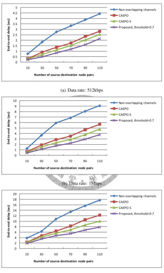
Figure 5.5 illustrates the end-to-end delay with varying data rates. We can observe the end-to-end delay of partially overlapping channels is lower than that of non-overlapping channels. Since we utilize all available channels can effectively reduce the network con- tention, the network latency can be decreased. Besides, our algorithm is also better than CAEPO and CAEPO-S. Since we solve the channel oscillation problem, the transmission of nodes is not interrupted, and the nodes do not need to wait for the time of channel change, end-to-end delay can be decreased. In Figure 5.5(a), the data rate is 512kbps.
Our algorithm improves the ratio of end-to-end delay about 20% than CAEPO-S. In Fig-
ure 5.5(b), the data rate is 1Mbps. Our algorithm improves the ratio of end-to-end delay about 22% than CAEPO-S. In Figure 5.5(c), the data rate is 3Mbps. Our algorithm im- proves the ratio of end-to-end delay about 21% than CAEPO-S.
0 2 4 6 8 10 12
10 30 50 70 90 110
Throughput(Mbps)
Number of source-destination node pairs
Non-overlapping channels CAEPO
CAEPO-S
Proposed,threshold=0.7
(a) Data rate: 512kbps
0 5 10 15 20 25
10 30 50 70 90 110
Throughput(Mbps)
Number of source-destination node pairs
Non-overlapping channels CAEPO
CAEPO-S
Proposed,threshold=0.7
(b) Data rate: 1Mbps
0 5 10 15 20
10 30 50 70 90 110
Throughput(Mbps)
Number of source-destination node pairs
Non-overlapping channels CAEPO
CAEPO-S
Proposed, threshold=0.7
(c) Data rate: 3Mbps
Figure 5.4: Throughput under varying data rates
0 0.5 1 1.5 2 2.5 3 3.5 4 4.5 5
10 30 50 70 90 110
End-to-end delay (sec)
Number of source-destination node pairs
Non-overlapping channels CAEPO
CAEPO-S
Proposed, threshold=0.7
(a) Data rate: 512kbps
0 1 2 3 4 5 6 7 8 9 10
10 30 50 70 90 110
End-to-end delay (sec)
Number of source-destination node pairs
Non-overlapping channels CAEPO
CAEPO-S
Proposed, threshold=0.7
(b) Data rate: 1Mbps
0 2 4 6 8 10 12 14 16 18 20
10 30 50 70 90 110
End-to-end delay (sec)
Number of source-destination node pairs
Non-overlapping channels CAEPO
CAEPO-S
Proposed, threshold=0.7
(c) Data rate: 3Mbps
Figure 5.5: End-to-end delay under varying data rates
Chapter 6 Conclusion
Channel oscillation is one of the major problems in distributed channel assignment. In this thesis, we proposed a distributed channel assignment algorithm utilizing partially overlapping channels for wireless mesh networks. Our algorithm can stabilize channel allocation. The algorithm consists of two phases: priority determine phase and fixed channel assignment phase. In the priority determine phase, we modify the HELLO packet to determine the priority. In the fixed channel assignment phase, we proposed REQUEST, ACCEPT and REJECT messages to solve the channel oscillation problem. Simulation results showed that our algorithm can improve the throughput by about 19%, and reduce the end-to-end delay by about 21% compared to the previously proposed scheme.
Bibliography
[1] I. F. Akyildiz, X. Wang, and W. Wang. Wireless mesh networks: a survey. In Computer Networks, 47(4):445–487, 2005.
[2] M. Alicherry, R. Bhatia, and L. E. Li. Joint channel assignment and routing for throughput optimization in multi-radio wireless mesh networks. In Proceedings of the 11th annual international conference on Mobile computing and networking (MobiCom), pages 58–72, 2005.
[3] K. Bong-Jun, V. Misra, J. Padhye, and D. Rubenstein. Distributed channel assign- ment in multi-radio 802.11 mesh networks. In Proceedings of IEEE Wireless Com- munications and Networking Conference (WCNC), pages 3978–3983, 2007.
[4] V. Bukkapatanam, A. A. Franklin, and C. S. R. Murthy. Using partially overlapped channels for end-to-end flow allocation and channel assignment in wireless mesh networks. In Proceedings of the IEEE international conference on Communications (ICC), pages 4650–4655, 2009.
[5] M. Burton. Channel overlap calculations for 802.11b networks. Whiter paper, Cirond Technologies Inc, 2002.
[6] R. A. Calvo and J. P. Campo. Adding multiple interface support in ns-2. http:
//personales.unican.es/aguerocr/, 2007.
[7] A. Dhananjay, H. Zhang, J. Li, and L. Subramanian. Practical, distributed channel assignment and routing in dual-radio mesh networks. In Proceedings of the ACM SIGCOMM 2009 conference on Data communication, pages 99–110, 2009.
[8] Y. Ding, Y. Huang, G. Zeng, and L. Xiao. Channel assignment with partially over- lapping channels in wireless mesh networks. In Proceedings of the 4th Annual In- ternational Conference on Wireless Internet (WICON), pages 38–46, 2008.
[9] P. B. F. Duarte, Z. M. Fadlullah, K. Hashimoto, and N. Kato. Partially overlapped channel assignment on wireless mesh network backbone. In Proceedings of the IEEE Global Communications Conference (GLOBECOM), pages 1–5, 2010.
[10] M. A. Hoque, X. Hong, and F. Afroz. Multiple radio channel assignment utilizing partially overlapped channels. In Proceedings of the IEEE Global Communications Conference (GLOBECOM), pages 4737–4743, 2009.
[11] P. Kyasanur and N. H. Vaidya. Routing and interface assignment in multi-channel multi-interface wireless networks. In Proceeding of the IEEE Wireless Communica- tions and Networking Conference (WCNC), volume 4, pages 2051–2056, 2005.
[12] Y. Liu, R. Venkatesan, and C. Li. Channel assignment exploiting partially over- lapping channels for wireless mesh networks. In Proceedings of the IEEE Global Communications Conference (GLOBECOM), pages 5624–5628, 2009.
[13] Y. Liu, R. Venkatesan, and C. Li. Load-aware channel assignment exploiting par- tially overlapping channels for wireless mesh networks. In Proceedings of the IEEE Global Communications Conference (GLOBECOM), pages 1–5, 2010.
[14] A. Mishra, E. Rozner, S. Banerjee, and W. Arbaugh. Exploiting partially overlapping channels in wireless networks: turning a peril into an advantage. In Proceedings of
the ACM SIGCOMM conference on Internet Measurement, IMC ’05, pages 29–34, 2005.
[15] A. Mishra, V. Shrivastava, S. Banerjee, and W. Arbaugh. Partially overlapped chan- nels not considered harmful. In SIGMETRICS/Performance, pages 63–74, 2006.
[16] A. H. M. Rad and V. W. S. Wong. Partially overlapped channel assignment for multi-channel wireless mesh networks. In Proceedings of the IEEE International Conference on Communications (ICC), pages 3770–3775, 2007.
[17] A. Raniwala and T. cker Chiueh. Architecture and algorithms for an ieee 802.11- based multi-channel wireless mesh network. In IEEE INFOCOM, volume 3, pages 2223–2234, 2005.
[18] A. Raniwala, K. Gopalan, and T. cker Chiueh. Centralized channel assignment and routing algorithms for multi-channel wireless mesh networks. In ACM SIGMOBILE Mobile Computing and Communications Review, volume 8, pages 50–65, 2004.
[19] A. P. Subramanian, H. Gupta, S. R. Das, and J. Cao. Minimum interference channel assignment in multiradio wireless mesh networks. In IEEE Transactions on Mobile Computing, volume 7, pages 1459–1473, 2008.