The research and application of Sensorless drive technology for air-condition used in electric vehicle
Zhong Zai-min
1, 2, Xiong Yun
1, 2, Wang Wei
2, Zhao Han-mo
21. College of Automotive, Tongji University, Shanghai 201805, China
2. Shanghai FCV Powertrain Co.,Ltd, Shanghai 201805, China E-mail of Corresponding Author: xiongyun@fcv-sh.com
Telephone: 021-69589230
Abstract—Electric air-conditions is a crucial component in the electric vehicle accessory system. Directed towards the exploitation of the electric air-condition system, the article present a air-condition compressor drive research and application based on sensor less drive technology. After comparing electric air-condition with traditional fuel car air- condition, and briefly introducing the development of sensor less drive technology, it elaborates the principle of sensor less drive as well as adopts the permanent magnet synchronous motor to realize sensor less drive with control arithmetic. Last, via actual motion and data analysis verifies this technology practicability and reliability.
Keywords- electric vehicle; air-condition; no-position sensor;
Field Oriented Control technology (FOC)
I. I NTRODUCTION
Along with the global energy resource risk aggravated, petroleum resource begin exhausting and atmospheric pollution, the harm of global air temperature climbing intensify, each country government and automobile enterprise generally recognize that saving energy and carbon emission reduction is the main orientation of future automobile technology developing, to develop electric vehicle is the best way to resolve the two difficult technologic problems. Especially, After 70 periods in last century three times petroleum risk exploded over global, every transnational automobile corporation early or late began to develop kinds of electric vehicle, and gained a lot of profits. Our country went through three of five- year plan, putted abundant man power, physical resources and financial resources into researching and developing electric vehicle, and obtained a series of achievements in scientific research. However, so far, Electric vehicle accessory system exploits intensely and slowly, in view of this, article introduce direct at electric vehicle air-condition drive system research and application .
II. T HE C OMPARSION OF A IR - CONDITION WITH T RADITIONAL C AR ’ S
The motion of electric vehicle is difficult to traditional car, as a result, their air- condition have many different: electric vehicle has no heat source which engine has, therefore electric vehicle can not provide heat source in winter, air conditioner must possess heating function itself, and we would adopt heat
pump air-condition. Simultaneously, compressor also only can use motor to drive, which different from existing compressor.
Following, we introduce the principle of air-condition compressor.
Air-condition compressor is the heart of refrigerate system, which breath in refrigerating gas with low-temperature, low- pressure from air suction pipe, after the gas compressed by motor convey to spur piston, discharge high temperature, high- handed refrigerating gas to vent-pipe, and supply power to refrigerating circle, and realize refrigeration circle with compression condensation –inflation-evaporation. Air conditioner compressor generally composes by shell, electric motor, vat, piston, controlling equipment (starter and heat protector) and cooling system.
The electric vehicle air-condition performance compare with fuel car cir -condition as in Fig. 1, Fig. 2.Electric vehicle air-condition COP is lower than fuel car air-condition at the low speed; but higher than fuel car air-condition at high speed.
This due to the cave of sloping cam plate compressor has better seal ability and hardly influenced by speed[1 , 2]. After compressor derived by independent motor, generating machine has no effect to speed, compressor can work at steady high speed.
Direct to the requirement of electric air-condition, sensor less drive technology is a much better choice. The following, article introduces the general situation of sensor less drive technology.
Figure 1. input power change along with speed.
(Supported by Shanghai Leading Academic Discipline Project, Project Number B303)
PEDS2009
1599
Figure 2. COP change along with speed
III. T HE G ENERAL S ITUATION O F S ENSORLESS D RIVE T ECHNOLOGY
Sensor less permanent magnet synchronous motor (PMSM) drive system is a hot spot in present PMSM drive system research, and become one of the PMSM drive system development trend, process potential competitive advantage.
A. The Development of No-position Sensor
Position-sensor solve many problems such as electric spark, noise, wireless interfering and short life span which brought by diverter and brush mutually rubbing. But itself has own fault, existing position-sensor, which increase brushless direct current motor weight and inch, go against to the motor miniaturization; when motor rotate, position-sensor difficult to avoid to abrasion, and not easy to maintain. At the same time, the position-sensor fixed precision and sensitivity directly influence the running performance of electric motor; at the other hand, because of too many transmission lines, it’s liable to draw into interference signal; and it’s the hardware gather signal, reduce system reliability more. In order to cater for the brushless direct current motor developing, brushless direct current motor with no position-sensor emerge as a reflection of the times, no position-sensor do not detect rotor pole position directly, compared with brush direct current motor, omit position-sensor, simplify the structure of electric motor, obtain favorable drive effect.
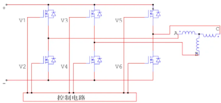
B. Rotor Position Detecting with No-position Sensor The rotor detecting ways with no-position sensor is counter potential, follow current am bipolar method, inductance method and state observer method. The principle of counter potential method is ignore the armature reaction of influence of Permanent Magnet Brushless DC Motor, via detect the counter potential of cut phase cross zero, to obtain six important rotor position sensor in turn, and hereby as the reference basis, alternate trigger break over six power tube. From Fig. 3 and Fig. 4, it’s known that, at the any time of inerter supplying power, one phase of upper and lower control arms always stay off state, that this phase of motor is impending, as the result, this phase winding voltage equate induced voltage. Detecting the time of counter potential cross zero, and delaying suitably, we can obtain the power device correct trigger time, and
counter potential cross zero can be detected by phase voltage and terminal voltage[3,4,5,6].
Figure 3. BLDC motor three phase main circuits.
Figure 4. The Back EMF wave of motor
IV. E LECTRIC A IR - CONDITION S ENSORLESS D RIVE R EALIZATION
PMSM as no Rectifier electric motor, has mature technique, well reliability, no maintained, for this reason, is widely used in electric vehicle. The article regards extensive representative PMSM as the object of study, and mathematic model direct to PMSM. At the basis of this, the article introduce the vector control arithmetic-Field Oriented Control.
A. PMSM Mathematic Molding
PMSM model based on d q − whirl coordinate.
Voltage circuit equation based on two phase rest frame:
sin cos
S
e f S
U R pL i
U R pL i
α α
β β
ω ψ θ θ
⎡ ⎤ ⎡ + ⎤ ⎡ ⎤ ⎡ − ⎤
= +
⎢ ⎥ ⎢ ⎣ + ⎥ ⎦ ⎢ ⎥ ⎢ ⎣ ⎥ ⎦
⎣ ⎦ ⎣ ⎦ (1)
As in (1), its known that still exist rotor position degree θ in model, and difficult to analyze and calculate, as a result we must realize decoupling transformation to rotor position degree.
The transformation formula from steady two phase α β − coordinate to d q − rotational coordinates is:
1
0 0
cos sin 0 cos sin 0
sin cos 0 sin cos 0
0 0 1 0 0 1
d
q Park park Park
f f
f T f T T
f f
α β
θ θ θ θ
θ θ
−θ θ
⎡ ⎤ ⎡ ⎤ ⎡ ⎤ ⎡ − ⎤
⎢ ⎥ = ⎢ ⎥ = − ⎢ ⎥ = ⎢ ⎥
⎢ ⎥ ⎢ ⎥ ⎢ ⎥ ⎢ ⎥
⎢ ⎥ ⎢ ⎥ ⎣ ⎦ ⎢ ⎣ ⎥ ⎦ ⎢ ⎣ ⎥ ⎦
⎣ ⎦ (2)
PEDS2009
1600
As in (2) voltage equation based on d q − rotational coordinates which comes from transformation formula:
0 0
0 1
d d d d
S e f
q q d q