1
Laser Welding of a Near-Beta Titanium Alloy Ti-5Al-5V-5Mo-3Cr
By
Tasneem Shariff
A Thesis Submitted to the Faculty of Graduate Studies and Research in Partial Fulfillment of the Requirements for the Degree of Master of Engineering
Department of Mining and Materials Engineering
McGill University Montreal, Canada
August, 2010
978-0-494-74994-4 Your file Votre référence
Library and Archives
Canada Bibliothèque et
Archives Canada Published Heritage
Branch
395 Wellington Street Ottawa ON K1A 0N4 Canada
Direction du
Patrimoine de l'édition 395, rue Wellington Ottawa ON K1A 0N4 Canada
NOTICE:
ISBN:
Our file Notre référence 978-0-494-74994-4 ISBN:
The author has granted a non-
exclusive license allowing Library and Archives Canada to reproduce, publish, archive, preserve, conserve, communicate to the public by
telecommunication or on the Internet, loan, distrbute and sell theses
worldwide, for commercial or non- commercial purposes, in microform, paper, electronic and/or any other formats.
The author retains copyright ownership and moral rights in this thesis. Neither the thesis nor substantial extracts from it may be printed or otherwise reproduced without the author's permission.
In compliance with the Canadian Privacy Act some supporting forms may have been removed from this thesis.
While these forms may be included in the document page count, their removal does not represent any loss of content from the thesis.
AVIS:
L'auteur a accordé une licence non exclusive permettant à la Bibliothèque et Archives Canada de reproduire, publier, archiver, sauvegarder, conserver, transmettre au public par télécommunication ou par l'Internet, prêter, distribuer et vendre des thèses partout dans le monde, à des fins commerciales ou autres, sur support microforme, papier, électronique et/ou autres formats.
L'auteur conserve la propriété du droit d'auteur et des droits moraux qui protege cette thèse. Ni la thèse ni des extraits substantiels de celle-ci ne doivent être imprimés ou autrement
reproduits sans son autorisation.
Conformément à la loi canadienne sur la protection de la vie privée, quelques formulaires secondaires ont été enlevés de cette thèse.
Bien que ces formulaires aient inclus dans la pagination, il n'y aura aucun contenu manquant.
2 Dedicated to my parents,
Sadique and Maqsuda Shariff
3
Abstract
Titanium alloys are widely used in the aerospace industry due to their high specific strength and excellent corrosion resistance. However, for some large scale aircrafts, such as Airbus A380 and Boeing 787, there is a demand for even stronger Ti alloys for structural and load bearing applications. Ti-5Al-5V-5Mo-3Cr (Ti-5553) is a new metastable β titanium alloy that exhibits excellent strength characteristics, even higher than the currently used α-β titanium grades, such as the workhorse Ti-6Al-4V alloy. It is expected that Ti-5553 will gain wider applications in the future and hence its weldability needs to be addressed. The current work is aimed at investigating the laser weldability of Ti-5553. Autogenous welds were produced by varying the defocusing distance and weld speed. The weld quality was investigated in terms of the surface morphology, welding defects, microstructure, hardness, and tensile properties. It was determined that welds with full penetration could be achieved and defects could be maintaned to meet aerospace specification tolerances by carefully manipulating the defocusing distance and weld speed within an optimum processing window. Welding was also conducted with Ti-6Al- 4V filler wire and the effect of varying joint gaps was investigated on the metallurgical and tensile properies of Ti-5553 laser welds. It was found that welds with full penetration could be produced upto a gap of 0.5 mm for 3.1 mm thick plates. Increasing the joint gap, and hence the amount of filler wire resulted in the presence of martensite which was due to the incomplete and nonuniform mixing of base material and filler wire.
4 Résumé
Les alliages de titan sont beaucoup utilises dans l’industrie aérospatiale à cause de leurs caractéristiques de haute dureté et de la résistance à la corrosion. Néanmoins, pour les avions de grande taille, tels que Airbus A380 et Boeing 787, une dureté plus haute est requise dans les applications de support structurel. Ti-5Al-5V-5Mo-3Cr (Ti-5553) est une nouvelle alliage de titan fait de β métastable qui démontre les caractéristiques de dureté qui sont supérieurs à d’autres alliages de α-β de titan qui sont utilisées présentement, en incluant l’alliage de Ti-6Al-4V. Il est attendu que l’utilisation de l’alliage de Ti-5553 se répandra dans l’avenir, pour cela, la question de soudage de ce matériel doit être adressée. Le travail actuel recherche l’habilité de soudage à laser de Ti-5553. Les autogènes soudures ont étés produites en changeant la distance du centre d’intérêt et en variant la vitesse de soudage. La qualité des soudures a été analysée selon l’anatomie de la surface, des défauts de soudage, de la microstructure, de la dureté et des propriétés de traction. Il a été détermine qu’on peut obtenir les soudures de pleine pénétration et qu’on peut atteindre les spécifications aérospatiales de tolérance des défauts en contrôlant soigneusement la distance du centre d’intérêt ainsi que la vitesse de soudage dans une fenêtre de processus optimisée. Le soudage a aussi été conduit avec fil languette de Ti- 6Al-4V et l’effet de variation de l’espace entre les jonctions sures les propriétés de traction et sure métallurgie de soudures de Ti-5553 a été investiguée. Il a été constaté qu’on peut obtenir les soudures de pleine pénétration jusqu’une espèce entre les jonctions de 0.5 mm pour les plaques d’épaisseur de 3.1mm. La présence de martensite a été constatée pour une distance entre les jonctions plus grand ayant plus de quantité de fil languette. Martensite s’est formée à cause d’un mélange non uniforme et incomplet entre le matériel de base et celui du fil languette.
5 Acknowledgements
First and foremost, with sincere appreciation and gratitude, I would like to thank my supervisors Dr. Xinjin Cao and Professor Richard Chromik for their unwavering support and optimism throughout this Master’s degree. There generous guidance and critical suggestions have been a key factor towards the success of this project as it stands. I would also like to thank the National Research Council of Canada and Standard Aero Inc.
for their funding, without which the project would not have been able to proceed.
I would also like to thank Dr. Priti Wanjara, Dr. Javed Gholipour, E. Poirier, D. Chiriac, and M. Anderson at the National Research Council of Canada for their insight and technical support in performing the laser welding and mechanical testing with the ARAMIS system as well as my best friend Dina Goldbaum for helping me with nanoindentation experiments. I would also like to acknowledge my group mates, Pantcho Stoyanov and Holger Strauss for their precious help, thoughts, and suggestions.
Finally, I would like to extend my appreciation to my family, Sadique, Maqsuda, Faisal, Sajjid, Sobia, and Nishi Shariff as well as my soul mate Imran Shariff without whose help, support, and encouragement I would not have been able to pursue my dreams. I hope they understand the depth of their contribution.
6 Preface
This is a manuscript-based thesis that contains five chapters. The second chapter presents background information and a literature review on titanium alloys with particular emphasis on near-beta titanium alloys as well as the fundamental aspects of laser welding. In Chapter 3, autogenous welds are produced by varying the defocusing distance and weld speed and the as-welded quality is investigated in terms of surface morphology, joint geometry, microstructure, defects, and mechanical properties with the objective of producing welds to meet aerospace specification tolerances. In Chapter 4, defocusing distance, welding speed, and power are kept constant and welding is conducted with Ti-6Al-4V filler wire by varying the joint gap. By implementing the joint gap, it is hoped that the tight joint fit-up requirement required for laser welding can be reduced, as well as reducing the presence of underfill which has a negative impact on the mechanical properties. However, introducing filler wire into the system can cause a modification of the fusion zone composition which may lead to a different microstructure than that observed during autogenous welding and hence a variation in properties.
Finally, the last chapter presents a summary of the current work and makes suggestions for future work.
Contribution of Authors
The author of this thesis, is the primary author for all the papers included in this thesis.
Dr. Xinjin Cao from the National Research Council of Canada as well as Professor Richard Chromik from McGill University are my supervisors and are included in the list of co-authors. Dr. Priti Wanjara and Dr. Javed Gholipour from AMTC-IAR are also co-
7 authors and are recognized for their helpful insight and aid in performing the mechanical testing experiments with ARAMIS. J. Cuddy, and A. Birur from StandardAero are recognized and listed as co-authors for providing the funding and materials necessary to carry out this project. The two papers that form chapter 3 and chapter 4 are listed below:
T. Shariff, X. Cao, R.R. Chromik, J. Gholipour Baradari, P. Wanjara, J. Cuddy, and A.
Birur, “Effect of Defocusing Distance and Weld Speed on Laser Welding of Ti-5553”, COM 2010, Paper No. 5529, Vancouver, BC, Canada.
T. Shariff, X. Cao, R.R. Chromik, J. Cuddy and A. Birur, “Effect of Joint Gap on the Quality of Laser Welded Ti-5553. Part I. Metallurgical Aspects”, to be submitted.
8 Table of Contents
ABSTRACT ... 3
RÉSUMÉ ... 4
ACKNOWLEDGEMENTS ... 5
PREFACE... 6
TABLE OF CONTENTS ... 8
LIST OF FIGURES... 10
LIST OF TABLES ... 13
CHAPTER 1. INTRODUCTION ... 14
CHAPTER 2. BACKGROUND & LITERATURE REVIEW ... 16
2.1.BACKGROUND ON TITANIUM ALLOYS ... 16
2.1.1. Characteristics of Titanium as Applied to the Aerospace Industry ... 16
2.1.2. Classification of Titanium alloys ... 17
2.1.3. Beta Titanium Alloys. ... 20
2.2.BACKGROUND ON LASER WELDING ... 23
2.2.1. Process Mechanism ... 24
2.2.2. Lasers in Welding ... 31
2.2.3. Parameters that Influence the Weld ... 32
2.3.LITERATURE REVIEW... 44
2.3.1. History of Beta Alloys and current Applications ... 44
2.3.2. Comparison of Ti-5Al-5V-5Mo-3Cr with Ti-6Al-4V ... 46
2.3.3. Strengthening mechanisms and microstructures in Ti-5553 alloys ... 48
2.3.4 Weld Defects in Titanium Alloys ... 53
2.3.5. Studying the mechanical properties of weldments ... 59
2.2.6. Summary ... 60
CHAPTER 3. EFFECT OF DEFOCUSING DISTANCE AND WELD SPEED ON LASER WELDING OF TI-5553 ... 61
3.1.INTRODUCTION ... 61
3.2.EXPERIMENTAL PROCEDURE ... 61
3.3.RESULTS AND DISCUSSION... 64
3.3.1. Joint Morphology and Shape ... 64
3.3.2. Defects ... 68
3.3.3. Microstructure ... 72
9
3.3.4. Hardness ... 76
3.3.5. Tensile Properties ... 77
3.4.CONCLUSIONS ... 81
CHAPTER 4. EFFECT OF JOINT GAP ON THE QUALITY OF LASER WELDED TI-5553. PART I. METALLURGICAL ASPECTS ... 82
4.1.INTRODUCTION ... 82
4.2.EXPERIMENTAL PROCEDURES ... 82
4.3.RESULTS AND DISCUSSION... 84
4.3.1. Weld Beads ... 84
4.3.2. Defects ... 87
4.3.3. Microstructure ... 92
4.3.4. Hardness ... 98
4.4.CONCLUSIONS ... 101
CHAPTER 5. SUMMARY ... 102
REFERENCES ... 104
10 List of Figures
Figure 1. The two allotropic forms of titanium (a) HCP and (b) BCC β phase ... 17
Figure 2. Influence of alloying elements on titanium alloys and their phase diagrams ... 18
Figure 3. 3D phase diagram showing the three classes of titanium alloys ... 19
Figure 4. Comparison of Mo. Eq. values for various titanium alloys ... 22
Figure 5. Schematic view of melt pool during (a) conduction welding and (b) keyhole welding ... 25
Figure 6. Power vs. welding speed for 1 mm and 3 mm thick Ti-6Al-4V sheets ... 33
Figure 7. Characteristics of a focused laser beam ... 34
Figure 8. The effect of focus position of the laser beam on the work surface ... 35
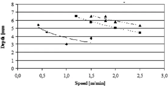
Figure 9. Variation of weld bead depth for Ti-6Al-4V ... 37
Figure 10. Illustrations of weld defects (a) undercut and (b) underfill ... 37
Figure 11. Melting depth vs. welding speed for He and Ar at 1500 W for Ti-6Al-4V ... 39
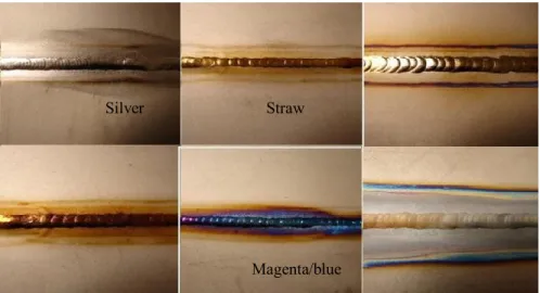
Figure 12. Discolorations during welding of titanium arising from contamination ... 40
Figure 13. Geometry of leading edge filler wire laser welding ... 42
Figure 14. Selection of joint designs and weld bead shapes for laser welding... 44
Figure 15. SR-71A in flight over Southern Sierra Nevada Mountains ... 45
Figure 16. High cycle fatigue behaviour for Ti-5553 and Ti-6Al-4V ... 48
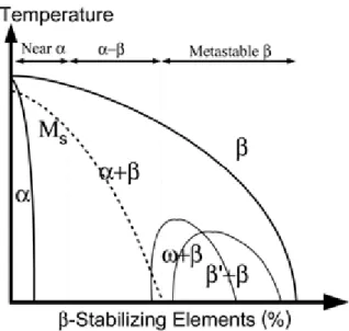
Figure 17. Schematic for a binary phase diagram for Ti alloys ... 49
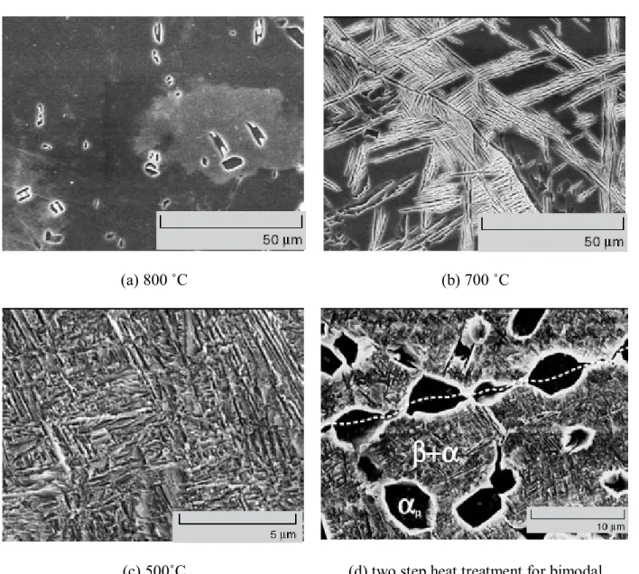
Figure 18. Scanning electron micrographs of microstructures resulting from various ageing temperatures for Ti-5553 ... 51
Figure 19. (a) microhardness and (b) tensile properties of Ti-5553 alloy as a function of ageing temperature ... 52
Figure 20. Microstructure of Timetal Beta-21S alloy (a) mill-annealed condition and (b) ageing at 538˚C for 8 hr ... 56
11 Figure 21. Dissimilar welds between Ti-6Al-4V and Ti-15V-3Cr-3Al-3Sn sheets showing
martensitically transformed solute bands (small arrows) for (a) light optical
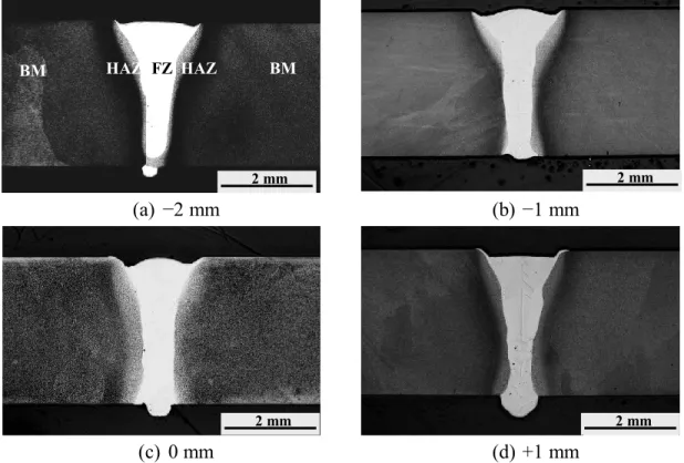
microscope and (b) SEM ... 58 Figure 22. Stereoscopic micrographs showing the crown and root surface morphologies at defocusing distances a) −2 mm and b) +1 mm at 6.0 m/min. The welding direction is from left to right. ... 65 Figure 23. Effect of defocusing distance on the cross sections at 6.0 m/min. ... 66 Figure 24. Effect of defocusing distance on the FZ and HAZ areas and widths at 6.0
m/min. ... 66 Figure 25. Effect of weld speed on the transverse sections at −1 mm defocusing. ... 67 Figure 26. Effect of weld speed on FZ and HAZ areas and widths at defocusing distance
of −1 mm. ... 68 Figure 27. Effect of (a) defocusing distance and (b) weld speed on the maximum underfill depth. ... 70 Figure 28. Various types of porosities in the welds (a-c) gas porosity near FZ/HAZ
interface, (d) cluster of porosity near the bottom of weld and (e, f) shrinkage porosity.
... 71 Figure 29. Effect of welding speed on the total porosity area and % porosity in the FZ. . 72 Figure 30. Series of optical micrographs from the BM to the end of the HAZ for a
welding speed of 2.25 m/min and defocusing distance of −1 mm ... 74 Figure 31. Volume percentage and particle diameter of primary α across the welded joint
... 75 Figure 32. Typical microstructures of (a) the FZ/HAZ boundary and (b) the FZ for a
welding speed of 2.25 m/min and a defocusing distance of −1 mm... 75 Figure 33. Effect of defocusing distance at −2 and +1 mm on the FZ microstructure ... 75 Figure 34. Microindentation hardness profiles at (a) 3.0 m/min) and (b) 2.25 and 6.0
m/min (top profile) ... 76 Figure 35. Effect of weld speed on the UTS, YS, and Elongation at a defocusing distance
of −1 mm ... 79 Figure 36. Fracture locations for welds at (a) 2.25 m/min and (b) 6.0 m/min ... 79
12 Figure 37. Secondary electron images indicating (a) shallow ductile dimples and (b)
porosity ... 80 Figure 38. Distribution of strain across the weld joint prior to failure at (a) 2.25 and (b)
6.0 m/min ... 80 Figure 39. Effect of joint gap on transverse sections of 3.1 mm thick joints ... 86 Figure 40. Effect of joint gap on the (a) FZ and total HAZ areas and (b) FZ widths ... 87 Figure 41. Porosity located in the fusion zone at joint gaps of (a) 0.2 mm and (b) 0.3 mm
... 89 Figure 42. Effect of joint gap on (a) porosity and (b) underfill area ... 90 Figure 43. Optical (left) and SEM (right) micrographs of the base material showing
bimodal α morphologies in a β matrix ... 92 Figure 44. Overview of microstructures for 0 mm joint gap (no filler wire added) (a)
transverse section, (b) heat affected zone/fusion zone, and (c) fusion zone ... 94 Figure 45. Series of optical micrographs at various locations in the HAZ for a weld
obtained at a welding speed of 2.25 m/min and defocusing distance of −1 mm ... 94 Figure 46. Effect of joint gap on the microstructure in the fusion zone ... 96 Figure 47. High magnification optical images showing the regions of martensite and
retained β at joint gaps ranging from 0.3 to 0.5 mm. ... 97 Figure 48. Influence of joint gap on the amount of martensite observed in the fusion zone
with respect to the quantity of the filler wire added. ... 97 Figure 49. Hardness profile across the weld at 0.1 mm joint gap ... 100 Figure 50. Effect of joint gap on the fusion zone hardness ... 100
13 List of Tables
Table 1. Properties of α, α + β and β titanium alloys ... 20
Table 2. General Advantages and Disadvantages of Beta Alloys ... 22
Table 3. Various dimensionless groups describing relative importance of process mechanisms ... 29
Table 4. Mechanical properties of Ti-5553 versus Ti-6Al-4V ... 47
Table 5. Processing parameters used for Ti-5553 ... 64
Table 6. Average porosity size determined by radiography ... 89
14 Chapter 1. Introduction
Titanium alloys offer a combination of excellent properties, and the two that stand out the most is their high specific strength and good corrosion resistance 1. As a result, titanium alloys have been particularly attractive to the aerospace industry since it is under continual pressure to reduce operating cost through lower weight and less maintenance 2. It has been reported that titanium based alloys in Airbus aircraft has risen from 5% by weight for earlier models to almost 10% in the Airbus A380 3. The Boeing 777 airframe uses approximately 10% titanium alloys out of which the high strength β alloy Ti-10V- 2Fe-3Al (Ti-10-2-3) has outweighed the most commonly used α/β alloy Ti-6Al-4V 1.
In recent years, both Boeing and Airbus have announced that Ti-10-2-3 will be replaced by another near-β alloy Ti-5Al-5V-5Mo-3Cr (Ti-5553) for landing gear assemblies 4. Ti- 5553, a variation of the Russian alloy VT22 5, is a heat-treatable titanium alloy that is characterized by a high strength (~1250 MPa at room temperature for certain microstructures) and high cycle fatigue properties compared to Ti-6Al-4V 6. It is also applicable for thick sections due to its deep hardenability and also offers a wider processing window than Ti-10-2-3 4, 7. Therefore, it is expected that Ti-5553 will gain wider acceptance in the near future and hence its weldability must be addressed. Laser welding has been developed and processing parameters have been identified producing repeatable and high-quality welds for Ti-6Al-4V components2. To date, very little has been reported on the weldability of Ti-5553.
15 The present work focuses on the welding of the relatively new near-beta titanium alloy, Ti-5553, which is still in its early stages of development. The primary objective of this project is to assess the weldability of Ti-5553, since very little information has been reported to date. This will be accomplished by the laser welding technique which has been utilized in this work to produce aerospace quality welds. The layout of this thesis has been divided into two main sections which consist of (1) the optimization of fundamental laser welding parameters such as defocusing distance and weld speed to produce welds within aerospace tolerance and (2) effect of assigning joint gaps when welding with Ti-6Al-4V filler wire.
16 Chapter 2. Background & Literature Review
2.1. Background on Titanium Alloys
2.1.1. Characteristics of Titanium as Applied to the Aerospace Industry
William Gregor discovered titanium in 1791 but it wasn’t until 1932 that Wilhelm Justin Kroll was able to produce isolated titanium in large quantities by combining TiCl4 with calcium. Moreover, it is not as rare of a substance as many would initially believe. It ranks in the fourth position as the most common structural metal exceeded by aluminum, iron and magnesium 8.
Titanium has a number of desirable properties for aerospace applications and the two that stand out the most in comparison to other materials is their high specific strength and excellent corrosion resistance. Carbon fiber reinforced plastics (cfrp) have a higher specific strength than titanium alloys but only at temperatures less than 300 ˚C 8. The specific strength of titanium becomes particularly attractive when operating temperatures are moderately high 8. The maximum application temperature is limited by their oxidation behaviour since titanium tends to react with atmospheric elements such as oxygen, nitrogen, and hydrogen at high temperatures resulting in an increase in strength but decrease in ductility.
Another advantage of titanium is that it undergoes an allotropic transformation at approximately 882 C from a HCP (α) phase to a BCC (β) phase which are shown in Figure 1 9. The existence of these two different crystal structures and their transformation is of great importance since it offers the prospect of having alloys with alpha, beta, or
17 mixed alpha/beta microstructures leading to a wide range of properties 9. The possibility of heat treatment further extends the range of microconstituents that may be formed 9.
A combination of specific strength, heat resistance, corrosion resistance, microstructural tailoring and other positive properties allow titanium to be considered for a diverse range of applications which include biomaterials, power generation, ship building, etc. Most importantly, however, the largest consumer of titanium alloys has been the aerospace industry in which titanium alloys have been applied as airframe and engine materials 7.
(a) (b)
Figure 1. The two allotropic forms of titanium (a) HCP and (b) BCC β phase 8
2.1.2. Classification of Titanium alloys
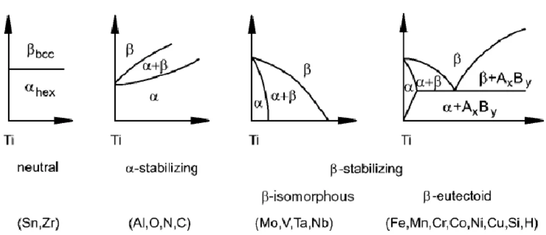
Titanium can form solid solutions with most substitutional elements and can also react strongly with interstitial elements such as oxygen, nitrogen, and hydrogen 10. Depending on their influence on the β- transus temperature, the alloying elements of titanium are classified as either neutral, α-stabilizers, or β-stabilizers as seen in Figure 2 8. The α-
18 stabilizers are elements that dissolve preferentially in the α-phase and raise the α/ β transus, thereby expanding the α field 8-10. Among the α-stabilizers, aluminum is the most important alloying element 8. The interstitial elements oxygen, nitrogen and carbon also belong in this category 8. Elements which depress the α/ β transus and stabilize the β phase are subdivided into β-isomorphous and β-eutectic elements 8-9. It has been reported that the eutectoid reactions in a number of alloys are so sluggish that in practice, the alloys behave as though the reaction did not occur 9.
Figure 2. Influence of alloying elements on titanium alloys and their phase diagrams 8
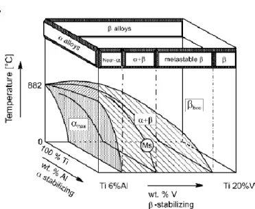
Titanium alloys are classified into three main groups designated α, α+β, and β alloys, with further subdivisions into near-α and metastable β alloys as schematically shown in Figure 3 8-10. The α-alloys comprise of commercially pure (cp) titanium and alloys exclusively alloyed with α-stabilizers and/or neutral elements. If small fractions of β- stabilizing elements are present, the alloy is called a near-α alloy. The α+β group, which is the most widely used alloy group, has a β volume fraction from about 5 to 40 %.
Metastable β titanium alloys, which will form the basis for this research, are those that contain enough β-stabilizing elements to surpass the martensite start temperature upon
19 quenching and yet are still in the two-phase field. It should be noted that these alloys can still reveal an equilibrium α volume fraction of more than 50 % upon ageing. Finally, the single phase β alloys mark the end of the alloying scale for conventional titanium alloys 8-
10.
Figure 3. 3D phase diagram showing the three classes of titanium alloys 8
The essential differences in the properties between the three alloy classes are qualitatively summarized in Table 1. The HCP α phase is more densely packed and has an anisotropic crystal structure 8. Compared with the β-phase, α has a higher resistance to plastic deformation, reduced ductility, a lower diffusion rate, and higher creep resistance. In comparison, α-alloys only have moderate strength whereas α+β and the metastable β alloys can be hardened to high and very high strength levels respectively 8.
20 Table 1. Properties of α, α + β and β titanium alloys
2.1.3. Beta Titanium Alloys.
As mentioned earlier, β-titanium alloys are defined as alloys that retain an all beta structure upon quenching from the beta phase field 9. These alloys contain enough beta stabilizing elements to avoid cooling through the martensite start line consequently avoiding the formation of martensite. Alloys that lie between this critical limit (βc) and the intersection point of the beta transus line as indicated in Fig.3 are termed metastable beta titanium alloys since they can precipitate a second phase, most often the alpha, upon heat treatment9. This gives added benefits of both processing and strengthening since it is thus possible to retain the more ductile BCC phase in a metastable state for easy forming after which the alloy can be strengthened by aging. This is the main reason why metastable beta titanium alloys such as Ti-5Al-5V-5Mo-3Cr have attracted so much attention in the past decade.
The overall beta stability for an alloy with various alloying additions can be conveniently expressed as a molybdenum equivalent which is defined as follows 9, 11:
21 )
(%
0 . 1 ...
) (%
6 . 1 ) (%
9 . 2 ) (%
22 . 0
) (%
28 . 0 ) (%
44 . 0 ) (%
67 . 0 ) (%
0 . 1 .
Al Cr
Fe Ta
Nb W
V Mo
Eq
Mo Equation 1
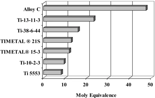
In the above equation (all elements in wt. %), the constant before each alloying element reflects the ratio of the βc for molybdenum divided by βc for the particular element 9, 11. The aluminum is subtracted from the overall equation to reflect the opposite effect of this element in stabilizing the alpha phase. In general, a Mo. Eq of approximately 10.0 is required to stabilize beta upon quenching and retain 100% beta upon quenching.
However, it is not clear what Mo. Eq. is required to produce a truly stable beta alloy 9, 11. Figure 4 shows a comparison of the calculated Mo. Eq values for various alloys. Note that Ti-10V-2Fe-3Al (Ti-10-2-3) and Ti-5Al-5V-5Mo-3Cr are very marginal in terms of stability. Beta titanium alloys are a versatile class of alloys with respect to processing, microstructure, and mechanical properties. Table 2 qualitatively compares the advantages and disadvantages of beta alloys.
These alloys, compared to the other classes discussed in the previous section, offer the highest strength to weight ratio although they are higher in density compared to the other alloys. Beta titanium alloys attracted early attention because of superior forming characteristics anticipated form their BCC crystal structure. Moreover, they offer the prospect of being cold formed in a relative soft condition and then strengthened by age- hardening 9. Other advantages include increased heat treatability, deep hardening potential, and inherent ductility, as well as outstanding corrosion resistance. It has been noted that corrosion resistance generally increases with molybdenum content 9, 11.
22
0 10 20 30 40 50
Moly Equivalence Ti 5553
Ti-10-2-3 TIMETAL® 15-3 TIMETAL ® 21S Ti-38-6-44 Ti-13-11-3 Alloy C
Figure 4. Comparison of Mo. Eq. values for various titanium alloys
Table 2. General Advantages and Disadvantages of Beta Alloys 11
Advantages Disadvantages
- High specific strength - Low modulus
- Strip producible - Easy to heat treat
- Some have good castability - Excellent corrosion properties for
some compositions
- High density - Low modulus
- High formulation cost - Oxygen hydrogen pick up - Segregation
23 2.2. Background on Laser Welding
Fusion welding of metals and alloys is used in a wide variety of applications such as the construction of buildings and bridges, automotives, aerospace, electronic, chemical, and power generation industries 12. It is important that the selection of a weld technique carefully consider reliability, maintainability, and safety together with the highest performance/integrity and overall lowest cost.
Fusion welding involves the melting and solidification of adjacent areas of two components. A number of fusion welding processes exist, each defined by the nature of their heat source. For example, an electric arc is used in gas-tungsten and gas metal arc welding, whereas very high-energy density beams are used as energy sources in electron beam and laser welding 12. In fact, the focussed laser beam has one of the highest power densities available in industry today that is in excess of 104 W/mm2 13. At such a high power density, all materials are evaporated if the energy can be absorbed creating a hole that is then traversed through the material with the molten walls sealing up behind it. A special name exists for welds of this type and it is generally termed keyhole welding 14.
Laser welding in the keyhole mode has many advantages including a low and precise heat input which ultimately results in less thermal distortion and greater accuracy. It is characterized by a small heat affected zone and a deep and narrow fusion zone with aspect ratios (depth/width) commonly around 4:1 but can be as high as 10:1 15. Laser welding is a highly productive process resulting from its high welding speeds and from the ability to easily be automated. It offers good process flexibility as well as reliability
24 and offers the potential to weld a wide range of materials such as steel, Al, Ti, Mg, and superalloys as well as dissimilar materials. Unlike electron beam welding which requires a vacuum chamber for welding, laser beam welding can be performed in various environments such as vacuum, air, pressurized chambers or controlled atmospheres and in some locations that are normally inaccessible or accessible only from one side.
Furthermore, laser beams are not affected by magnetic fields as electron beams normally are.
As in all welding processes, a number of shortcomings exist that limit the applicability of laser welding. One of the major disadvantages of laser welding is the high equipment and operating costs that is justified only when mass scale production is required. Other disadvantages include stringent requirements for the clamping and fitting of work-pieces, requirement for accurate beam and joint alignment, and finally the strict safety requirement with respect to robotic manipulation and eye protection 16-17. It is important to realise that the cost penalty is offset by the productivity, product quality, and process flexibility.
2.2.1. Process Mechanism
The Keyhole:
It is understood that two modes exist during laser welding and these are known as either the conduction or keyhole mode as illustrated in Figure 5 18. During conduction welding, the power density is insufficient to initiate vaporization from the material surface and so the surface of the weld pool remains unbroken. These types of welds are typically characterized by an aspect ratio that is less than one (penetration depth is smaller than the
25 weld bead width) 18. In contrast to the conduction mode of welding, there is a sufficient power density during keyhole welding to cause evaporation in the melt pool ultimately resulting in the formation of a capillary tube surrounded by molten metal. The subsequent ionization of the vapour results in the formation of the plasma. This region of molten metal flows around the keyhole as the work-piece and the laser beam move relative to each other and solidifies to give a characteristic chevron pattern 12-13. The typical range of power density that creates the keyhole is from 103 to 105 Wmm-2 19. Above this range, welding is impractical and cutting and drilling is usually achieved.The keyhole plays an important role in transferring and distributing the laser energy to provide deep penetration as will be seen later.
Figure 5. Schematic view of melt pool during (a) conduction welding and (b) keyhole welding 18
The stability of the keyhole depends on a force balance between the recoil force of vaporization and the surface tension pressure 20. As the vapour pressure acts to keep the keyhole open, the surface tension will tend to close it 13, 21. The requirement to maintain
26 this balance for keyhole stability leads to practical minimum and maximum traversing rates for keyhole welding 13, 22.
Once the keyhole has formed, it begins to behave as an optical black body in which two absorption mechanisms are dominant. These are defined as Fresnel absorption and Inverse Bremsstrahlung absorption 14, 23. It is the sum of these two energy absorption processes that is responsible for the overall energy transfer efficiency. Fresnel absorption corresponds to the direct interaction of the beam with the material and can be divided into the first Fresnel absorption and multiple internal reflections 14, 23. Inverse bremsstrahlung absorption which defines the transfer of energy from photons to electrons takes place in the partially ionized plasma formed in and above the keyhole. It is important to understand that the plasma facilitates the energy transfer from the beam to the material, but it also acts to defocus the laser beam and reduce its power density. It is thought that plasma absorption dominates at slow speeds and the beam is absorbed by inverse bremsstrahlung effects in the keyhole. As the speed increases the Fresnel absorption gains importance due to the cooler plasma being less absorbed 14.
Energy absorption during welding is an important physical process to understand since it is responsible for the final outcome of the welding process. The absorbed energy will consequently have an affect on the formation of the liquid pool, as well as the time- dependant temperature field in the weld and ultimately the structure and properties of the joint 12. Not all of the energy supplied by the heat source is absorbed by the workpiece.
Several factors influence the energy absorbed by the work-piece and these are unique to
27 each welding process 12. During laser welding, the absorption of the laser beam is affected by the wavelength of the laser, the nature of the surface, joint geometry, and the nature of the plasma present above the weld pool 12.
Fluid Flow and Heat Transfer
Once the material and the laser beam are coupled, their interaction leads to rapid heating, melting, and a flow of molten material which is driven by buoyancy, surface tension, impingement, or friction 12. The two physical processes of heat transfer and fluid flow are important since they ultimately affect the evolution of the weldment structure and properties. To be more specific, the size and shape of the weld pool, as well as the cooling rates and kinetics/extent of the subsequent solid-state reactions in the fusion zone and heat affected zone are affected 12.
The flow of molten material is driven by surface tension and buoyancy. The strong stirring forces in the weld pool are driven by Marangoni type forces which result from the variation in surface tension with temperature 14. This can be expressed as the Marangoni stress:
dy dT dT
d Equation 2
where τ is the shear stress due to the temperature gradient, γ is the interfacial tension, T is temperature, and y is the distance along the surface from the axis of the heat source. In general, the coefficient of surface tension increases with a decrease in temperature. This results in surface tension gradients that drive the fluid flow from the center of the melt towards the edges 13. It should be noted that the Marangoni flow is the dominant
28 convection mechanism 13. Buoyancy effects, on the other hand, originate from the spatial variation of the liquid metal density, mainly because of temperature variations, and to a lesser extent, from local composition variations 12. It has been noted that the velocities of buoyancy driven flows in the weld pool are commonly much small than those flows that are driven by surface tension driven flows 12.
A number of dimensionless groups of processing variables are used to indicate the relative importance of process mechanisms operating during laser welding. Among these is the Peclet number, Pe, which describes the relative importance of forced convection to thermal conductivity and is given by:
k
L c
Pe u p Equation 3
where u, is the velocity, ρ is the density cp, is the specific heat at constant pressure, L is the characteristic length, and k is the thermal conductivity of the melt. When the Pe number is larger than one, the heat is primarily being transferred by convection, and heat conduction is not as important 13. It is generally thought that conditions that lead to a high Peclet number such as high traversing speeds and low thermal conductivities result in lower melt depth 13. The conductivity of heat is also very important since it drives away the heat away from the weld pool ultimately affecting the size of the molten pool 12. The other dimensionless groups which are just as important as the Peclet number are summarized and described in Table 3. Note that in the table, μ is the kinematic viscosity, and g is the gravitational force.
29 Table 3. Various dimensionless groups describing relative importance of process
mechanisms
Group Equation Processes Effects
Prandtl number (Pr) Pr k
Rate of thermal convection vs. rate of thermal
conduction
Ability to be ablated with little thermal effect on the substrate Reynolds number
(Re)
Re Lu Laminar flow vs.
turbulent flow
Turbulent flow results in rougher surface due to entrainment of atmosphere
Marangoni number
(Ma) ---
Rate of convection vs. rate of rate of conduction
Relative importance of the two heat transfer
mechanisms. Affect how wide or shallow the melt pool is Froude number
(Fr2) gL
Fr2 u2 Inertial force vs.
gravitational force
High Froude number lead to increased fluid flow. Results in surface humps in solidified material
Regions of the weld zone:
Laser welding produces three different regions which are defined according to the temperatures experienced during welding. These regions are broadly defined as the fusion zone (FZ), partially melted zone (PMZ), and heat affected zone (HAZ) 24. These regions are generally narrower for laser welding operations than other welding processes.
Compared to solidification rates on the order of 102 to 103˚C/sec, laser welding and electron beam welding can have solidification rates as high as of 105 to 106 ˚C/sec 24.
30 The fusion zone experiences temperatures above the liquidus of the alloy 13. For titanium alloys, the fusion welds are generally characterized by coarse columnar beta grains in the fusion zone (FZ) which grow epitaxially into the weld pool from coarsened semi-melted beta grains in the PMZ 25. The solid around the melt pool acts as a heat sink resulting in high temperature gradients and ultimately high cooling rates. The beta grain size is principally determined by the weld energy input, with a higher energy input promoting a coarser grain size. However, it is possible to manipulate the beta grain size by altering laser beam parameters.
An issue with beta titanium alloys is that of segregation, especially in those alloys that contain the β eutectoid elements like iron or chromium. Eutectoid beta stabilizers have a wide freezing range and tend to segregate strongly resulting in regions with significantly lower beta transus values than the bulk 11. These regions are known as beta flecks.
Usually, these solutes segregate to the last liquid to freeze 1. The solute enriched liquid can exhibit shrinkage porosity along the weld centerline or can exhibit liquation cracking due the imposed thermal stresses 1. However, the rejection of the solute atoms ahead of the solid or liquid solidification front requires adequate time for solidification. The faster the solidification rate, the greater the probability that solute atoms will be trapped within the growing solid. Hence, it is generally accepted that the segregation in laser welds is not a serious issue since the cooling rates are very high.
The partially melted zone experiences peak temperatures between the liquidus and solidus during welding. Localized melting generally occurs in this region with some
31 degree of segregation at grain boundaries. This zone is often unable to withstand stresses during solidification and weld cracking may result at the weakened grain boundaries in the PMZ 13.
The microstructure, and ultimately the mechanical properties, at a location within the HAZ is determined by solid state reactions 13, 26-27. For the case of metastable β titanium alloys, which have been precipitation hardened, dissolution of the strengthening α precipitates has been observed leading to lower hardness values than the base material (the region unaffected by heat) 13, 26-27. Usually, a post weld treatment can fully regain the strength of the base material as demonstrated by Kuroda et al 27.
2.2.2. Lasers in Welding
There are a number of commercially available lasers in industry but the two most common types of lasers are the carbon dioxide (CO2) and the Nd: YAG. Both lasers operate in the infrared region of the electromagnetic radiation spectrum 28. The CO2 laser provides its light output in the far-infrared region with an output wavelength of 10.6 microns. Although the CO2 laser will have an initial reflectance that is 80-90 % for most metals, it provides a high power output of 10 000 Watts or greater 28. In comparison, The Nd: YAG laser provides its primary light output in the near-infrared with a wavelength of 1.06 microns 28. This allows the Nd: YAG laser to have higher absorptivity which is absorbed quite well by conductive materials, although the output power is not as high as that for CO2 lasers. The shorter wavelengths of the Nd:YAG laser beam allows for transmission via fiber optic cables rather than a mirror-based delivery system like that for CO2 lasers giving the Nd:YAG lasers the added advantage of easier manipulation and
32 control 29. It has been reported that Nd:YAG laser beams tend to produce slightly larger and more stable keyholes than CO2 laser beams 30. This ability allows the Nd:YAG to work with larger gap sizes without sacrificing the weld quality. Furthmore, the higher stability of the ND:YAG laser provides a more uniform weld bead with less or no porosity 30.
Another important aspect between the two laser types and their respective wavelengths is that of plasma effects. It has been reported that there will be less absorption by the plasmas for shorter wavelengths 14. As a consequence, the temperature and viscosity of the plasma is lower allowing it to be removed from the keyhole without being disturbed.
Furthermore, the welding of volatile materials such as Mg and Al alloys have reduced porosity when welded with Nd:YAG lasers compared to CO2 lasers 14.
2.2.3. Parameters that Influence the Weld
The two main types of lasers that are commonly used for industrial applications were described above. It is important to now turn our attention to the specific laser parameters since it is these parameters that determine how the welding energy is applied to the joint.
The weld shape and depth will be determined by these parameters so they need to be carefully optimized according to what the specific application demands.
Power
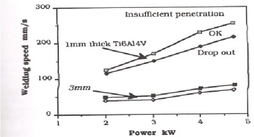
There are two main problems in welding and that is either having a lack of penetration or the opposite which is excessive melting leading to a “drop out” 14. These are the
33 boundaries for a good weld. Considering this, it is important that the laser power be set according to the thickness that needs to be welded 14. Figure 6 shows the effect of power and weld speed for 1 mm and 3 mm thick Ti-6Al-4V sheets. If we consider a given thickness, the maximum processing speed rises with increasing power. Furthermore, it can be observed that the operating window has been enlarged for greater powers 14. It is also important to note that a high-power density at the workpiece is crucial to achieve and maintain the keyhole mode of welding. This can generally be as high as 104 W/mm-2. Too high of a power density, however, can result in spatter, undercut, underfill and dropout. It is thus necessary to find the optimal setting for power density.
Figure 6. Power vs. welding speed for 1 mm and 3 mm thick Ti-6Al-4V sheets 14
Spot Size
Light that is focused by a lens will converge to a very small waist diameter, d, before it diverges again as seen in Figure 7. It is this convergence that determines the spot size 19. A combination of spot size and power determines the power density of the laser. If the power is kept constant and the spot size is reduced (by changing the focal length), the power density is increased. It is important to note that a small spot size with a high power
34 density does not necessarily mean that welding is improved 19. For example, a small spot size means that joint fit-up and beam alignment are more critical, especially since we need to pay special attention to the gap size. Furthermore, a smaller spot size and thus a higher power density leads to the evaporation of the weld metal resulting in undercuts and underfills 19.
Figure 7. Characteristics of a focused laser beam
Defocusing Distance
The defocusing distance defines the position of the focal spot, or minimum spot diameter, with respect to the surface of the workpiece. It is this distance that allows us to control the power density on the surface of the workpiece to establish the keyhole 19. Typically, this defocus distance is set to the position in which maximum penetration depth is achieved. This is schematically illustrated in Figure 8.
35 Figure 8. The effect of focus position of the laser beam on the work surface
There has been a lot of discussion on whether the defocus should be at the surface or below the surface for maximum penetration depth when making autogenous welds (those made without the addition of filler materials) 19. Several studies have shown that an increase in penetration depth is seen when focusing slightly below the surface of the workpiece. Although the mechanism for this remains unclear, it is generally believed that this is due to the enhancement in multiple internal reflections. Furthermore, It has been noted that the threshold power density for keyhole formation is lower at negative defocusing distance than at positive defocusing distance. Therefore, for the same power and spot size, it can be expected that the weld pool size is larger.
Operational Mode
There are two modes of operation during laser welding and these are known as either continuous wave or pulsed wave. Titanium can be welded in both of these modes 31. During the pulsed mode of operation, a small molten pool is formed by each laser pulse and within a few milliseconds it re-solidifies31. In other words, the keyhole has to reform
36 at the start of each pulse during pulsed laser welding and multiple internal reflection does not occur until the keyhole is reformed and deepened. Continuous laser welding (CW) is used for high speed welding, whereas pulsed welding is used for precision welding.
Weld Speed
The weld speed is determined by the material, its thickness, and laser power. Penetration depth is inversely proportional to the speed for a given defocusing distance and power thus an increase in weld speed at constant laser power will result in a decrease in penetration depth as seen in Figure 9 32. This can be explained by considering the heat input. A combination of power and weld speed determines the heat input into the work- piece (heat input = power/weld speed). If the power is kept constant, the interaction time between the laser beam and the work-piece, as well as the heat input, is reduced as the weld speed rises. This results in less material being melted and consequently less penetration is achieved.
The weld speed will also have an effect on the weld bead shape. At slow weld speeds, the weld pool is large and wide and this may result in drop out. At high speeds, undercuts may result due to the strong flows towards the centre of the weld. Since there is no time to redistribute, it is frozen as an undercut at the sides of the weld 14.
37 Figure 9. Variation of weld bead depth for Ti-6Al-4V 32
An undercut is a defect that can be found by simple visual inspection. It refers to a groove melted into the base metal adjacent to the weld bead 13. It is formed when molten metal begins to wet the gouged region but solidifies before the grooves can be completely filled 13. Undercut is generally avoided by using slower speeds 13. An underfill on the other hand is a depression on the weld face or root surface that extends below the adjacent surface of the base metal. Both types of defects are shown in Figure 10.
(a) (b)
Figure 10. Illustrations of weld defects (a) undercut and (b) underfill
38 Shielding
Titanium at temperatures approximately above 500 ˚C, and in its molten state, is reactive with most atmospheric gases such as oxygen, nitrogen, carbon and hydrogen 33. These interstitial elements act as solid solution strengtheners enhancing the strength and hardness with negative impacts on the ductility and toughness 33. It is for this reason that titanium demands greater attention to cleanliness as well as the use of auxiliary inert gas shielding 34. Both the molten metal and the hot heat affected zones and root side of titanium welds must be shielded until temperatures drop below 500 ˚C 34.
Protection of the weld pool against atmospheric contamination is performed by using shielding gas, which is also reported to improve the coupling of the laser to the material as reported by Wang et al. 35. Both argon and helium have been applied as shielding gases for titanium alloys. However, several studies have shown that helium results in greater penetration depths due to the higher ionization energy than argon as seen in Figure 11 31,
36. Helium’s high conductivity also allows energy to be removed more efficiently from the interaction zone. Argon, however, is both cheaper and heavier than helium allowing it to more effectively shield the top surface of the weld.
Several welding nozzles have been developed to shield titanium. Conical nozzles have been designed to stabilize the plasma plume that is used for obtaining good quality by Gerevey et al. 31, 37 It has further been shown that the largest weld bead width on the bottom surface is achieved when the joint angle of the coaxial gas flow and side gas flow are at about a 40 ˚ angle 31. Ring nozzles have been developed to prevent contamination by the ambient air by Fabbro et al.31, 38.
39 Figure 11. Melting depth vs. welding speed for He and Ar at 1500 W for Ti-6Al-4V 36
Whatever the design of nozzles may be, it is important to accomplish shielding with the use of separate gas supplies for (1) primary shielding of the molten weld puddle, (2) secondary shielding of cooling weld deposit and associated heat affected zones, (3) backup shielding of the backside of the weld and associated heat affected zones 34. Secondary shielding is accomplished by trailing shields which are rectangular shrouds that protect the solidified titanium weld metal and associated heat affected zones until the metal has cooled off. The prime purpose of backup shielding is to provide an inert gas shielding to the root side of the weld and their heat affected zones. This device looks a lot like a trailing shield and may be hand held or clamped into position 34. Argon is usually the gas of choice for tailing shields because it is cheaper and more heavier 34.
Fortunately, it is possible to tell whether titanium weld contamination is an issue during processing since it is readily apparent by discoloration as seen in Figure 12. With a gradual increase of contamination, the colors tend to change from bright silver to straw,
40 to magenta, and then to blue 39. Severe contamination will have a white or gray powdery appearance on the weld surface which is accompanied by solid state cracking.
Figure 12. Discolorations during welding of titanium arising from contamination 40
Filler metal
Autogenous laser welding (no filler wire) allows welds to be made quickly and provides opportunities for products to be designed more efficiently 13. However, the disadvantage of autogenous butt welding is the difficulty of the joint fit up which requires extreme precision along the edges to be welded. Strict tolerances are imposed because of the small size of the beam. It is very difficult to avoid undercuts. Acceptable bead profiles should be without any undercut for reliable fatigue properties 41. The addition of filler wire can eliminate underfill (concave bead surface) and undercut from the top and bottom head, as well as reduce porosity and improve mechanical properties. Moreover, filler wire can modify the composition of the fusion zone and compensate for the loss of volatile alloying elements 24 .
Silver Straw
Magenta/blue
41 Filler metal composition is usually matched to the composition and properties of the titanium base metal 39. It is advisable that for both commercially pure grades and alloys, that the selected wire be one strength level below the base material. Special situations may require a different grade of filler wire to obtain a desired combination of joint properties 39. Commercially pure titanium have been used to weld Ti-6Al-4V resulting in improved joint ductility. The use of CP titanium lowers the beta content of the weldment, reducing the extent of martensitic transformation thus improving ductility 33.
The filler material can be applied to the weld region in several ways: in the form of a wire, insert or powder 13. Wire which is fed via a continuous wire feed system is considered to be the most practical and flexible method as illustrated in Figure 13 13. The wire may be fed into the beam above the workpiece, into the leading edge of the weld pool, or into the trailing edge of the weld pool. Adequate shielding is of utmost importance since the melt pool is larger than that for autogenous welds when welding with filler wire 13. When the wire is fed into the laser beam, part of the energy is used to melt the wire, part is reflected, and part passes through the keyhole generated in the wire, or passes around the wire and is available to form the bead 13. Hence, the angle at which it is fed plays an important role in determining the energy absorbed by the weld 19. The angle at which it is normally fed lies between 10 and 60 degrees but the best results have been reported to be 45 degrees 13, 19.
42 Figure 13. Geometry of leading edge filler wire laser welding 13
Composition
Good results have been obtained in general when laser welding titanium alloys if the necessary precautions are taken to adequately shield them from atmospheric contamination 13. The short thermal cycle of laser welding restricts grain growth, and as a result laser welded materials have superior ductility to their arc welded equivalents 13.
Alpha and near-alpha alloys are always welded in their annealed condition 39. They generally have good weldability because they are insensitive to heat treatment. The welding operation will have little effect on the mechanical properties of annealed material in the heat-affected zone 39. Welding of alpha-beta alloys, however, can significantly alter the strength and ductility as a result of the exposed thermal cycle. Strong beta stabilized alpha-beta alloys are generally embrittled by welding as a result of a transformation of the beta phase to a martensite phase during high cooling rates experienced in laser welding 39.
43 Metastable beta alloys are weldable in the annealed or solution treated conditions.
Cooling rates, however, should be kept relatively high and the fusion zone size should be minimized to avoid the formation of coarse columnar beta fusion zone grains and large beta HAZ grains, both of which can degrade ductility 25. Welded joints will tend to have good ductility but relatively low strength in the as-welded condition to the lack of strengthening alpha precipitates 39. It has been stated that age hardening should be used with caution since it may cause difficulties in joint ductility. Post weld heat treatment to precipitate the alpha phase may significantly increase the weld tensile strength but at the expense of ductility 25.
Joint Design
Various types of joints are available for laser welding 13. However, the butt and lap joints are the most widely used. Figure 14 shows a selection of joint designs used in laser welding. When working with a butt joint, the part fit-up must be good enough to maintain the alignment between the beam and the joint to avoid bead concavity 24. In general, laser beams causing keyhole type welds prefer a joint which helps the absorption and hence formation of the keyhole 14. The gap size is an important consideration when designing the joint 14. In butt joints, the gap must be small enough that the beam can not pass straight out through the joint. Steen suggests that the gap should be smaller than half the beam diameter 14.
44 Figure 14. Selection of joint designs and weld bead shapes for laser welding 13
2.3. Literature Review
2.3.1. History of Beta Alloys and current Applications
The first known application of β-titanium alloys was on the Lockheed SR-71 Blackbird (seen in Figure 15) around the mid-1960s 42. Approximately 93 % of this aircraft was fabricated from titanium with most of it being the β-alloy, Ti-13V-11Cr-3Mo 42. This alloy has been the most successful of the early beta alloys, and the only one to reach significant commercial production 11. Although it was noted to be very difficult to work with (in terms of melting and component fabrication), it was really the only one that was suitable for this application due to its high strength and thermal stability.
45 Figure 15. SR-71A in flight over Southern Sierra Nevada Mountains 43
Extensive use of β-titanium alloys has also been reported in Boeing 777. Among the number of beta titanium alloys used in the Boeing 777, Ti-10V-2Fe-3Al high strength forgings are a noteworthy example with the major application being landing gear structure 42. This alloy also overcame the issues of forming and fabrication such as those experienced by the Ti-13V-11Cr-3Mo alloy in the SR-71. It replaced the high strength low alloy steel resulting in hundreds of kilograms of weight savings. Apart from weight savings, maintenance time (as well as cost) was reduced since landing gears produced by HSLA steel need to be refurbished every 6-10 years to handle corrosion. This refurbishment has a high cost and is not necessary for Ti landing gear components 42.
Russia and the Former Soviet Union have also made extensive use of β-titanium alloys.
Among these are the VT-22 or BT-22 alloys (Ti-5Al-5Mo-5V-1Fe-1Cr). These alloys have been extensively used in landing gears due to their high weldability 42. Ti-5Al-5V- 5Mo-3Cr (Ti 5553) evolved from the VT-22 alloy with the goal being to develop a better
46 version of the alloy with deeper hardenability and higher strength. By deeper hardenability, it is implied that this alloy is more favourable for thick sections. Ti 5553 has been selected for both Airbus 380 and Boeing 787 landing gear components 44.
High strength titanium forgings for the Boeing 7E7 will be made out of Ti-5Al-5Mo-5V- 3Cr (Ti 5553), replacing the Ti-10V-2Fe-3Al alloy for several reasons 42. The primary reason being the improved ductility due to a wider processing window, allowing it to be α/β worked 42. Ti 5553 has been termed as the bill-of-material for landing gear components on the Boeing 787 42.
Other recent applications of β-titanium alloys are most notably found in springs and forgings 44. Some potential military applications for β-titanium alloys have been documented as well, especially in ballistic protection and for applications requiring good elevated temperature properties such as in the case for gun barrel and missile launcher applications 45.
2.3.2. Comparison of Ti-5Al-5V-5Mo-3Cr with Ti-6Al-4V
A preliminary study was conducted by Howmet and Boeing on the castability of Ti-5553 relative to Ti-6Al-4V, which has been the work-horse for titanium alloys in industry 6. The excellent hardenability and strength characteristics of Ti-5553 make it attractive as a potential titanium casting alloy. The static test data which included compression, shear, and bearing data is summarized in Table 4. The superior strength characteristics of the alloy relative to Ti-6Al-4V can clearly be observed 6.
47 Table 4. Mechanical properties of Ti-5553 versus Ti-6Al-4V 6
The high cycle fatigue behaviour of Ti-5553 also looked very attractive compared to Ti- 6Al-4V as shown in Figure 16. The stress to failure at 107 cycles for Ti-5553 is approximately 758 MPa while it is approximately 414 to 448 MPa for Ti-6Al-4V under similar test conditions 6. This was calculated to be an improvement of 60 % in the 107 cycle runout stress in comparison to the Ti-6Al-4V. In fact, the fatigue behaviour was found to be superior to many wrought titanium alloys possibly due to the refined Widmanstatten microstructure as well as its enhanced strength and ductility 6, 42.