國立臺灣大學工學院環境工程學研究所 碩士論文
Graduate Institute of Environmental Engineering College of Engineering
National Taiwan University Master Thesis
以超重力技術碳酸化後煉鋼廢棄物作為水泥添加材 料之表現評估
Performance Evaluation of Carbonated Steelmaking Slags for Supplementary Cementitious Materials via High-Gravity
Carbonation Process
舒柏凱 Bo-Kai Shu
指導教授: 蔣本基 博士 Advisor: Pen-Chi Chiang, Ph. D
中華民國 108 年 7 月
July 2019
摘要
雖然鋼鐵業作為國家經濟發展之重要產業,但其生產過程中不僅產生有害廢 棄物還會排放大量之二氧化碳。本研究旨在利用超重力碳酸化技術將不同煉鋼廢 棄物進行碳酸化,同時吸收二氧化碳並探討各材料對碳捕捉的能力,而後再將碳 酸化後煉鋼廢棄物作為礦粉摻料添加於水泥材料中,探究其對水泥材料的工作性、
強度及耐久性的影響。在本研究中預先將磨細的轉爐石、精煉鋼渣、電弧爐碴與 水混合形成泥漿,泵送進超重力旋轉床(RPB)中與二氧化碳反應 60 分鐘,透
過改變轉速(700-1300rpm)、液固比(10-50 mL / g)和粒徑(32-160μm)求出不
同反應條件下之碳酸化轉換率,並找出碳酸化程序的最佳工況點。據本研究顯示,
1100rpm、20 mL / g、32μm 之電弧爐還原碴具有高達 19.29±0.05 克-二氧化碳/100
克-爐碴的捕碳容量。同時也透過TGA、SEM、XRD 分析可看出碳酸化過程成功
將原料中游離氧化鈣、氫氧化鈣及矽氧化鈣轉換為碳酸鈣附著於反應後材料表面。
反應後將材料以5-15%添加於水泥漿體和砂漿中,發現水泥雖然流動性稍微下降,
但黏性提高可以防止拌和混凝土發生析離,而凝結部分透過碳酸化可打斷電弧爐 氧化碴的緩凝機理並使其順利凝結。碳酸鈣過程消除了游離氧化鈣和鹼金屬離子 可以防止水泥晚期吸水後發生膨脹,提高水泥的晚期強度和耐久性。另外碳酸化 過程形成的碳酸鈣可以和水泥中的鋁酸三鈣進行反應,形成產物填補孔隙,提高 水泥早期強度和抗硫性。最後透過強度動力學模式分析添加材料對水泥強度發展 的影響。故本研究之碳酸化過程不僅能做到處理二氧化碳,煉鋼廢棄物,同時將 其資源化後還能提高水泥性能,極具發展前景。
Abstract
Steelmaking industry plays an important role in economical development.
However, steelmaking slags and carbon dioxide are generated simultaneously during production which are harmful for the environment. This research focused on carbonation of four kinds of steelmaking slags via High-Gravity Carbonation Process and also investigated the workability, strength and durability of cement with partial replacement of slags. In this study, slags after pretreatment were added in tap water and blended into slurry. Next, the slurry would be pumped into the rotating packed bed reactor, react with carbon dioxide for 60 minutes with different operating parameters.
The results indicate that the EAFRS under 1100 rpm, 20 mL/g and 32 μm had the best carbonation conversion yield, which could fixed 19.29±0.05 g-CO2/100 g-slag. The difference of slags between carbonation can be analyzed by thermo-gravavimetric analysis (TGA), scanning electron microscopy (SEM) and X-ray diffraction (XRD).
During the carbonation process, free lime, calcium hydroxide and calcium silicates would be leached out, react with CO2 and yield calcium carbonate attached on the slags’
surface. After that, carbonated slags were used as supplementary materials, blended in cement with 5 to 15% replacement. With slags added, although the fluidity of cement declined, the viscosity of the mortar got increased, which might prevent the cement segregated from aggregates. The carbonation process could wash out the organic compounds in the EAFOS, break off the retarding mechanism and make the cement specimens set normally. Besides, the carbonation process could also eliminate free lime,
hydration process and alkali-aggregate reaction. Furthermore, calcium carbonated generated form the carbonation process could react with tricalcium aluminate in clinker, which produced C-A-C̅-H gel and filled up the porosity between hydration products.
Thus, the compressive strength at early age, later age and the durability of mortars could be improved. Consequently, this study can not only deal with carbon dioxide and alkaline wastes from steelmaking, but also produced products which can promote the properties of cement.
Key words: steelmaking slags; carbon capture and utilization; blended cement; High- Gravity Carbonation Process; Alkali-aggregate reaction
Table of Contents
中文摘要 ………..……… I Abstract ……….…..… III Table of Contents ….………... V Table of Figures ………....… VIII List of Tables ………... XI Comments for Oral Defense ………. XIII
Chapter 1 Introduction ...……….…………... 1
Chapter 2 Literature Review ...……….………….… 3
2-1 Carbonation Process ……… 3
2-1-1 Accelerated Carbonation ………...….. 3
2-1-2 Alkaline Wastes Utilization for Accelerated Carbonation ………..….... 9
2-1-3 Mechanism of Carbonation Process ………...…………...….. 12
2-1-4 Rotating Packed Bed (RPB) ………... 15
2-2 Alkaline Waste from Steelmaking ………. 18
2-2-1 Blast Furnace ………...………. 19
2-2-2 Basic Oxygen Furnace ………... 21
2-2-3 Electric Arc Furnace ……….. 22
2-3 Cement Chemistry ……… 24
2-3-1 Composition of Portland Cement Clinker ………..… 25
2-3-2 Properties of Fresh Concrete ………. 28
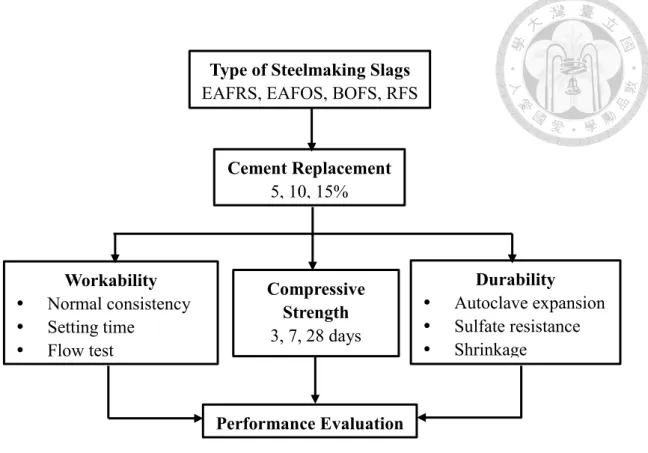
Chapter 3 Materials and Methods ………... 37
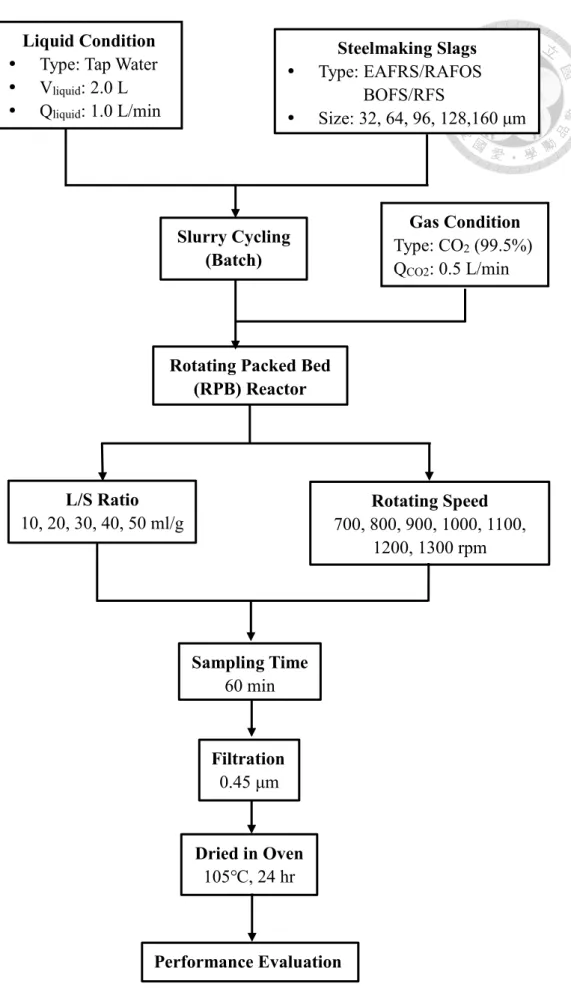
3-1 Research Flow Chart ………. 37
3-2 Materials ……….….. 39
3-2-1 Source of Feedstock ………... 39
3-2-2 Rotating Packed Bed (RPB) ……….….. 40
3-2-3 Pretreatment of Steelmaking Slags ….……… 41
3-3 Equipment ……….… 42
3-3-1 Thermal Gravimetric Analysis (TGA) ……….………...42
3-3-2 Scanning Electron Microscope (SEM) ………... 43
3-3-3 X-Ray Fluorescence (XRF) ………... 45
3-3-4 X-ray Diffractometer (XRD) ………. 46
3-4 Methods ……… 47
3-4-1 Carbonation Conversion Process ………...………..……. 47
3-4-2 Properties of Cement Replacement ………...…………. 52
3-4-3 Strength Prediction Models ……… 62
Chapter 4 Results and Discussions ………... 67
4-1 Carbonation of Steelmaking Slags through the RPB ……….……….... 67
4-1-1 Effect of Carbonation on Characteristics of Feedstock ……..……….. 67
4-1-2 Effects of Operating Parameters for Carbonation ……...……….. 73
4-2 Cement Replacement by Steelmaking Slags ……….… 80
4-2-1 Effect of Substitution on Workability of Cement ………..………80
4-2-2 Effect of Substitution on Strength of Cement ………....…………. 86
4-2-3 Effect of Substitution on Durability of Cement ………. 93
4-3 Strength Prediction Model of Clinker ………..…….. 96
Chapter 5 Conclusion and Recommendation ………...……. 105
5-1 Conclusions …..………...… 105
5-2 Recommendations ………...…… 106
References ……….……… 107
Appendix ……….……….………...……….. 115
Table of Figures
Figure 2-1 Standard Molar Gibbs Free Energy of Formation for Several Carbon-related
Substance at 298K ………...……….. 5
Figure 2-2 Relationship of CO2 Capture Capacity and Hardness for Different Types of Alkaline Wastes ………..…………. 11
Figure 2-3 Carbonation Reaction Mechanism of Alkaline Wastes. (a) Leaching of Calcium ion and CO2 Dissolution (b) CaCO3 Precipitation ………. 14
Figure 2-4 Various Types of RPB Reactors ………..……….. 16
Figure 2-5 Steelmaking Procedure ………. 18
Figure 2-6 Correlation Between Shear Strain Rate and Shear Stress ……….… 28
Figure 2-7 Schematic Diagram for Different Hydration Stage of C3S …………..….. 29
Figure 2-8 Strength Development of Different Minerals in Clinker ………... 33
Figure 3-1 Research Flow Chart in This Study ………...… 38
Figure 3-2 Material Preparation of Steelmaking Slags ………...……… 41
Figure 3-3 TGA (STA 6000) used in this study ……….. 42
Figure 3-4 Scanning Electron Microscope (SEM) ………. 44
Figure 3-5 Energy Dispersive X-ray Spectroscopy (EDX) ………. 44
Figure 3-6 X-ray Diffraction (XRD) ……….………. 47
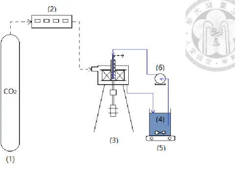
Figure 3-7 Schematic Diagram of Experimental Set-up for Carbonation in a RPB .. 48
Figure 3-8 Designs of Experimental Factors in Carbonation Process ……… 50
Figure 3-9 Flow Chart of Cement Replacement Experiment in this Research ..…… 53
Figure 3-10 Vicat Apparatus for Normal Consistency Test ………….…….……..… 54
Figure 3-11 Vicat Apparatus for Setting Test ……….. 56
Figure 3-12 Flow Table for Flow Test in this study ……… 58
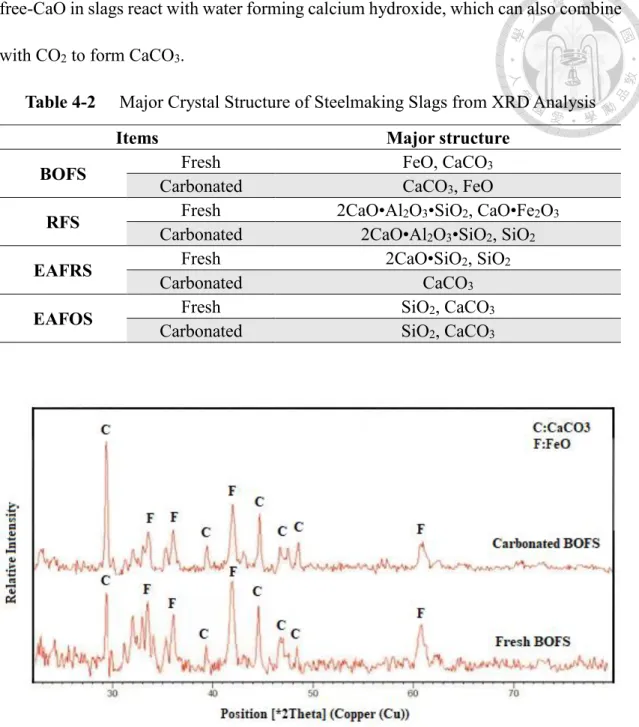
Figure 4-1 Diffraction Peak Comparison of BOFS ………. 70
Figure 4-2 Diffraction Peak Comparison of RFS ……… 71
Figure 4-3 Diffraction Peak Comparison of EAFRS ……….. 71
Figure 4-4 Diffraction Peak Comparison of EAFOS ……….…………. 72
Figure 4-5 DTG Curves of Fresh Steelmaking Slags ……….. 73
Figure 4-6 DTG Curves of Carbonated Steelmaking Slags ……….... 73
Figure 4-7 Effect Carbonation Conversion Yield under Different L/S Ratio ……..… 76
Figure 4-8 Effect of Carbonation Conversion Yield under Different Rotating Speed ……..………... 78
Figure 4-9 Effect of Particle Size on Carbonation Conversion Yield ………. 79
Figure 4-10 Standard Consistency of Paste with Different Replacing Ratio of Slags .82 Figure 4-11 Standard Fluidity of Mortars with Different Replacing Ratio of Slags ... 82
Figure 4-12 Initial Setting Time of Pastes with Different Replacing Ratio of Slags .. 85
Figure 4-13 Final Setting Time of Pastes with Different Replacing Ratio of Slags ... 85
Figure 4-14 The 3rd day Compressive Strength of Mortars with Different Replacing Ratio of Slags ……….. 90
Figure 4-15 The 7th day Compressive Strength of Mortars with Different Replacing Ratio of Slags ……….. 91
Figure 4-16 The 28th day Compressive Strength of Mortars with Different Replacing Ratio of Slags ……….………. 92 Figure 4-17 Fatal Expansion Causing by AAR in EAFOS Cement Bars …………... 92 Figure 4-18 Autoclave Expansion of Pastes with Different Replacing Ratio of Slags ..………...…… 94 Figure 4-19 Drying Shrinkage of Mortars with 10% Replacement of Slags ……….. 96 Figure 4-20 Variation in Weight Fraction of Major Compositions in Hydration Reactants ………. 98 Figure 4-21 Development of Compressive Strength of Blended Cement with Different Substitution Ratio of Steelmaking Slags ………... 103 Figure 4-22 Comparison of Predicted Compressive Strength with Measured Compressive Strength……… 104
List of Tables
Table 2-1 Carbonation Reaction of Minerals ……….... 4
Table 2-2 Summary of Accelerated Carbonation Processes Routes ………. 6
Table 2-3 Alkaline Waste in Industry ……….……….. 9
Table 2-4 Global Alkaline Wastes Production and their CO2 Emission ……….. 10
Table 2-5 Processes of Carbonation Reaction ………. 12
Table 2-6 Summary of the Characteristics and Utilizations of Portland Cements ..… 24
Table 2-7 Hydration Processes of C3S ………..…. 29
Table 2-8 Setting Processes Between Different Scenarios ……… 32
Table 2-9 Influenced Factors of Concrete Durability ……… 34
Table 3-1 Parameters of Rotating Packed Bed Used in This Study ………... 41
Table 4-1 Chemical Composition of Fresh and Carbonated Steelmaking slags from XRF Analysis ……….. 69
Table 4-2 Major Crystal Structure of Steelmaking Slags from XRD Analysis ……... 70
Table 4-3 Effect of Carbonation Conversion Efficiency Under Different Rotating Speed ……..………... 75
Table 4-4 Effect of Carbonation Conversion Yield under Different Rotating Speed .. 77
Table 4-5 Chemical Composition of Fresh EAFRS with Different Particle Size ….. 79
Table 4-6 Standard Consistency of Paste with Different Replacing Ratio of Slags ……….……… 81
Table 4-7 Setting Time of Paste with Different Replacing Ratio of Slags ………….. 84
Table 4-8 Compressive Strength of Cement Specimens at Different Curing Ages …. 89 Table 4-9 Autoclave Expansion of Pastes with Different Replacing Ratio of Slags ... 94 Table 4-10 Drying Shrinkage of Mortars with 10% Replacement of Slags ………… 95 Table 4-11 Variation in Weight Fraction of Major Compositions in Hydration Reactants
………. 97 Table 4-12 Kinetics of Compressive Strength Development of Blended Cement with Different Substitution Ratios ………...…….. 101
Comments for Oral Defense
林逸彬 教授:
Question and Suggestions Answers
為何要用RPB? RPB 較快之原因為
何?
感謝老師詢問,關於使用RPB 的原
因和其優點已於第1 章和 2-1-4 中描
述。
碳酸化轉換率該如何計算? 感謝老師提問,詳細內容已列於3-4-
1 中。
模式中的P 和 k0如何求得? 感謝老師提問,模式部分已於4-3 詳
述。
陳奕宏 教授:
Question and Suggestions Answers
建議做性質和成分做迴歸分析。 感謝老師建議,未來會加入ANOVA
分析化學成分對水泥性質的影響。
未來方向除LCA,應更在意經濟效益
分析。
感謝老師建議,會列入未來考量並在 5-2 加以修正。
可結合廢氣之實際二氧化碳濃度評 估。
感謝老師建議,實驗室正在進行模擬
實場煙道氣15%二氧化碳去除實驗。
顧洋 教授:
Question and Suggestions Answers
參考資料應該補齊,格式統一。 感謝老師建議,格式方面已經予以修
正。
XRF 測定之缺點(定性,非定量)是否 造成測定不準。
感謝老師提問,根據參考資料XRF
測得結果與ICP 相近,後續會再進行
相關實驗核實。
文中碳酸化轉化率conversion yield
與conversion 算法有何不同?文中應
用該採用何者?
感謝老師提問,conversion yield 為氧 化鈣轉變為碳酸鈣的產出率,而 conversion 則單純為二氧化碳轉變為 碳酸鈣的比率,本研究使用的試驗方 法皆屬於前者。
強度預測模式僅是回歸公式,有無物
理意義?為何不使用kt,而是 k
ln(t)?
感謝老師提問,目前 4-3 的模式僅為 回歸公式,後續會結合 ANOVA 分析進 行化學成分對強度的探討。
Chapter 1 Introduction
Steelmaking industry plays an important role of industry development. According to the report provided by World Steel Association, the amount of crude steel production and steel consumption per capita in Taiwan ranked 12 and 2 respectively in the world.
However, steelmaking is a high pollutant industry, which not only emits a great amount of carbon dioxide but also produce a lot of alkaline waste. As the situation of global warming grows intensively, fighting against greenhouse gases (GHGs) should not be delayed. Carbon dioxide is the most important anthropogenic GHGs, which is responsible for about two third of the enhanced greenhouse effect. According to the information provided by intergovernmental panel in climate change (IPCC), the global CO2 emission reached to 49 Gt in 2010. In the meanwhile, international energy agency (IEA) also proposed that the techniques of carbon capture, utilization and storage (CCUS) can lead to the reduction of CO2 up to 15%. Therefore, people have gradually laid more emphases on the techniques of CCUS.
CCUS can be divided into carbon capture and storage (CCS) and utilization (CCU).
While people conduct CCS, many restrictions must be taken into consideration. For example, people need to choose the suitable geological storage, such as anticline. The storage might also cause earthquakes. What’s more, the process of the storage can’t provide any economic benefit. On the other hand, CCU can be used as chemical feedstock, fuel, enhanced oil recovery, mineral carbonation, which can provide extra
mineral carbonation is equipped with thermodynamically stability. Besides, carbonation is an exothermic reaction, which doesn’t need extra energy consumption.
It also lowers environmental impacts. Thus, mineral carbonation is regarded as the most acceptable technique in CCUS.
In consideration of green chemistry and economical effect, alkaline waste from the steel industry mentioned above can be used as carbon-catching materials because it contains a large amount of calcium oxide. In the meanwhile, the process of carbonation can also neutralize the alkalinity of the waste. However, during carbonation, the low diffusion rate of calcium ion may be the rate determined step in the reaction. In order to elevate the efficiency and rate of carbonation, the effect of mass transfer has to be improved. In this study, rotating packed bed is employed because it can break liquid drops into even smaller particles to enhance mass transfer rate. Carbonated alkaline waste can be used as a kind of pozzolanic material, which can be added into cement to intensify its properties. In this way, the outcome can reach to the aim of cleaner production and circular economy. In conclusion, the objectives in this study includes:
1. To evaluate the performance for carbonation conversion by different steelmaking slags.
2. To investigate the properties of cement with partial replacement by different steelmaking slags.
3. To establish the strength prediction model of mortar replaced by different steelmaking slags.
Chapter 2 Literature Review
2-1 Carbonation Process
2-1-1 Accelerated Carbonation
To mitigate the global warming, many kinds of technology have been developed for each phase of carbon capture utilization and storage. CO2 may be captured from post-combustion, pre-combustion or oxy-fuel combustion technology. After capturing, the mineralization method is regarded as a promising and feasible alternative to CO2
sequestration. Mineral carbonation is a chemical process in which CO2 reacts with a metal oxide such as magnesium or calcium to form carbonates. Magnesium and calcium are normally found in nature in the form of silicate minerals such as serpentine, olivine,
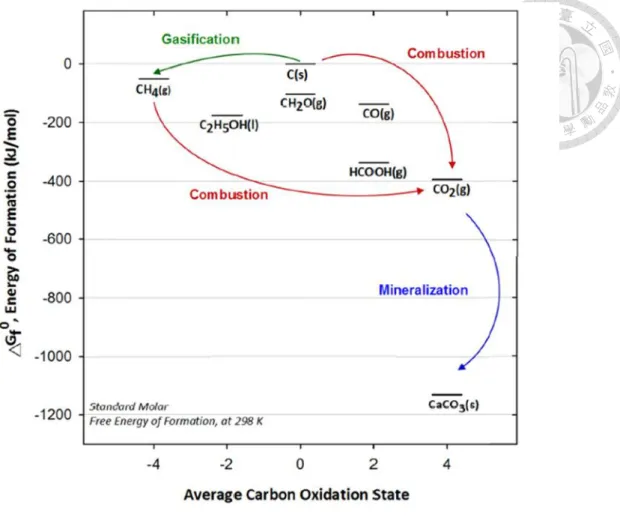
wollastonite and etc., which are largely deposited in Finland, Australia, Portugal and the USA. All of these mineral carbonation reactions, which is called weathering, are shown in table 2-1 (Zha et al.,2015). They can occur spontaneously in nature due to the products of these reactions which have lower Gibbs free energy than reactant as in figure 2-1. However, the reaction rate of nature carbonation is too slow due to the relative low CO2 concentration in the atmosphere, which is about 400 ppm (Bertos et al., 2004). Thus, the accelerated carbonation was proposed by Seifritz in 1990 by using minerals as feedstock to react with a high purity of CO2 and was proven thermodynamically practical to enhance natural weathering process (Lackner et al., 2005). Costa et al. (2007) also indicated that the accelerated carbonation process has
Table 2-1 Carbonation Reaction of Minerals (Zha et al., 2015)
Minerals Reaction equation
ΔH (kJ/mol) Anorthite
𝐶𝑎𝐴𝑙2𝑆𝑖2𝑂8+ 𝐶𝑂2 →
𝐶𝑎𝐶𝑂3+ 𝐴𝑙2𝑂3+ 2𝑆𝑖𝑂2 -81 Calcium
Hydroxide
𝐶𝑎(𝑂𝐻)2+ 𝐶𝑂2 → 𝐶𝑎𝐶𝑂3+ 𝐻2𝑂 -68 Chrysotile
(Serpentine)
𝑀𝑔3𝑆𝑖2𝑂5(𝑂𝐻)4+ 3𝐶𝑂2 →
3𝑀𝑔𝐶𝑂3+ 2𝑆𝑖𝑂2 + 2𝐻2𝑂 -35 Diopside
𝐶𝑎𝑀𝑔𝑆𝑖2𝑂6+ 2𝐶𝑂2 →
𝐶𝑎𝐶𝑂3+ 𝑀𝑔𝐶𝑂3+ 2𝑆𝑖𝑂2 -71 Enstatite 𝑀𝑔2𝑆𝑖2𝑂6+ 2𝐶𝑂2→ 2𝑀𝑔𝐶𝑂3+ 2𝑆𝑖𝑂2 -81 Forsterite
(Mg-Olivine)
𝑀𝑔𝑆𝑖𝑂4+ 2𝐶𝑂2 → 2𝑀𝑔𝐶𝑂3+ 𝑆𝑖𝑂2 -88 Grossular
Garnet
𝐶𝑎3𝐴𝑙2(𝑆𝑖𝑂4)3+ 3𝐶𝑂2 → 3𝐶𝑎𝐶𝑂3+ 𝐴𝑙2𝑂3+ 3𝑆𝑖𝑂2
-67
Lime 𝐶𝑎𝑂 + 𝐶𝑂2 → 𝐶𝑎𝐶𝑂3 -167
Magnesium Hydroxide
𝑀𝑔(𝑂𝐻)2+ 𝐶𝑂2 → 𝑀𝑔𝐶𝑂3+ 𝐻2𝑂 -37
Periclase 𝑀𝑔𝑂 + 𝐶𝑂2 → 𝑀𝑔𝐶𝑂3 -115
Pyrope Garnet
𝑀𝑔3𝐴𝑙2(𝑆𝑖𝑂4)3+ 3𝐶𝑂2 →
3𝑀𝑔𝐶𝑂3+ 𝐴𝑙2𝑂3+ 3𝑆𝑖𝑂2 -92 Talc
𝑀𝑔3𝑆𝑖4𝑂10(𝑂𝐻)4+ 3𝐶𝑂2 →
3𝑀𝑔𝐶𝑂3+ 4𝑆𝑖𝑂2+ 𝐻2𝑂 -44 Tremolite
𝐶𝑎2𝑀𝑔5𝑆𝑖8𝑂22(𝑂𝐻)2+ 7𝐶𝑂2 →
2𝐶𝑎𝐶𝑂3+ 5𝑀𝑔𝐶𝑂3+ 8𝑆𝑖𝑂2+ 𝐻2𝑂 -37 Wollastonite 𝐶𝑎𝑆𝑖𝑂3+ 𝐶𝑂2 → 𝐶𝑎𝐶𝑂3+ 𝑆𝑖𝑂2 -87
Figure 2-1 Standard Molar Gibbs Free Energy of Formation for Several Carbon- related Substance at 298K (Pan et al. 2015)
Accelerated carbonation processes can be divided into two categories: the direct carbonation process and the indirect carbonation process, which are shown in Table 2-2. The direct carbonation process is the carbonation taking place in a single step, which can be accomplished via gas-solid reactions or mineralization in aqueous solutions. The indirect carbonation process takes place in a multi-step process. It includes hydrochloric (HCl) acid extraction, the molten salt process, other acid extraction, bioleaching, ammonia extraction and caustic extraction followed by
Table 2-2 Summary of Accelerated Carbonation Processes Routes. (Bobicki et al., 2012) Mineral carbon
sequestration methods Characteristics
Direct carbonation
Gas-solid
CO2 reacted with mineral in a gas-solid reaction
Simplest method of mineral carbonation
Not feasible for silicate minerals Aqueous
CO2 reacted with mineral in aqueous suspension
Pre-treatment required
Most promising technique
Indirect carbonation
HCl Extraction
Metal ion extracted from mineral using HCl
Metal ion precipitated as hydroxide for carbonation
HCl recovered
Very energy intensive
Molten Salt
Molten magnesium chloride salt used to extract metal ion from silicate minerals
Molten salt highly corrosive
Make-up chemical cost is prohibitive
Acid Extraction
Acids used to extract metal ion from minerals
Extracted metal carbonated
Various acids used
High carbonate conversions achieved
Multiple process steps allow contaminants to be separated, resulting in a pure carbonation product
Chemically intensive
Energy intensive if acid recovered
Bioleaching
Chemolithotrophic bacteria combined with acid generating substances and silicate minerals to extract metal ions for aqueous carbonation
Passive and inexpensive
Ammonia Extraction
Ammonia salts used to extract metal ion from silicate rock for carbonation
Selective leaching of alkaline earth metals
Reagent recovery possible
Reasonable carbonate conversions achieved Caustic
Extraction
Caustic solid used to extract metal ion from silicate rock for carbonation
Not a promising technique
2-1-1-1 Direct Carbonation
The processes of carbonation of the solid minerals or alkaline wastes, which take place in a single route step, are called the direct carbonation processes. In these processes, reaction conditions such as temperatures and pressure have significant influence on the reaction rate. The processes can be divided into two types for discussion, which are carbonation in gaseous (gas-solid) and aqueous phase.
The gas-solid process is the simplest method of mineral carbonation and it can usually produce high temperature steam and electricity during the converting process.
However, the performance of reaction, such as reaction rate and carbonation conversion yield of minerals, is still too poor to be utilized due to the thermodynamic limitations (Sipilä et al. 2008).
In the aqueous process of direct carbonation, CO2 reacts with water to form carbonic acid and bicarbonate which can react with metal ion from mineral to form carbonate precipitation (Bobicki et al. 2012). It seems to be the most promising CO2
mineralization alternative to date due to the reaction rate and the carbonation degree are more acceptable. However, the cost of pre-treatment steps during the aqueous accelerating carbonation process is higher than that in the gas-solid carbonation process (Sipilä et al. 2008).
2-1-1-2 Indirect Carbonation
Indirect mineral carbonation refers to the mineral carbonation processes, which take place in more than one stage. Typically, indirect carbonation involves the extraction of reactive components (Mg2+, Ca2+) from the minerals, using acids or other solvents, followed by the reaction of the extracted components with CO2 in either the gaseous or aqueous phase. For example, the processes of using acetic acid to extract calcium ion from wollastonite. After extraction, the residue minerals are removed and carbon dioxide dissolves in the calcium-containing solution to form calcium carbonate precipitation. The reaction is shown in Eq. 2-1 and 2-2.
𝐶𝑎𝑆𝑖𝑂3+ 2𝐶𝐻3𝐶𝑂𝑂𝐻 → 𝐶𝑎2++ 2𝐶𝐻3𝐶𝑂𝑂𝐻−+ 𝐻2𝑂 + 𝑆𝑖𝑂2 (2-1)
𝐶𝑎2++ 2𝐶𝐻3𝐶𝑂𝑂𝐻−+ 𝐻2𝑂 + 𝐶𝑂2 → 2𝐶𝐻3𝐶𝑂𝑂𝐻 + 𝐶𝑎𝐶𝑂3 ↓ (2-2)
The main advantage of indirect carbonation processes compared to the direct one is pure calcium carbonate, which can be produced due to the removal of other impurities during the leaching process. Pure calcium carbonate can be marketed at a higher price, which contributes to more capital investment for the carbonation process (Eloneva et al. 2008).
2-1-2 Alkaline Wastes Utilization for Accelerated Carbonation
Both natural minerals and alkaline wastes can be used in carbonation process, however, alkaline wastes from the industry have not only higher carbon capture capacity but also lower energy consumption during mining. As presented, an enormous amount of industry alkaline waste is produced by the steelmaking industry, the thermal power plants, the cement industry, the paper-manufacturing industry and the petrochemical industry. Alkaline wastes often seen above are summarized in Table 2-3:
Table 2-3 Alkaline Waste in Industry (Pan et al. 2012)
Alkaline Solid Waste Group Example
Slag Steelmaking slags (BOFS, EAFS, BFS)
Coal slag Air pollution control residue
Municipal solid waste incinerator (MSWI) APC residue
Cyclone dust Fly ash
MSWI fly ash
Coal fly ash
Oil shale ash Bottom ash MSWI bottom ash
Cement wastes
Cement kiln dust
Cement bypass dust
Construction and demolition waste
Cement / Concrete waste
Blended hydraulic slag cement Mining waste
Asbestos tailings
Nickel tailings
Bauxite tailing Sludge (incinerator) ash
Sewage sludge incinerator ash
Steel wastewater sludge
Paper sludge incinerator ash
Paper pulping and mill waste
Paper mill waste (calcium mud)
Green sludge dreg
Lime mud
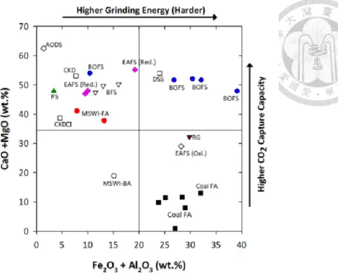
The alkaline wastes are abundant, cheap, and usually cogenerated with CO2 (Table 2-4) in many industries, so they are suitable in carbonation. Figure 2-2 summarized the relationship between CO2 capture capacity in terms of CaO and MgO contents and hardness in terms of Fe2O3 and Al2O3 contents for different types of solid wastes. In general, the contents of CaO and MgO in the steelmaking slags are relatively higher than those in the fly ash or bottom ash. Thus, steelmaking slags such as blast-furnace slags (BFS), basic-oxygen-furnace slag (BOFS), and electric-arc-furnace slags (EAFS) have the advantage of carbon capture.
Table 2-4 Global Alkaline Wastes Production and their CO2 Emission (Azdarpour et al., 2015)
Alkaline Wastes
Global Production (Mt/yr)
CO2 Emission (Mt/yr)
Steelmaking Slags 315-420 171
Waste Cement 1100 62
Coal Fly Ash 600 12000
Red Gypsum 1.25 3.6
Figure 2-2 Relationship of CO2 Capture Capacity and Hardness for Different Types of Alkaline Wastes (Pan et al. 2015)
2-1-3 Mechanism of Carbonation Process
Carbonation reaction is an exothermic reaction, which can be divided into three steps. Firstly, calcium ion is leached from minerals or the alkaline wastes and dissolved in the solution. Secondly, CO2 is dissolved in the solution simultaneously to form carbonic acid (H2CO3), which will be ionized into bicarbonate and carbonate in alkaline condition. Finally, calcium ion reacts with bicarbonate and carbonate to form precipitation of calcium carbonate. The processes of mineral carbonation is shown in Table 2-5. (Huijgen et al., 2005; Huntzinger et al., 2009; Haug et al., 2011)
Table 2-5 Processes of Carbonation Reaction
Step Reaction
Leaching of Calcium ion
CaO + 𝐻2𝑂 → 𝐶𝑎2++ 2𝑂𝐻− (alkaline wastes) 𝐶𝑎2𝑆𝑖𝑂4+ 4𝐻2𝑂 → 2𝐶𝑎2++ 𝐻4𝑆𝑖𝑂4+ 4𝑂𝐻− (minerals) CO2 Dissolution
and Ionization
𝐶𝑂2+ 𝐻2𝑂 → 𝐻2𝐶𝑂3
𝐻2𝐶𝑂3 ↔ 𝐻++ 𝐻𝐶𝑂3− ↔ 2𝐻++ 𝐶𝑂32−
CaCO3
Precipitation
𝐶𝑎2++ 𝐻2𝐶𝑂3 → 𝐶𝑎𝐶𝑂3 ↓ +2𝐻+ 𝐶𝑎2++ 𝐻𝐶𝑂3− → 𝐶𝑎𝐶𝑂3 ↓ +𝐻+
𝐶𝑎2++ 𝐶𝑂32− → 𝐶𝑎𝐶𝑂3 ↓
Additionally, the reaction rate is also influenced by factors as follow:
a) Transportation-controlled mechanisms of Ca2+ and CO32- diffusion.
b) Boundary layer effect of diffusion across silica-rich layer and CaCO3 coating layer.
c) Precipitate coating.
d) Pore blockage.
e) Dissolution of Ca2+ from minerals and alkaline waste.
Where a) and b) are usually affected by reactor categories and reaction condition, c) and d) are mainly influent by the material characters, and e) is affected by the liquid agent categories and the material characters.
(a)
(b)
Figure 2-3 Carbonation Reaction Mechanism of Alkaline Wastes. (a) Leaching of
2-1-4 Rotating Packed Bed (RPB)
2-1-4-1 Features and Characteristics
In 1979, the rotating packed bed (RPB) was designed by Ramshaw and Mallinson for intensifying the mass transfer between the gas and the liquid in the distillation and absorption process. In the PRB reactor, the thinner liquid film and the smaller liquid drops can be provided by a high centrifugal force, which contributes to 10 to 100 times of mass transfer coefficient (Lin et al., 2011). Compared with the traditional packed bed (PB), the advantages of RPB reactor are concluded as follows:
a. RPB has better performance in micro-mixing and mass transfer.
b. RPB has higher flooding capacity that can be operated at the higher gas and liquid flow rates.
c. Smaller size of reactor is needed due to its high reaction rate. Thus, the capital and operation costs can be reduced. (Ramshaw, 1983)
d. RPB has higher self-cleaning ability to prevent blocking in packing material.
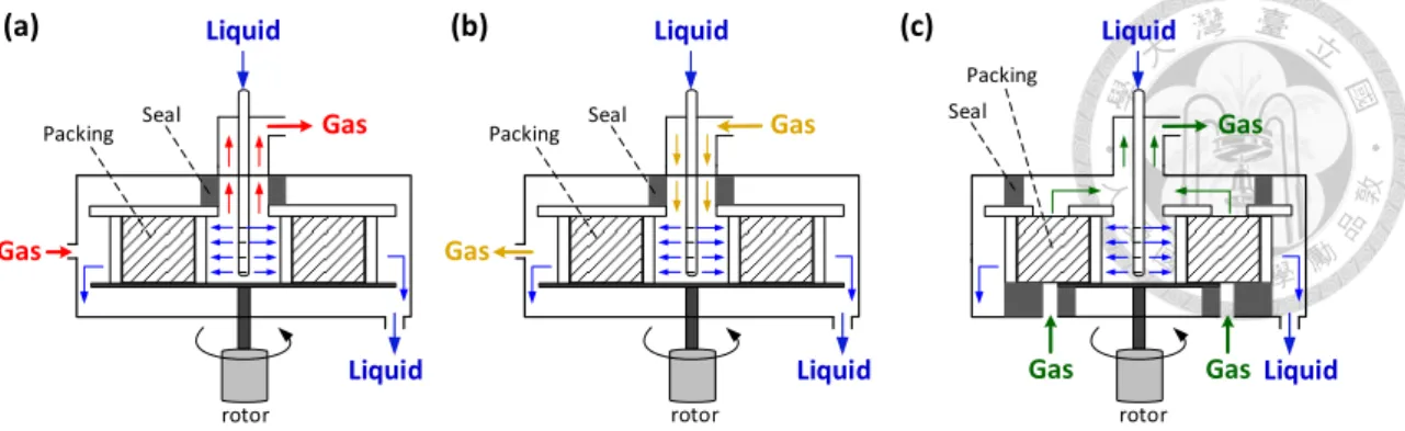
The RPB reactors can be divided into 3 categories according to flowing direction of gas and liquid as in figure 2-4. In the countercurrent type, the liquid is sprayed from the center of the RPB and move outward through the packing materials. In the meanwhile, the gas flows inward from the outer edge of RPB and react with the liquid drops. In the co-current type, the liquid and the gas move outward from the center of the reactor spontaneously. In the cross-flow type, the gas moves from the bottom to the top of the reactor and intersect with the liquid flow orthogonally.
Figure 2-4 Various Types of RPB Reactors: (a) Countercurrent flow, (b) Co-current flow, (c) Cross-flow.
2-1-4-2 Mass transfer Coefficient
Mass transfer coefficient of liquid-gas reaction is based on two-film theory. In this theory, the area near the liquid-gas interface can be divided into parts as bulk liquid, liquid film, gas film, and bulk gas. Molecules in the bulk phase are assumed to move by convection and mass transfer in the film is assumed to be diffusion motivated by concentration gradient. The overall mass transfer coefficient of gas in this theory can be expressed as:
1 𝐾𝑂𝐺 = 1
𝐾𝐺+ 𝐻
𝐾𝐿 (2-3) where KOG is the overall mass transfer coefficient, H is the Henry’s law constant, KG is the mass-transfer coefficient in the gas film, KL is the mass-transfer coefficient in the liquid film. Owing to the solubility of CO2, mass transfer in this reaction is controlled by the gas-film. Thus, KOG can be regarded as KG, and KG may be estimated by eq. 2-4 (Liu et al., 2013):
𝐾𝐺
𝒟𝐺𝑎𝑡 = 2𝑅𝑒𝐺0.7𝑆𝑐𝐺1⁄3(𝑎𝑡𝐷𝑝)−2 (2-4)
(a) Liquid
Liquid Gas
Gas
(b) Liquid
Liquid Gas
Gas
(c) Liquid
Liquid Gas
Gas Gas
Packing Seal Seal
Packing Seal
Packing
rotor rotor rotor
where 𝒟G presents the diffusion coefficient of the gas-film; Dp is the droplet diameter;
at is the total surface area of packing materials. Then the gas-liquid surface area can be
calculated by eq. 2-5 (Onda et al., 1968):
𝑎
𝑎𝑡 = 1 − exp[−1.45(𝜎𝑐
𝜎)0.75𝑅𝑒𝐿0.1𝑊𝑒𝐿0.2𝐹𝑟𝐿−0.05] (2-5) Dimensionless numbers in (2-4) and (2-5) is listed as follow:
Reynolds number: 𝑅𝑒𝐿= 𝐿
𝑎𝜇𝐿
Schmidt number: 𝑆𝑐𝐿 = 𝜌𝐿
𝜇𝐿𝑔
Grashof number: 𝐺𝑟𝐿 = 𝑔𝑑𝑝3(𝜌𝐿
𝜇𝐿)2 Froude number: 𝐹𝑟𝐿 = 𝜇𝑔
2 𝜀2𝑔𝛿
Weber number: 𝑊𝑒𝐿 =𝜇𝑔2𝛿𝜌𝐿
𝜀2𝜎𝐿
where a is the wet surface area of packing material; μL is the viscosity of the liquid agent. Then the RPB sizes and operation parameters can be determined by KGa in eq.
2-6:
𝐾𝐺𝑎 = 𝑄𝐺
𝜋𝑍(𝑟𝑜2−𝑟𝑖2)𝑁𝑇𝑈 = 𝑄𝐺
𝜋𝑍(𝑟𝑜2−𝑟𝑖2)ln(𝑌𝑖
𝑌𝑜) (2-6) and HTU in rotating packed bed can be obtained as eq. 2-7 (Cheng and Tan, 2011):
𝐻𝑇𝑈 = 𝑟𝑜−𝑟𝑖
𝑙𝑛(𝑌𝑖
𝑌𝑜) (2-7) where ro and ri is the outer and inner diameter of the packing material; Z is the height of the packing material, and Yi and Yo is the concentration of gas at inflow and outflow.
According to the experimental results of Pan et al., the performance during the High- Gravity Carbonation Process, such as carbonation conversion yield and the reaction rate is proven to be better than other traditional methods.
2-2 Alkaline Waste from Steelmaking
Steelmaking industry plays an important role of economic development. However, different kinds of wastes are produced simultaneously which are difficult to deal with.
Figure 2-5 elaborates the procedure of steelmaking, including consistent operation of steelmaking and electric arc furnace steelmaking. The detailed principles and procedures will be shown in this section.
Figure 2-5 Steelmaking Procedure
2-2-1 Blast Furnace
A blast furnace (BF) is a type of metallurgical furnace used for smelting to produce industrial metals, generally pig iron. In a blast furnace, fuel (coke), ores, and flux (limestone) are continuously supplied through the top of the furnace and stack alternately. In the meanwhile, air with oxygen enrichment reacts with coke to produce carbon monoxide and heat as in eq. 2-8.
𝐶 + 𝑂2 → 𝐶𝑂 + ℎ𝑒𝑎𝑡 (2-8) After that, the hot blast air is blown into the lower section of the furnace and reacts with the material falls downward as in eq. 2-9 to 2-11.
𝐹𝑒2𝑂3+ 3𝐶𝑂 → 2𝐹𝑒3𝑂4+ 𝐶𝑂2 (2-9) 𝐹𝑒3𝑂4+ 𝐶𝑂 → 3𝐹𝑒𝑂 + 𝐶𝑂2 (2-10) 𝐹𝑒𝑂 + 𝐶𝑂 → 𝐹𝑒 + 𝐶𝑂2 (2-11) As the material travels downward, the counter-current gases both preheat the feed charge and decompose the limestone to calcium oxide and carbon dioxide. The calcium oxide can react with various acidic impurities in the iron (notably silica) to form a calcium silicate slag.
𝐶𝑎𝐶𝑂3→ 𝐶𝑎𝑂 + 𝐶𝑂∆ 2 (2-12) 𝑆𝑖𝑂2+ 𝐶𝑎𝑂 → 𝐶𝑎𝑆𝑖𝑂3 (2-13) After the reaction, the molten iron and blast furnace slag are tapped from the bottom separately. Molten iron produced by the blast furnace is called the pig iron, which contains carbon more than 2 percent. Unfortunately, carbon in the pig iron makes
it hard and brittle, which is hard to forge and process. Thus, another process is needed to purify the impurities, such as carbon, sulfur, and phosphorus in the pig iron.
Slag from BF can be divided into two categories according to the differences of the cooling procedure. The slag cooling naturally after being taken out from the BF is named as the air-cooling blast furnace, and it can be used as concrete aggregate after being crushed and graded due to its hardness and strength. The properties of the slags vary with their composition and the rate of cooling. Acid slag generally produces a denser aggregate, and basic slag tends to produce a vesicular or honeycombed structure with a lower apparent specific gravity. On the whole, the bulk density of air-cooling slag typically ranges from 1120 to 1360 kg/m3, which is between the normal-weight natural aggregate and structural lightweight aggregate.
Another category of BF slag is called the water-quenching blast furnace slag, which is rapidly cooled by the high-pressured water after being obtained from the BF.
Glassy surface and amorphous structure are developed in this type of slag due to the rapid cooling procedure. Since the defects and element replacement in the crystal may cause activity, grounded water-quenching blast furnace slag is weakly cementitious and pozzolanic, which can be used as a kind of mineral admixture in concrete to improve the strength development.
2-2-2 Basic Oxygen Furnace
Basic oxygen furnace is the place where turns the molten pig iron into steel by an oxygen converter process. As mentioned above, the pig iron produced from the blast furnace is rich in carbon due to cokes added as reducing agents and fuels. Among the constitution of pig iron, carbon mainly exists as iron carbide (Fe3C) which makes the pig iron brittle and hard. In order to solve this problem, process is used to improve the tenacity of iron and makes it easier to forge. In the oxygen converter process, oxygen is blown into the molten pig iron to reduce the carbon content and changes it into low- carbon steel.
In addition, chemical base materials such as burnt lime and dolomite are added as fluxes to lower the melting point and absorb the impurities in the molten iron to form slag. The BOF slag is rich in calcium silicates, which are similar to the clinker of Portland Cement. The slag after rapid cooling may generate cementing ability that can be regarded as a kind of pozzolanic material in the concrete. In addition, BOF slag can be used as aggregate of Portland concrete or asphalt concrete due to its abrasion rate and soundness. However, free-CaO and free-MgO in the slag may cause expand after reacting with water that modification or stabilization should be adopted before using.
The content of sulfur and phosphorous in the BOF molten steel may be to high because they are hard to be removed in a oxygen-rich condition. Therefore, another refining process is needed to improve its purity. During the process, molten steel is first placed in a ladle furnace. Desulfurizer such as calcium alloy (CaSi) or CaO-Al2O3-CF2
are added after that to combine with sulfur. After cooling, CaO-FeO is added to bind with phosphorous.
2-2-3 Electric Arc Furnace
Instead of using ores as raw materials in consistent operation of steelmaking, the electric arc furnace (EAF) process smelts the ferrous scrap by means of an electric arc to produce steel. Thus, the EAF process has a lower fuel consumption and CO2 emission.
Moreover, comparing with the BF cannot vary their production by much, the EAF is more flexible in steelmaking due to it can be rapidly started and stopped to vary production according to demand. However, impurities in ferrous scrap such as sulfur, phosphorous or even organic materials may affect the quality of steel, so other processed is needed to purify them.
The EAF process can be divided into three periods: melting, oxidation and reduction. At the beginning, ferrous scrap and flux such as lime or dolomite are added into the EAF. After the roof and the graphite electrodes moving down, electrical energy is supplied to melting operations. During the melting period, lime and ores are added appropriately to remove prosperous and fluorite is added to enhance the fluidity.
Once all of the scrap is melted, oxidant is added for further dephosphorization and decarburization. In the early stage of the oxidation period, iron ore and lime would react with phosphate as eq. 2-14 and 2-15:
5𝐹𝑒𝑂 + 2𝐹𝑒3𝑃 → 𝑃2𝑂5+ 11𝐹𝑒 (2-14) 𝑃2𝑂5+ 3𝐶𝑎𝑂 → 3CaO ∙ 𝑃2𝑂5 (2-15)
Later, the EAF is heated to 1550℃ and the oxygen and the iron ore are added into the furnace to oxidize the residual carbon. The reaction is shown in eq. 2-16 and 2-17:
𝐶 + 𝑂 → 𝐶𝑂 (2-16) 𝐹𝑒𝑂 + 𝐶 → 𝐹𝑒 + 𝐶𝑂 (2-17) The impurities after reaction may float on the top of the melting phase and combine to form the oxidation slag. Due to its hardness, high density and abrasion resistance, the slag through the removing, cooling and sorting processes can be used as asphalt concrete aggregate.
After all of the oxidation slags are removed, the melting steel is transferred to a ladle furnace for reduction and refining. The most important task in this period is deoxidation and desulfurization by adding manganese, lime, fluorite, silicates and toner.
As the reduction reaction proceeds, a thin layer of reduction slag is formed gradually.
Different with the oxidation slag, the reduction slag has a higher calcium and lower iron contents. Owing to the free-CaO and free-MgO may cause expansion during absorption of moisture, the reduction slag has to be stabilized before utilization.
2-3 Cement Chemistry
Hydraulic cement is a gel-material for binding aggregates. After water added, the cement will harden gradually hydration reaction. Compare to other kinds of cement, Portland Cement (PC) has higher durability and lower manufacturing cost. The most popular category of Portland cement is type I which is widely used in driveway, railway, military constructions. There are four other derivative types that applicable to different scenarios. Table 2-6 lists the properties of utilizations of typical Portland cements.
Table 2-6 Summary of the Characteristics and Utilizations of Portland Cements
Class Property Implementation
Type I Non-specific requirement Regular construction Type II Moderate sulfate resistance and
hydration heat Drainage, Foundations Type III High early strength Cold-weather constructions Type IV Low hydration heat Massive construction
Type V High sulfate resistance Foundations in high-sulfate soils
2-3-1 Composition of Portland Cement Clinker
The principal feedstock of Portland cement are limestone and clay, which provide calcium and silica-alumina respectively. During the process of heating raw materials to 1450 ℃, clinker materials will be crystallized according to the following sequences:
1. Moisture in the raw materials will be removed at 100℃
2. Crystallization water will be removed and the raw materials are decomposed to SiO2 and Al2O3 at 400 to 600℃.
3. Calcium carbonate in limestone will be decomposed into calcium oxide and carbon dioxide at about 800℃. Later, CaO will combine SiO2 to form dicalcium silicate (C2S, 2CaO·SiO2).
4. CaO starts to combine Al2O3 and Fe2O3 to form tricalcium aluminate (C3A, 3CaO∙Al2O3) and tetracalcium aluminoferrite (C4AF, CaO∙Al2O3∙Fe2O3) at 900 to 1100℃.
5. Compounds start to melt into the liquid phase and the C2S can combine the melting lime to create tricalcium silicate (C3S, 3CaO·SiO2) at 1200 to 1450℃
6. The products from the rotary kiln are rapidly cooled down to ensure the stability of β-C2S, and the gypsum is added to control the setting time of the clinker. Finally, the clinker is ground into powder to store.
In these components of the clinker, C3S make up most of the total mass, even up to 55% of all. It plays the most important role not only in strength development due to its high hydration rate but also in producing high strength hydration products. Thus,
rate and hydration heat. The structure of C3S is the crystallization of isolated silicon oxygen tetrahedron and calcium ions. C3S crystal structures at different temperatures are listed as below:
𝑇1620↔ 𝑇℃ 2920↔ 𝑇℃ 3980↔ 𝑀℃ 1990↔ 𝑀℃ 2 1060↔ 𝑀℃ 31070↔ 𝑅 ℃
Where T corresponds to triclinic, M to monoclinic, R to rhombohedral. According to the unbalance of coordination, C3S is relatively active, which can react with water molecules faster than C2S.
C2S in cement is divided into three categories according to temperatures and the cooling rates. α-C2S is formed in high temperature and turns to β-C2S and γ-C2S during cooling.
γ500↔ 𝛽℃ 650↔ 𝛼′℃ 𝐿1160↔ 𝛼′℃ 𝐻1425↔ 𝛼 ℃
Among them, β-C2S is the major strength contributor to the final strength for cement and concrete due to its unbalance of coordination. However, C2S will turn into γ phase, which is formed during natural cooling and is too stable to react with water. In addition, 10% of volume expansion will occur during the phase change from β to γ.
Thus, rapid cooling of the clinker to keep C2S in the β phase is important.
C3A, usually existing in vitreous texture, also plays an important role in the early strength development due to its hydration reaction, which can arise immediately.
However, rapid hydration may not only cause flash setting to reduce the workability but also produce a great amount of heat liberation. What’s more, hydration product of C3A can’t provide enough strength, which may cause defect in the cement and concrete structure. To prevent the disadvantage of C3A reaction, gypsum is added to react with
C3A and form ettringite (AFt, C3A∙3CaSO4∙32H2O) and monosulfoaluminate (AFm, C3A∙CaSO4∙12H2O).
The formation of C4AF is similar to C3A, which can be regarded as a solid solution of C2A-C2F. Because the hydration reaction of C4AF can be decelerated significantly, its heat liberation is lower than C3A, which can prevent exothermic expansion of mass concrete. Additionally, hydration products from C4AF and gypsum have better sulfate resistant compared with those from C3A. Although C4AF isn’t considered to be a strength contributor to cement and concrete, Bytt et al. pointed out that ions such as V5+, Ti4+, Mn4+ exchanged Fe3+ in the crystal may improve the hydraulic activity to enhance the strength development of C4AF.
Except for major compositions mentioned above, there are still other minor compositions in the clinker, which may influence the durability of cement. During the calcination process of the clinker, partial of lime doesn’t combine other raw materials.
Besides, a small amount of C3S may decompose into C2S and CaO during the cooling process. These two types of CaO which exist in the clinker are also called free-CaO, which will cause fatal expansion after hydration. Similarly, free-MgO in the clinker can also react with water, which also produces the same effect to damage the microstructure of the cement.
Another important minor composition in the clinker is alkali, which includes sodium and potassium. During the hydration, Alkali ions can react with silicates and aluminates in the aggregates to form Na2SiO3 gel, which may expand after water
2-3-2 Properties of Fresh Concrete
The properties of fresh concrete can be discussed in workability and the setting time. The workability influences the adhesion between concrete and templates to avoid structural defects caused by cavities. However, the workability tests of cement and concrete are usually empirical and it is hard to compare results from one test to another.
Fortunately, rheology provides a fundamental measurement for flowing. By comparing the linear regression results between different samples and Portland Cement, chemical admixtures are considered to be added for fluidity adjustment.
Figure 2-6 Correlation Between Shear Strain Rate and Shear Stress
Apart from workability, setting time also plays an important role in the properties of the fresh concrete. An appropriate setting time not only ensures that concrete can maintain in plasticity during transporting and pouring but also demonstrates that the strength can be built in a period of time. Calcium silicates, which make up more than
80% of mass, play an important role in cement hardening. The hydration reaction of C3S and C2S is shown in eq. 2-18 and 2-19:
2𝐶3𝑆 + 6𝐻 → 𝐶3𝑆2𝐻3+ 3𝐶𝐻 (2-18) 2𝐶2𝑆 + 4𝐻 → 𝐶3𝑆2𝐻3+ 𝐶𝐻 (2-19) However, C2S compared with C3S is less active to hydrate. Therefore, its contribution to setting can be neglected. The hydration model of C3S proposed by Young and Skany is divided into five processes as table 2-7:
Table 2-7 Hydration Processes of C3S
Figure 2-7 Schematic Diagram for Different Hydration Stage of C3S Stage Rate Determining Step Rate Properties Related to Concrete
I Dissociation Fast
II Nucleation Slow Initial Setting Time
III Hydration reaction Fast Final Setting Time IV Hydration and Diffusion Moderate
V Diffusion Slow Compressive Strength
⚫ Stage I: Once the water is added to react with calcium silicates, Ca2+ and OH- start to dissociate accompanying heat release. As the concentration of leached ions in the liquid phase raise, the dissociating rate decelerates continuously. After reacting for about 15 minutes, the reaction is almost stopped and starts to enter stage II.
⚫ Stage II: A silica-rich layer is formed at the outer parts of C3S granules due to the continuously dissociating of Ca2+ and OH-. In the meanwhile, the dissociation rate of ions is restricted by the impermeability of the silica-rich layer. At the latter part of this stage, ions in the liquid phase have already reached supersaturated and Ca(OH)2 starts to nuclear. In engineering, transporting and pouring should be done in stage II due to its plasticity. The time length of stage II also influents the initial setting time of cement.
⚫ Stage III: After reaching to a certain extent of supersaturate, Ca2+ and OH- in the liquid phase start to form Ca(OH)2 crystal. In the meanwhile, Ca2+ also react with the silica-rich layer to from C-S-H gel. There is another exothermic peak in stage III due to the rapid reaction rate of C-S-H gel and Ca(OH)2 formation.
⚫ Stage IV: After rapid reacting for 4 to 8 hours, the C-S-H gel formation from the reaction is coated on the surface of C3S granule to obstruct the water diffusion.
Thus, fresh C3S in the inner part of the granule is hard to react with water, so the C-S-H gel formation reaction starts to decelerate.
⚫ Stage V: After 12 to 24 hours, the hydration reaction tends to be stable and the total reaction is controlled by water diffusion.
Except C3S, C3A can also influence the setting time with its high tendency to interact with water. The direct hydration of C3A is shown as eq. 2-20, accompanying with a great amount of heat released.
2𝐶3𝐴 + 27𝐻 → 𝐶4𝐴𝐻19+ 𝐶2𝐴𝐻8 (2-20) Hydration of C3A will make the cement and concrete harden rapidly, which is hard to operate in engineering. Furthermore, C4AH19 and C2AH8 will turn into C3AH6, which may cause strength attenuation. Thus, gypsum is added in the cement to form ettringite and monosulfoaluminate as eq. 2-21 and 2-22 in order to extend the setting time and enhance the durability.
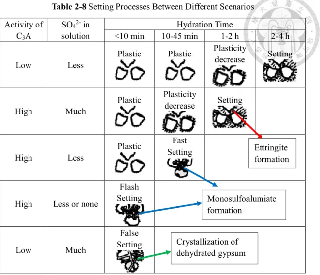
𝐶3𝐴 + 3𝐶𝑆̅𝐻2+ 26𝐻 → 𝐶6𝐴𝑆̅3𝐻32 (2-21) 2𝐶3𝐴 + 𝐶6𝐴𝑆̅3𝐻32 → 3𝐶4𝐴𝑆̅𝐻12 (2-22) Attention must be paid to the differences of setting caused by adding various amounts of gypsums. For example, scarcity of gypsum may cause flash setting, which hardens and releases a great amount of hydration heat in a short time. The setting processes between different scenarios of C3A activity and SO42- concentration is expressed in table 2-8.
Table 2-8 Setting Processes Between Different Scenarios Activity of
C3A
SO42- in solution
Hydration Time
<10 min 10-45 min 1-2 h 2-4 h
Low Less
Plastic Plastic Plasticity
decrease Setting
High Much
Plastic Plasticity
decrease Setting
High Less
Plastic Fast Setting
High Less or none
Flash Setting
Low Much
False Setting
Ettringite formation
Monosulfoalumiate formation
Crystallization of dehydrated gypsum
2-3-3 Properties of Harden Concrete
The properties of harden concrete are discussed in strength development and durability. Strength development especially compressive strength is the most important item for evaluating the concrete. Among all kinds of operation factors, composition of the reactant influents most significantly to the strength. When water is added, a set of chemical reactions named hydration occur between water and cement clinkers.
Gradually, the products of hydration began to fill in the void among the aggregates on the course of hydration, giving a solid block with high uniformity. As mention above, C3S hydrates more rapidly than C2S due to its unbalance of coordination, which results in the fact that C3S contributes strengths in both early and late ages while C2S is only responsible for long-age strength development.
Figure 2-8 Strength Development of Different Minerals in Clinker
Except the composition of reactant, other properties also have significant influence on strength. For instance, W/C ratio and porosity also have an adverse influence on strength. The empirical relationships raised by Powers between W/C, hydration degree
σ = 𝜎0[0.68𝛼 (0.32𝛼 +𝑊 𝐶⁄ ⁄ )]3 (2-23) where σ is the compressive strength of the cement paste, σ0 is the theoretical strength of cement paste without porosity, which is about 237 MPa, α is the degree of hydration, W/C is the weight ratio of water to cement.
Another equation of porosity to the compressive strength of cement paste is proposed by Rossler and Odler:
σ = 𝜎0(1 − 𝐸𝑃) (2-24) where E expresses the constant correlated to the porosity, P is the porosity of the paste.
Besides strength, durability also receives a great concern in modern cement industry. Factors which affect the durability of the concrete are listed in table 2-9. As this research is focused on the influence of adding carbonated alkaline wastes as mineral admixtures in the cement, only the free-CaO and free-MgO expansion, the sulfate expansion and the alkali-aggregate reaction are discussed in this section.
Table 2-9 Influenced Factors of Concrete Durability Abrasion Mechanical wear
Scour abrasion
Physical erosion
Freeze-thaw cycle Dry-wet cycle Water penetration Salt crystallization
Chemical erosion
Chemical medium
Hydrolysis Displacement Sulfate erosion Composition of
concrete
Alkali-aggregate reaction
Free-CaO and free-MgO expansion Reinforcement
erosion
Neutralization of concrete by CO2 in atmosphere Chloride ion in concrete