行政院國家科學委員會專題研究計畫 成果報告
新式陶瓷材料於可調式天線之應用 研究成果報告(精簡版)
計 畫 類 別 : 個別型
計 畫 編 號 : NSC 97-2221-E-011-021-
執 行 期 間 : 97 年 08 月 01 日至 98 年 07 月 31 日 執 行 單 位 : 國立臺灣科技大學電機工程系
計 畫 主 持 人 : 廖文照 共 同 主 持 人 : 周振嘉
計畫參與人員: 碩士班研究生-兼任助理人員:李威漢 碩士班研究生-兼任助理人員:王景平
報 告 附 件 : 出席國際會議研究心得報告及發表論文
處 理 方 式 : 本計畫涉及專利或其他智慧財產權,2 年後可公開查詢
中 華 民 國 98 年 10 月 12 日
行政院國家科學委員會補助專題研究計畫
■ 成 果 報 告□期中進度報告
新式陶瓷材料於可調式天線之應用
計畫類別:■個別型計畫 □ 整合型計畫
計畫編號:NSC 97 – 2221 – E – 011 - 021 執行期間: 97 年 8 月 1 日至 98 年 7 月 31 日
計畫主持人:廖文照 共同主持人:
計畫參與人員: 李威漢、王景平
成果報告類型(依經費核定清單規定繳交):■精簡報告 □完整報告
本成果報告包括以下應繳交之附件:
□赴國外出差或研習心得報告一份
□赴大陸地區出差或研習心得報告一份
■出席國際學術會議心得報告及發表之論文各一份
□國際合作研究計畫國外研究報告書一份
處理方式:除產學合作研究計畫、提升產業技術及人才培育研究計 畫、列管計畫及下列情形者外,得立即公開查詢
■涉及專利或其他智慧財產權,□一年■二年後可公開查詢 執行單位:國立台灣科技大學
中 華 民 國 98 年 10 月 12 日
1. 前言
回聲實驗室(Reverberation Chamber)亦稱為模態攪拌實驗室(Mode-stirred Chamber),能創造出複雜的電磁波傳播環境,可作為與電磁相容(Electromagnetic Compatibility)相關的測試場地,如待測設備(Equipment Under Test)之電磁波輻 射或耐受性測試,以及作為天線輻射效率的量測環境,該類實驗室可用來補足或 取代現在已經存在,並廣泛建置的方法,如開放區域測試地點(Open Area Test Sites)、(半)無反射實驗室(Semi/Anechoic Chambers)。特別是針對擁有複雜輻射 場型的電子儀器,回聲實驗室可提供更方便且經濟的量測方法。
2. 研究目的
本研究使用已知效率的參考天線與待測天線比對在回聲實驗室的傳播係 數,估計待測天線的輻射效率。從天線效率的實際量測與計算比對結果中,對於 低指向性的天線提供準確的效率估算。本研究針對微型天線,如晶片天線,開發 適合量測窄頻天線的回聲實驗室,量測低指向性天線的天線效率,具有簡易、經 濟又快速的優點。
3. 文獻探討
在 2003 年 8 月,回聲實驗室的技術已經被認證在 IEC 61000-4-21 的標準裡,
其中有設計上的指導方針。設計原則如:攪拌器的大小要佔有回聲實驗室內的一 定空間、攪拌器尺寸需相當於 LUF 的波長等[1]。除此以外,回聲實驗室的開發 過程,都要反覆地進行測試與除錯(Trial and Error),並可搭配合適的電磁模擬軟 體作分析,以符合規格要求。
回聲實驗室可視為一個大型的金屬共振腔,其體積要夠大才能提供夠多的 模態,且為一高度導電性的封閉腔。在形狀上,不是非常重要,然而它的體積相 當關鍵,能決定最低可使用頻率(Lowest Usable Frequency)。
金屬共振腔如果是矩形的形狀,每一邊的邊長要做成沒有比例性。一旦大 小固定之後,最低共振頻率 也就決定了。到 的三倍頻以上時,通常會有超過 60 種模態能夠存在。在模態夠多頻率下,除了在靠近金屬的地方,攪拌器轉動 時,可以讓大部分的位置都到一致的平均結果[2]。
品質因素(Q)是回聲實驗室好壞的一個重要指標,品質因素代表儲存能量 與消耗能量的比值,品質因素不能太高,金屬牆不能是完美導體,否則頻寬會很 小(BW=1/Q)。當 Q 值為無限大時,在單一操作頻率下,只能有一個模態可以存 在,能量無法耦合到其他非衰退模態[3]。然而 Q 值也不能太低,太低會讓各位 置的平均能量的一致性降低。品質因素與回聲實驗室關係密切[2]。而由於鋁的 導電率高,鋁可作為合適的回聲實驗室牆壁材料[4]。
4. 研究方法
本研究開發兩版回聲實驗室,在第一版回聲實驗室開發研究裡,主要是透過 改變環境中的相關參數,以實際量測的方式,來觀察並分析回聲實驗室的特性,
以及電磁波的反應狀況。依第一版回聲實驗室的量測結果,改良第二版回聲實驗 室的架構,並進行量測及結果觀察與比較;最後推導天線效率計算公式,並進行 計算比對。
第一版回聲實驗室(實驗室一)的金屬腔是由一體成型的不銹鋼鍋所組成,
如圖 1(a)。不銹鋼鍋的高度為 18 cm(不含蓋子),直徑為 26 cm,蓋子高度為 3.5 cm。蓋子上方鑽一個小孔,此孔是為了讓同軸纜線與風扇電源線的接頭可以進 入。孔的形狀是一個圓加上一個矩形,圓的直徑是 1.1 cm,矩型的長寬分別是 1.3 cm 與 3 mm。實驗室一中的電磁波攪拌器是一塑框風扇,尺寸為 12 cm × 12 cm × 3.8 cm,採用六段電子穩壓器供應其 12 伏電壓,如圖 1(b)。風扇的葉片上 貼滿銅箔貼紙,使風扇能反射電磁波,葉片轉動空間佔有 2.9 %的實驗室一空間 體積。
實驗室內的佈置上,風扇是站立於回聲實驗室的中央,發射與接收天線分別 放置於風扇的兩側。圖 1(c)為ㄧ保麗龍架,用來固定風扇與收發天線。第一版回 聲實驗室結構如圖 2 所示。
(a) 不銹鋼鍋
(b) 風扇與六段電子穩壓器
(c) 保麗龍風扇支架 圖 1 第一版回聲實驗室組成元件
圖 2 第一版回聲實驗室結構
在第二版回聲實驗室的設計上,我們提出多項設計改良。在空間上,採用較 大的共振腔。在傳播模態的攪動上,使用轉動速度較慢的轉台,在其上放置有空 間體積較大、較不規則、不對稱且更為立體的攪拌器,以攪拌電磁波傳播模態。
並將實驗室內部訊號佈線從上方蓋子進入,改到下方貼近地面的地方,讓同軸纜 線固定在同一個的位置,不會受到蓋子的開合而影響。
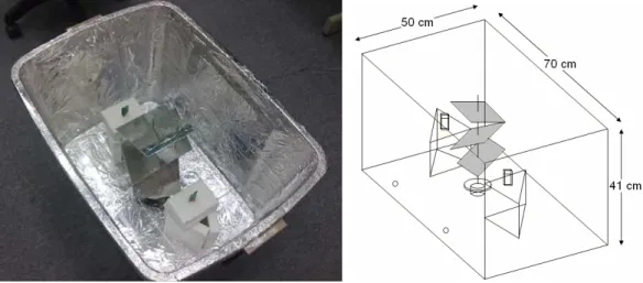
第二版回聲實驗室的元件包含實驗室牆壁、一個旋轉台、一支攪拌器、兩個 保麗龍架以及兩條兩公尺 Semi-rigid 同軸纜線。我們使用一只整理箱作為實驗室 的牆壁,箱子長、寬、高分別為 70 cm × 50 cm × 41 cm,並在內面貼上鋁箔,
如圖 3(a)所示。由於蓋子不平整,有許多凹槽,故先使用紙板填滿凹槽,再貼上 鋁箔。蓋子蓋上後,整理箱成為一個密閉的金屬共振腔。轉台的直徑為 8 cm,
高度為 4 cm,如圖 3(b)所示。轉台轉動 330°之後,再回轉,從 0°轉到 330°約花 13.78 秒。實驗室內部貼滿鋁箔紙的情形如圖 3(c)。在實驗室內部佈置上,我們 將轉台放置在實驗室的中央,在其兩側放置保麗龍架,用來架設收發天線。保麗 龍支架可以移動,其高度是箱子高度的一半,約為 20.5 cm。在左邊的架子上,
我們使用超寬頻單極晶片天線,當作發射天線。在右邊的架子上則放置另一支晶 片天線,當作接收天線。並將兩支天線以站立姿勢擺放,面對面且對稱的架設在 轉台左右側,兩者相距 36 cm。我們將天線面對面的姿勢定義為:「Face to Face」。
攪拌器由三片矩形葉片、一支細金屬柱與一個基座所組成,如圖 3(d)。我們 在矩形墊板上貼滿鋁箔紙,做成攪拌葉片,葉片尺寸為 21 cm × 15 cm。基座是 一個放置 CD 的架子,高度為 9 cm,圓底直徑為 14 cm,圓底厚度為 0.5 cm ~ 1 cm,中心柱直徑為 0.75 cm。金屬柱的直徑約為 0.15 cm。攪拌器的製作方式是 先將金屬柱固定在基座上後,再將三片矩形葉片擺放在金屬柱上,基座加上金屬 柱的長度為 34 cm。葉片設計上,每片都從上往下傾斜 50°,如圖 3(d)左圖。第 一片葉片中心靠在基座的最上方,第二片中心垂直往上移 10 cm,並在水平上旋 轉 80°,第三片中心則再往上移 10 cm,並旋轉 80°,旋轉方式如圖 3(d)右圖。
此示意圖為從上方往下看,箭頭代表葉片向下傾斜端,第二片相對位置為第一片 順時針旋轉 80°,第三片同上。當放上金屬棒放上葉片時,攪拌器總高度為 35 cm,葉片最頂端高出金屬柱約 1 cm,葉片最底端高出基座底約 5 cm。最後,將 攪拌器放置在實驗室內的轉台上,此時葉片最頂端距離蓋子 2 cm,葉片最底端 距離地面 9 cm。而葉片轉動空間,相當於第二版回聲實驗室的 7.9 %。
(a) 整理箱 (b) 轉台 (c)實驗室內部情況
(d) 攪拌器與擺設方式 圖 3 第二版回聲實驗室元件
在量測上,首先利用網路分析儀量測,網路分析儀掃瞄頻段為 2 ~ 7 GHz,
設定有 201 個資料取樣點,發射功率為 0 dBm。而平均次數需設定為 1000 次,
才能讓測量結果收斂,取 1000 次所花的時間為一分十二秒。第二版回聲實驗室 結構如圖 4 所示。
圖 4 第二版回聲實驗室結構
在已知參考天線的效率 之下,可以藉由個別量測出參考天線(Ref)與待測天線(AUT)在回聲 實驗室中的傳播係數S21,ref與S21,AUT,計算出待測天線的效率 。
2 21,AUT
AUT ref 2
21,ref
(3.10) e e S
S
= ×
因此我們把四種天線接收姿勢下所量測到的傳播係數作平均,可得到參考 天線與待測天線各頻率的傳播係數平均量值。再將此平均的傳播係數量值帶入 (3.10)後,則可計算出待測天線在 2.4、3.5 與 5.8 GHz 的天線效率,分別為 40.04、
66.13 與 88.04 %。表 3.6-1 為兩種效率計算方式的結果與實際量測結果的比較,
其中可以發現本節利用各姿態的傳播係數平均值來估算效率時,5.8 GHz 之高指 向性效率計算結果比先前採用移動平均的計算結果較為準確。而在 2.4 與 3.5 GHz,有低估的情形,以 2.4 GHz 的效率估算結果差異較大。
表 1 待測天線的兩種效率計算方式與實際量測結果比較
5. 結果與討論
在回聲實驗室的研究部分,由於現今個人無線通訊裝置發達,微型天線需 求多,使用量大。對小型天線而言,輻射場型與極化方向變得很不固定,輻射效 率是最為重要的考量參數。利用本研究之回聲實驗室做天線效率量測,可以在幾
分鐘之內,攪拌各個輻射方向與極化方向的電磁波能量,利用平均的方式,得到 最後的收斂結果。再以比對參考天線的方法,快速的估算出小型天線的輻射效 率,相較傳統的近場與遠場量測系統的掃瞄時程短相當多,而且回聲實驗室系統 成本亦便宜許多。日後,有機會成為一種普及的效率量測方法。
從回聲實驗室的開發工作裡,我們整理出以下七項主要的發現:
一、 攪拌器在回聲實驗室中所佔的空間比例越大,攪拌效果越好。
二、 攪拌器形狀越不規則,越能增加傳輸路徑種類,達成傳輸量的一致性。
三、 天線反射係數會受到實驗室影響,故天線不能太靠近牆壁。
四、 天線指向性越高收斂性越差,指向性可能會影響攪拌結果,讓回聲實驗室 內的傳播不易達成一致性。
五、 攪拌器起始位置不同之下,做攪拌並平均,最後能使 S21 呈現一致的量值,
這表示攪拌器確實有攪拌作用,即便起始的模態不同,最後都能將接收能量攪拌 到一個定值。
六、 攪拌器轉動之下,做能量的平均以後,S 參數變動的幅度有縮小一些,這 代表攪拌器有攪拌能量,讓量值平均的效果。
七、 發射功率太小或太大會超出儀器的使用範圍,故要操作在中間的量值,以 免造成量測誤差。
參考文獻
[1] IEC, IEC 61000-4-21-Electromagnetic Compatibility (EMC)-Part 4-21: Testing and Measurement Techniques-Reverberation Chamber Test Methods, International Electronical Commission (IEC), Geneva, Switzerland Int. Std., CISPAR/A and IEC SC 77B, 2003.
[2] W. J. Krzysztofik, and S. Wolny, “Design of small reverberation chamber for handsets testing,” Microwaves, Radar and Wireless Communications, 2008.
MIKON 2008. 17th International Conference, pp. 1-4, 2008.
[3] C. Bruns, and R. Vahldieck, “A closer look at reverberation chambers - 3-D simulation and experimental verification,” Electromagnetic Compatibility, IEEE Transactions, vol. 47, no. 3, pp. 612-626, 2005.
[4] J. F. Rosnarho, Mode-stirred Reverberation Chamber Testing, Interference Technology Annual EMC Guide, Siepel, La Trinite-sur-Mer, France, 2004.
[5] H. W. Liu, C. F. Yang, S. T. Lin, and C. L. Hu, “A planar chip antenna for UWB applications in lower band,” in IEEE AP-S Int. Symp. Dig., Honolulu, Hawaii, pp.
5147-5150, 2007.
計畫成果自評
以下就研究內容與原計畫相符程度、達成預期目標情況、研究成果之學術或應用 價值、是否適合在學術期刊發表或申請專利、主要發現或其他有關價值等,作一 綜合評估。
一、研究內容:
本研究開發兩版回聲實驗室,在第一版回聲實驗室開發研究裡,主要是透過 改變環境中的相關參數,以實際量測的方式,來觀察並分析回聲實驗室的特性,
以及電磁波的反應狀況。依第一版回聲實驗室的量測結果,改良第二版回聲實驗 室的架構,並進行量測及結果觀察與比較;最後推導天線效率計算公式,並進行 計算比對。
二、達成目標:
從天線效率的實際量測與計算比對結果中,顯示所開發的回聲實驗室對於低指向 性的天線可提供準確的效率估算。本回聲實驗室適合量測窄頻且指向性低的天線 效率,具有簡易經濟又快速的優點。
三、學術及應用價值:
由於無線通訊中的手持式設備增加,微型天線需求變大。利用傳統之遠場與近場 量測系統來量測小型天線效率,並不方便、且昂貴費時。因此利用本研究開發的 回聲實驗室進行天線效率評估,可使用簡單的功率量測儀,採取一邊攪拌電場,
一邊取平均的測量方式,省去同步測量的機制,僅花費幾十秒即可讓量測值收 斂。兼具學術的創新性與產業的利用性
四、期刊發表:
本案所發展之回聲實驗室在小型天線的天線效率量測及準確度評估結果與分 析,將於整理後,投稿期刊發表。
五、主要發現:
利用本研究之回聲實驗室做天線效率量測,可以在幾分鐘之內,攪拌各個輻射方 向與極化方向的電磁波能量,利用平均的方式,得到最後的收斂結果。再以比對 參考天線的方法,快速的估算出小型天線的輻射效率,相較傳統的近場與遠場量 測系統的掃瞄時程短相當多,而且回聲實驗室系統成本亦便宜許多。日後,有機 會成為一種普及的效率量測方法。
An Antenna Efficiency Assessment Method using Reverberation Chamber
#Wen-Jiao Liao 1, Ching-Ping Wang 1
1 Department of Electrical Engineering, National Taiwan University of Science and Technology No. 43, Sec. 4, Keelung Rd., Taipei, Taiwan, [email protected]
1. Introduction
Due to the growing popularity of personnel mobile communication devices, miniaturized antenna designs are in great demands. However, as the antenna size gets smaller, the input reactance gets larger and the antenna efficiency dwindles as well. Furthermore, conventional antenna performance parameters, such as directivity and polarization, become less apparent since the antenna behaves more like an isotropic radiator. Therefore, it is not quite convenient to measure the antenna characteristics using a traditional far-field chamber. The near-field chamber, on the other hand, is capable of evaluating the antenna efficiency by sampling the radiated power on a spherical grid enclosing the antenna. Nevertheless, the measuring process is time consuming and required relatively expensive equipment. In order to evaluate the antenna efficiency, which is the most critical radiation feature for a small antenna, we proposed a time and cost effective measurement method based on the reverberation chamber (RC) configuration.
Unlike conventional far-field or near-field chambers, which attempt to measure the antenna radiation properties in an emulated “free space” environment, the electromagnetic reverberation chamber is a resonant cavity that is rich in propagation paths. The numerous modes of the reverberation chamber provide a more rigorous platform to examine an electronic device with a complex radiation pattern. The reverberation technique is therefore getting more popular for EMC tests and is included in IEC 61000-4-21 standard [1]. An overview and discussion on many aspects about the measurement and simulation of reverberation chamber is provided in [2].
The reverberation chamber technique, which is widely accepted for EMC/EMI testing, is also considered for small antenna performance assessment. Although the RC technique can’t supply radiation pattern information, the antenna radiation efficiency can still be revealed via statistical measures providing that the field uniformity is achieved. The RC technique is particularly attractive for its low cost since no absorber is needed. Via simulations, Krzysztofik and Wolny show that unlike EMC reverberation chamber, which requires an electrically large environment, the chamber size can be greatly reduced for small antenna measurements [3]. In [4], the RC technique is compared with the Wheeler cap method for small antenna radiation efficiency. The measurements on UWB antennas are conducted in [5].
In this work, a small reverberation chamber is implemented to evaluate the efficiencies of small multi-band antennas. Instead of recording transmission levels at different stirrer positions, we attempt to estimate the efficiency based on the averaged level of various stirrer orientations to eliminate stirrer control part. Section 2 describes the formulation of the chamber and the test antennas used. Section 3 presents the derivation for antenna efficiency calculation. In Section 4, efficiency estimations based on RC measurements are compared with efficiencies measured in spherical near field chamber. A short summary is given in the end.
2. Reverberation Chamber Setup
The prototype reverberation chamber was made with a plastic container of 70×50×41 cm.
Aluminium foil was laid inside the container and its lid as shown in Fig. 1(a). Two antenna stands made of Styrofoam and a stirrer mounted on a battery powered rotating display stand were placed within the container as indicated in Fig. 1(b). The stirrer height including its mount is 39 cm including and its diameter is 22 cm.
Two antennas, as shown in Fig. 2, were used for antenna efficiency evaluation. One is an
chip antenna can operates between 3.3 to 6.3 GHz, while the monopole antenna covers the 2 to 7 GHz band. The two antennas were measured in a 3-D spherical near-field chamber to find their gains and efficiencies as tabulated in Table 1. According to the measurement results, we noted that the chip antenna is not quite efficient at 2.4 GHz and the monopole antenna is somewhat directive at 5.8 GHz.
(a) Fabricated reverberation chamber (b) Reverberation chamber schematics Figure 1: The implemented reverberation chamber for small antenna efficiency estimation.
(a) UWB chip antenna (b) Monopole UWB antenna Figure 2: Antennas used for antenna efficiency assessment.
Table 1: Antenna efficiencies and gains measured in spherical near field chamber.
UWB chip antenna Monopole UWB antenna Frequency
(GHz) Gain (dBi) Efficiency (%) Gain (dBi) Efficiency (%) 2.4 1.41 28.48 1.28 90.09 3.5 3.50 74.89 2.66 81.88 5.8 2.77 70.58 6.19 82.85 We next examined the reverberation chamber’s field uniformity by setting the stirrer in different starting orientations. Measurements were taken by a network analyzer with continuous frequency sweeping and averaging operation. The stirrer is continuously rotating during the measurement process and the stirrer takes about 13.78 seconds to complete one rotation. Fig. 3 shows the averaged spectra of three measurements. Each measurement contains 1000 trails. The S11 spectra are almost identical while the S21 spectral are similar in general.
3. Antenna Efficiency Calculation
Considering the radiation and propagation mechanisms taking places within the reverberation chamber, the antenna efficiency can be estimated as follows. The power transmitted to the other antenna within the reverberation chamber is |S21,AUT|2, which can be written as the serial sum of the power goes into and out of the receiving antenna due to mismatch. The Ohmic losses
incurred within the reverberation chamber side walls are represented by LossRC. The antenna efficiencies of transmitting and receiving antennas are abbreviated as eref and eAUT, respectively.
S11,free and S22,free refer to the mismatch measured in free space.
) 1 (
) 1
(
|
| 1
)
|
| 1 ( ) 1
( )
|
| 1 (
...
)
|
| 1 ( ) 1
(
|
| )
|
| 1 (
)
|
| 1 ( ) 1
( )
|
| 1 (
|
|
2 , 22
2 , 22 2
, 11
2 2 , 22 2
2 , 22 1 2 , 11
2 2 , 22 1
2 , 11 2
, 21
RC free
free RC
AUT ref free
free RC
free free
free RC
free AUT
Loss S
S Loss
e e S
e S
Loss S
e S
e S
Loss e
S S
−
⋅ +
⋅
−
⋅
−
⋅
⋅
⋅
= −
+
⋅
−
⋅
−
⋅
⋅
⋅
−
+
⋅
−
⋅
−
⋅
⋅
−
=
When two identical reference antennas are used for both transmitting and receiving sides, above transmission level becomes
) 2 ) (
1 (
|
| 1
)
|
| 1 ( ) 1
( )
|
| 1
| (
| 2
, 11
2 , 11 2
, 2 11
, 21
RC free
free RC
ref ref free
ref S Loss
S Loss
e e S S
−
⋅ +
⋅
−
⋅
−
⋅
⋅
⋅
= −
since the S11,free and S22,free are the same. By dividing Eq. (1) by Eq. (2), the ratio of transmission level of AUT and reference antenna is
) 3 )] (
1 (
|
| 1 [ )
|
| 1 (
)]
1 (
|
| 1 [ )
|
| 1 (
|
|
|
|
2 , 22 2
, 11
2 , 11 2
, 22 2
, 21
2 , 21
RC free
ref free
RC free
AUT free
ref AUT
Loss S
e S
Loss S
e S
S S
−
⋅ +
⋅
⋅
−
−
⋅ +
⋅
⋅
= −
By assuming S11,free and S22,free are small in operation bands, Eq. (3) can be further reduced to eAUT = eref×|S21,AUT|2/|S21,ref|2.
(a) UWB chip antenna (b) Monopole UWB antenna Figure 3: Averaged S parameters of three measurements in the reverberation chamber.
4. Results
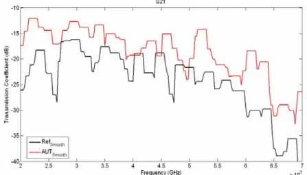
The antenna efficiency can be calculated from S21 results measured in the reverberation chamber by applying the efficiency relationship derived above. In principle, the antenna efficiency, though is a function of frequency, is relatively stable near the resonant band. However, we note that the measured S21 spectra are quite volatile due to spectral variation in cavity modes. The difference can be as large as 30 dB due to constructive and destructive addition among propagation of different paths. Therefore, to ensure received power is not disguised by multiplath cancellation, we took the moving average in the frequency domain by using just the maximum transmission level values among 7 neighbouring samples. Because the frequency domain resolution is 25 MHz, we can assume antenna radiation efficiency is consistent over the 150 MHz band. The smoothened spectral of the two antenna are shown in Fig. 4. Using the chip antenna as the reference antenna and the monopole as AUT, the calculated efficiencies of AUT at three different bands are tabulated in Table 2. Note that the errors are less than 12% for 2.4 and 3.5 GHz results, while the estimated efficiency at 5.8 GHz is too high. This may be caused by the high directivity of monopole antenna at 5.8 GHz so that the reverberation chamber field uniformity is not satisfied.
5. Conclusion
In this work, an antenna efficiency measuring apparatus was devised based on reverberation chamber configuration. Amounts of transmission from reference antenna to AUT are recorded in a shielded box with various stirrer orientations. Measurement results show that the transmission value converges when enough samples are averaged. By comparing with the result of a known reference antenna, the AUT antenna efficiency can be addressed. Measurement results indicate that the proposed method yields good satisfying results for narrow band isotropic radiator, the differences to near-field results are around 10%. The proposed method is simple, quick and economically attractive. The “reverberation chamber” used here is relatively small. The convergence is achieved in tens of seconds. Furthermore, no synchronization mechanism is required for the instrument and the stirrer rotation. Future work topics include error reduction and adaptation for its uses on broadband antennas.
References
[1] IEC 61000-4-21-Electromagnetic Compatibility (EMC)-Part 4-21: Testing and Measurement Techniques-Reverberation Chamber Test Methods, International Electronical Commission (IEC), Geneva, Switzerland Int. Std,. CISPAR/A and IEC SC 77B, Aug. 2003.
[2] C. Bruns, R. Vahldiecj, “A closer look at reverberation chambers-3-D simulation and experimental verification”, IEEE Trans. on Electromagnetic Compatibility, vol. 47, No. 3, pp.
612-626, 2005.
[3]A.A.H. Azremi, H.G. Shiraz, P.S. Hall, “Small antenna rfficiency by the reverberation chamber and the wheeler cap methods”, 13th IEEE International Conference on Networks, vol. 1, pp.
12 – 16, 2005.
[4] W.J. Krzysztofik, S. Wolny, “Design of small reverberation chamber for handsets testing”, International Conference on Microwaves, Radar and Wireless Communications, 2008.
[5] A. Sharaiha, P. Besnier, G. Le Fur, “Efficiency measurement of UWB small antennas in reverberation chambers”, European Conference on Antennas and Propagation, 2007.
Figure 4: Moving Average of S21 spectra of reference and AUT antennas.
Table 2: Comparison of antenna efficiencies measured from near-field chamber and estimations from reverberation chamber.
Frequency (GHz)
Measured efficiency (from spherical near-field chamber)
Estimated efficiency (from reverberation chamber measurement)
2.4 90.87 79.8
3.5 81.88 80.0
5.8 82.85 137.7
出席國際學術會議心得報告
計畫編號 NSC 97 – 2221 – E – 011 – 021
計畫名稱 新式陶瓷材料於可調式天線之應用 出國人員姓名
服務機關及職稱 廖文照助理教授,國立台灣科技大學電機系 會議時間地點 98 年 3 月 23 日至 98 年 3 月 27 日於中國北京市
會議名稱 Progress In Electromagnetics Research Symposium 2009
發表論文題目
1. A multi-layer coupled-line power divider
2. Evaluation of scattering in collision avoidance radar application 3. Propagation of ultra wideband signals in automotive environment
一、參加會議經過
本人自 98 年 3 月 22 日啟程抵達中國北京市,在完成登記後,與會場間先前熟識的 各國教授與合作人員交換研究近況與心得。於 23 日到 27 日間主要參加下列幾個 session:
1P7 Electromagnetic Field in Materials and EM Field Dispersion in Cloaks and Photonic Crystals.
2A3 Synthetic Aperture Radar and Its Applications 1.
2P2 Metamaterial Technologies from Microwave to Optics.
3A2a Metamaterial Applications: from Antennas to Cloaking.
3P1 Mathematical and Numerical Tools for Metamaterials 2.
4A7 MIMO, DOA and Wave Propagation in Wireless Communication 4P3 Remote Sensing, GPR, SAR
5A5a Microwave Circuits and Systems
本人並分別於 26 日及 27 日在 Session 4A7、4P3 及 5A5a,發表”A multi-layer coupled-line power divider”、”Evaluation of scattering in collision avoidance radar
application”、”Propagation of ultra wideband signals in automotive environment”等三篇論文 報告,在 Q&A 時段,有多位聽眾提問,並交換聯絡方式,持續進行意見交換。
二、與會心得
這一次參加 PIERS 會議,主要參加的 session 是集中在新型材料與結構及其射頻上 的應用,對於該領域的新進發展,有了更進一步的認識。對於我在本計劃與後續計畫中 利用新式陶瓷製作特性可電子控制的天線型式,也提供了多個發展方向上的指引與技術 上的啟發。