Optimal Control of an Under-Actuated System for
Landing With Desired Postures
Eileen Chih-Ying Yang, Paul C.-P. Chao, and Cheng-Kuo Sung
Abstract—Control over landing posture can effectively prevent structural damage when a portable device is accidentally dropped. Given size and cost constraints, the number of actuators should be limited. This paper presents an optimal posture control method that allows an under-actuated system to land with the desired pos-ture. A simplified model of a portable computer/telephone is con-sidered, comprising two rigid bodies and an active joint. The ob-jective is to minimize the input torque produced by the actuator to achieve the desired posture. A two-point boundary value problem is formulated; i.e., the initial and final angular positions and veloc-ities are predetermined, and the inequality constraints are estab-lished on the basis of the capacity of the actuator and acceptable level of state variables. In the numerical analysis, the backward-sweep algorithm is applied to determine the appropriate Lagrange multiplier, and the falling dynamics are explored usingMATLAB. The optimal controller design is presented, together with simula-tion results confirming that the system is capable of performing landing posture control with minimum input torque.
Index Terms—Nonlinear dynamics, posture control, under-actuator.
I. INTRODUCTION
S
MALL dimensions portable electronic devices, such as cellular phones, are more prevalent in recent years. How-ever, the unpredicted falling of cellular phones often occurs during common operation, and the fatal damage is usually caused by an impact at the landing instant. Therefore, raising the strength against impact damages is one of the most impor-tant design specifications for electronic devices. In general, the impact defense of electronic equipment is achieved by en-hancing strength of the structure or by adding energy-absorbing material in fragile domains. The related works [1]–[4] have been focused on framework improving to absorb the energy caused by the drop, i.e., altering geometry design at partic-ular locations or adding damping materials is the widespread solution for guarding structural integrity while impacting theManuscript received March 05, 2009; revised November 06, 2009; accepted March 05, 2010. Manuscript received in final form March 23, 2010. First pub-lished April 22, 2010; current version pubpub-lished February 23, 2011. Recom-mended by Associate Editor P. Meckl. This work was supported by the National Science Council of R. O. C. under Contract NSC 97-2221E-007-050-MY3, and Contract NSC 97-2221-E-009-085-MY3.
E. C.-Y. Yang and C.-K. Sung are with the Department of Power Mechan-ical Engineering, National Tsing Hua University, Hsinchu 300, Taiwan (e-mail: [email protected]; [email protected]).
P. C.-P. Chao is with the Department of Electrical and Control Engineering, National Chiao Tung University, Hsinchu 300, Taiwan (e-mail: pchao@mail. nctu.edu.tw).
Color versions of one or more of the figures in this paper are available online at http://ieeexplore.ieee.org.
Digital Object Identifier 10.1109/TCST.2010.2046902
ground at falling. It is called “passive” impact defense. The magnitude of the stress occurred at the impacted region depends on the falling conditions, such as height, releasing postures, and initial velocity. However, the passive landing control may not function adequately for various falling conditions that are incalculable in nature. This study intends to provide an active posture control scheme to allow the twin-body system impacting the land with the desired posture.
This idea originates from the well-known falling cat problem [5]–[7]. The dynamics of this problem is regarded as that with nonholonomic constraint. Chen et al. [5] established the dy-namic equation by the condition of zero angular momentum. Weng et al. [6] used final-state control to compute the input torque for the cat robot. The cat robot had been created by Kawamura et al. [7]. For similar investigation about posture control, Agrawal et al. [8], [9] proposed the design of a hovering vehicle with biaxial rotation and motion control resembling that of a planar biped.
The authors considered a 2-rotational-degrees-of-freedom (DOFs) twin-body system, which is in fact a particular cellular phone model consisted of two rigid bodies and an active joint with two relative DOFs [10]. Corresponding with these two DOFs, two actuators are employed to provide orthogonal torques to realize the inclination between two bodies and rotation through self-axis, respectively. The desired landing postures were achieved by employing computed torque method, PD control, and sliding-mode control. However, these con-trollers only controlled two DOFs of the dynamics, the relative angular positions between two bodies; while the contacting point during the landing instant was not controlled.
In this study, optimal control is applied to achieve landing with the desired posture or impact point/region, and the ob-jective of optimal control is to minimize the input torque. In addition, two-point boundary conditions of the system should be considered, and they consist of three parts: 1) the initial angular positions and velocities, which are defined according to the falling conditions; 2) the final angular positions of the L-body, which determine the point/edge/face subjected to the landing impact; 3) all the final angular velocities, which influence the impact energy at the landing instant. A controller with three input torques is generally adopted to satisfy these constraints at the landing instant, which are three angular positions and five angular velocities. However, an active joint having three orthogonal torques is typically too complex to be installed in a portable device. In addition, a system with three rotational DOFs will have a larger coupling force/torque, which will cause the system to be uncontrollable, and the control input would increase to cancel the coupling effect [11].
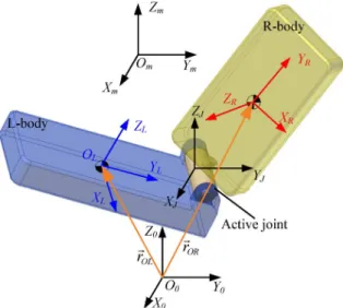
Fig. 1. Model of a twin-body system, five coordinates (X Y Z , X Y Z , X Y Z , X Y Z , and X Y Z ) and two vectors (~r and~r ) applying into deriving the dynamic equations.
Herein, we attempt to control the system using only two input torques, and this system constitutes to an under-actuated con-trol problem. The optimal concon-trol is adopted to minimize the input energy, and it can be categorized into a two-point boundary constraint optimal problem. To solve the control problem, the kinematics of the twin-body system is first established with five coordinates and Euler angles, and the equations governing the dynamics of twin-body system are derived based on the La-grange–Euler formulation. The necessary equations of optimal control programming are then constructed according the con-trol objective and constraints. The backward-sweep algorithm is adopted to obtain the optimal control gain in numerical analysis, and the system dynamics are expressed using MATLAB
simula-tions. Accordance with simulations, the optimal control is fea-sible for the landing with desired posture of the under-actuated system.
II. PHYSICALMODEL ANDDYNAMICS
The twin-body system representing a cellular phone with two relative rotational degrees of freedom (RDOFs) is illustrated in Fig. 1. It consists of two identical rectangular rigid bodies and a two-RDOF active joint connecting them. For convenience of the ensuing analysis, one of the bodies is named “R-body,” while
another is “L-body.” Herein, the dimensions and materials of the two bodies are assumed the same for the sake of simplicity. The relative motions between the two bodies can then be realized by installing two orthogonal motors to offer actuating torques along two RDOFs.
Fig. 1 shows notations for the coordinate systems of the two-body system. Five sets of Cartesian coordinates are defined. Two coordinate systems are parallel to the ground coordinates : 1) the joint coordinates with origin fixed to the rotational center of the joint and 2) the mass center coor-dinates with origin at the combined mass center of the twin bodies. The origin moves due to gravity,
, and external force, . In this paper, the system is cogitated as free fall , the linear motion of can be formulated as . The other two coordinates are body-fixed ones: 1) the L-body coordinates with origin fixed to the mass center of the L-body and 2) the R-body coordinates with origin fixed to the mass center of the R-body. The -, -, and -axis of R-and L-body coordinates are considered as the direction along the width-, length-, and thick-edge of bodies, respectively.
In this paper, we assume that the free-falling is ideal, which indicates, during falling process, the gravitational force only causes the mass-center coordinate system falling along -axis. Therefore, we consider the posture variation of the system based on the rotational motions, and the height
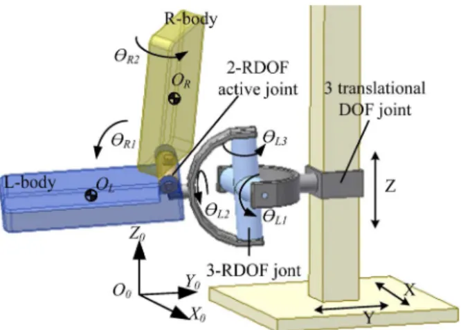
is considered by the elapse time ( , is the initial height). For describing the rotational motions of the system, five Euler angles, , , , , and , are defined as shown in Fig. 2. L-body moves in three rotational DOFs, , with respect to joint coordinates, and they are defined in accordance with 123-Euler angle, i.e., they rotate respectively through -, -, and -axis. Two angles defined as the relative angles between two body coordinates are captured by and , and they rotate about - and -axis. Based on the aforementioned definition, the transition matrices of these coordinates can be written as shown in (1)–(3)
at the bottom of the page, where , ,
, and .
Equations of motion are derived following the standard procedure of robotic modeling, which starts with considering the twin-body system as one of robot manipulators and then applying Lagrange–Euler formulation [12]. In this way, the robot manipulator of the model in Fig. 2 has three links: one
(1) (2)
Fig. 2. Equivalent manipulator of twin-body system.
virtual link, which is massless and inertialess, and two realistic links. The virtual link, link-J, is defined as the point , and the two realistic links are L-body and R-body. There are three joints connecting links: 1) a 3-translational-DOF joint, con-necting the ground and Link-OJ; 2) 3-rotational-DOF one, the link and L-body; and 3) a 2-rotational-DOF one, L-body and R-body. Based on the previous definitions of coordinates, the vector , from point to point and observed in ground coordinates, and the vector , from point to point and observed from ground coordinates, can be written as
(4)
(5)
where , , and are the initial positions of the ob-served from ground coordinates; is the length of bodies; is
the gravity. The mass center velocity and acceleration of two bodies are the first and second derivatives of the above, that is
(6) Based on previous definitions of rotation angles, the angular ve-locities of two bodies can be written as (7) and (8) shown at the bottom of the page. From basic dynamics, the total kinetic and potential energy can be written as
(9) (10) where is the body mass; and are the moments of inertia of the two bodies. Based on Lagrange–Euler formulation, the Lagrange’s equation can be written as
(11)
where ; ;
, and and are the input torque via the active joint, which are along - and -axis. From (11), the dynamic equations can be described in matrix form as
(12) where is the state variables and is defined as
; is a 5 1 input torque vector , and is the input torques via the active joint, which are along - and -directions of the L-body coordinates. is the inertial matrix (the coefficient of the angular accelerations), a 5 5 positive definite matrix. More-over, is a function of angular position, and it will vary with postures. is the nonlinear term of dynamic equations, which includes the centripetal and Coriolis force (i.e., , and ). is decoupling damping matrix, a 5 5 matrix, and it is the remnant term of the angular velocity coefficient excluding nonlinear parts. Nevertheless, the detail term of these matrices are too complex that we can show in this paper. The system is
(7)
obviously nonlinear and can be described by a second-order differential equation with nonholonomic constraints.
III. OPTIMALCONTROL
In this study, the landing postures are considered in ac-cordance with controlling angular positions and velocities of the system, i.e., are controlled to achieve the desired landing posture. However, there are only two in-dependent input torques produced by adopted actuator. The number of input torque is less than the number of control variables. The twin-body system can be categorized into a mul-tiple-input–multiple-output (MIMO) under-actuated nonlinear mechanical system [13]. For this class of control problems, some previous researches focused on a 3-DOF robot with a passive joint [14], [15]. Herein, the optimal control problem is to minimum input torque and constrained by two-point boundary conditions. In other words, the optimal performance index is defined in accordance with the initial/final conditions, and the actuator capacity. To apply the optimal control, we take the angular positions and velocities as the state variables, and the equations of the state variables can be rewritten from (12)
(13) Since the difference in magnitude of variables is about ( ; ), non-dimensionalization during op-timal programming has been adopted to deal with the problem during optimal programming. The non-dimensional angular po-sitions and time are denoted as and , respectively, and they are defined in the following equations:
(14) (15) where symbolizes the input-torque capacity of the actua-tors, and and are defined as
(16) (17) where and are the mass and length of bodies. According to the aforementioned definitions, the first and second differentials of the non-dimensional angular positions are established as
or (18)
or (19)
The dynamic equations [see (12)] can then be rewritten in a non-dimensional form (20) where (21) (22) (23) For the present twin-body system, we denote the non-dimen-sional state variables as , and the state equations of the system can be rewritten as
(24)
(25) Next, the two-point boundary conditions are defined ac-cording to the initial and final conditions. The initial and final condition denoted by the suffix of and , separately, and they are described as
(26) (27) where is the initial time in non-dimensional; and , are initial angular positions and velocities; and , are final an-gular positions and velocities. The control outputs consist of: 1) the angular positions , to designate the impact point or region at landing instant and 2) the angular velocities , to reduce the impact energy (that would be decreased if the angular velocities approach zero). The desired outputs can be written in (28)
(28) where the desired outputs are defined with the suffix . The con-straint functions of the final state with prescribed values can be described as the function of the condition at the landing instant, and it is written as
(29) In addition, the inequality constraint equations are defined ac-cording to the capacity of the input torque , and it is written as
(30) The objective of the optimal control scheme is to minimize the input energy, and the optimal performance index is com-posed of three factors: 1) the time-invariant equality constraints at , ; 2) the acceptable level of the angular po-sitions and velocities, , as inequality constraints; and 3) the input energy, . The last two factors are time-varying, and they should be considered for integration from to with
an optimal performance index . From the aforementioned de-scription, the optimal performance index , which is expected to be minimized during the falling process, can be formulated as
(31)
where and are both positive semi-definite matrices and is a positive definite matrix. The components of the matrices are optimal design parameters and are chosen according to the acceptable levels of , , and .
In this optimal control problem, the Hamiltonian equation are defined by using the Lagrange multiplier to incorporate the dy-namic constraint
(32) where is a 10 1 vector of the Lagrange multiplier. The differential equation of the Lagrange multiplier can be given as
(33) When considering the final condition, the other Lagrange mul-tiplier vector is adopted, and the equation can be written as
(34) The input torque can be computed from the following algebraic equation which is established on the basis of the optimal control law:
(35) From the above equations, the necessary functions of optimal programming [(25), (26), (29), and (33)–(35)] are completely established. The optimal solutions can then be obtained using a numerical analysis.
IV. NUMERICALANALYSIS
In numerical analysis, we adopt the backward-sweep algo-rithm [16] to obtain an exact vector, and solve the input torques and stable variables using the necessary functions. The dynamic analysis of the twin-body system with optimal control is per-formed using MATLABsimulation. In this paper, the mass and geometric properties for each body were selected to resemble objects roughly the size of a cellular phone. We consider the in-ertia ( and ) in (9) as the value which is similar to the cel-lular phone, and the input toque would be limited the capability of actuators installed on the cellular phone in accordance with
TABLE I
INITIALSTATES ANDDESIREDOUTPUTS OFSIMULATIONS
modulating the variable in (31). In addition, the feedback in-formation including angular position and velocity can be mea-sured by a three-axis accelerometers fixed on L-body and two encoders built on motor.
Liquid crystal displays and rotational joints are the more fragile parts, and they will suffer from irreparable damages after landing on the ground. In practical applications, the system can be provided with protection against landing impacts by making it landing with desired postures. Based on the optimal control, many falling condition can be controlled to avoid impacting with fragile parts. However, some falling-conditions are uncon-trollable under this optimal control, since the posture control represents an under-actuator control system, in which the number of inputs is less than the number of outputs. The exact control variables for some cases cannot be found in simulation. For example, when the initial or process conditions are around to the singular posture, the under-actuator controller cannot be applied to change the posture. The input torque cannot change the angular position/velocity observed from the ground (i.e., ), sine the input torque and these three DOFs are decoupled in singular posture.
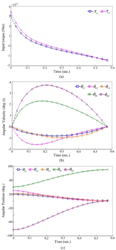
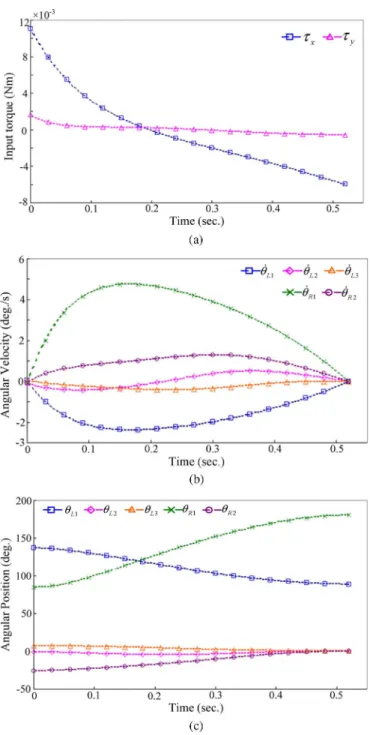
In general, the cellular phone is full-open condition during calling, and bent while terminating. Therefore, we choose these two falling condition, which often occurred for the unexpected falling of cellular phone, to verify the feasibility, and these two cases are away from singular posture. In Case 1, we imitated the condition of full-open operation at 1.5 m height, and the desired posture such that the impact is on the larger area of the cellular phone battery. In Case 2, we assumed the condition that the cell phone is already bent and on the way falling to the crash surface from 1.3 m, and the desired landing posture is considered as closed postures and landing on the edge without an active joint. Table I illustrates the initial state variables, desired outputs and corresponding postures of simulations.
To simplify this problem, in simulations, we consider the two bodies to be identical, and the inertias of a body through three directions are also defined to be identical, i.e.,
kg-mm . Since we expect the posture control to be applied to unexpected falling from a height of 1.5 and 1.3 m, the time period in MATLABsimulations is considered to be 0.57 and
TABLE II
PARAMETERSDEFINITION FORTHREECASES
TABLE III
VARIABLESDEFINITION FORTHREECASES
0.52 s. and represent the non-dimensional parameters, whereas and represent the optimal design parameter ma-trices and are chosen in accordance with the acceptable level of and . These four parameters are defined to be identical and are given in Table II. and are the optimal design variables and are shown in Table III. Figs. 3 and 4 show the simulation results.
The control system changes the posture to become the desired landing posture, and the angular velocities of all DOFs become very close to zero at the final time, thereby reducing the im-pact energy. The feasibility of the optimal control law applying to posture control is verified in accordance with above simula-tions. Nevertheless, the optimal control has some disadvantage to realize the control system.
The fatal defect of the optimal control is that the Lagrange multiplier is not easily determined, and the variables need to reset for each case. To search the exact Lagrange multiplier , the initial values should be supposed to begin the backward-sweep algorithm. Then, the finial condition can be derived in ac-cordance with the supposed values, and the difference between finial and desired condition is calculated. Based on the differ-ence, adopted in next circle is considered, and the is repeat-edly revised until the final condition approach to the desired one. However, the unsuitable initial value would cause the con-dition of the system to pass through the singularity or to ap-proach infinite angular position/velocity. That would cause the expected to diverge the exact value in backward-sweep algo-rithm. In addition, the Lagrange multiplier is an 8 1 vector, and the eight initial values all need to choose appropriately. It is a difficult assignment. Therefore, the Lagrange multiplier is not foraged easily for this optical controller applied in posture control. In addition, the height for on operating a cellular phone is usually about 1.3 1.8 m, and the damage may occur when it falls from a position higher than 0.5 m. Since no sensors can directly measure the dropping height, we estimate the critical height that the damage may occur and then design the actuator and controller that can certainly achieve desired postures before landing.
In the optimal control, the input torques provided by the ac-tive joint cause the relaac-tive angular positions and velocities be-tween two bodies, i.e., , , , and . Nevertheless,
Fig. 3. Simulation results of Case 1: (a) input torque; (b) angular velocity; (c) angular position.
the conditions of the L-body, , , , , , and , are affected by the coupling force/torque in accordance with the angular momentum conservation. These simulations verify that the conditions of the L-body can be controlled to achieve the desired condition by using the input torques if the condition is away from singular conditions. The controller with two input torque can successfully control the conditions of the L-body, including three angular position and three angular velocities. Moreover, the optimal control law can be applied to the pos-ture control of under-actuated systems.
Fig. 4. Simulation results of Case 2: (a) input torque; (b) angular velocity; (c) angular position.
V. CONCLUSION
This study is dedicated to achieve landing posture control of an under-actuated system, and the objective is to control the pos-ture of accident falling at landing instant. In choosing the de-sired landing posture, we consider that liquid crystal displays and rotational joints are the more fragile parts, and they will suffer from irreparable damages after landing on the ground. The system can be provided with protection against landing im-pacts by making it landing with desired postures. We adopt two desired postures to illustrate the feasibility of the optimal con-troller design. From simulations, the control system changes the
posture to become the desired landing posture before landing instant, and the angular velocities of all DOFs are very close to zero at the final time to reduce the impact energy. The con-troller with only two input torques can successfully control the landing posture. The under-actuated control would be more un-complicated and realizable than the full-actuated one. The op-timal control law is proved capable of not only minimizing the input energy but also controlling the postures of the under-actu-ated system.
In further, we will make up the experiment, and It is a chal-lenge to realize the posture control in a typical mobile phone. Nevertheless, this paper proposed a concept that the posture of a twin-body device can be manipulated by using the proposed control scheme. We intend to find out the difficulties that hinder the experiment from realization.
REFERENCES
[1] C.-T. Lim, Y. M. Teo, and V. P. W. Shim, “Numerical simulation of the drop impact response of a portable electronic product,” IEEE Trans.
Compon. Packag. Technol., vol. 25, no. 3, pp. 478–485, Sep. 2002.
[2] K. H. Low, “Drop-impact cushioning effect of electronics products formed by plates,” Adv. Eng. Softw., vol. 34, no. 1, pp. 31–50, 2003. [3] K. H. Low, Y. Wang, K. H. Hoon, and W. K. Wai, “A virtual boundary
model for a quick drop-impact analysis of electronic components in TV model,” Adv. Eng. Softw., vol. 35, no. 8–9, pp. 537–551, 2004. [4] J. G. Kim and Y. K. Park, “Experimental verification of drop/impact
simulation for a cellular phone,” Experimental Mechan., vol. 44, no. 4, pp. 375–380, 2004.
[5] C. K. Chen and N. Sreenath, “Control of coupled spatial two-body system with nonholonomic constraints,” in Proc. IEEE Conf. Dec.
Con-trol, 1993, vol. 2, pp. 949–954.
[6] Z. Weng and H. Nishimura, “Final-state control of a two-link cat robot by feedforward torque inputs,” in Proc. Int. Workshop Adv. Motion
Control (AMC), 2000, pp. 264–269.
[7] T. Kawamura, K. Yamafuji, and T. Kobayashiii, “Study on posture con-trol and soft landing of a free falling robot. (1st report, posture concon-trol by turning motion of a cat),” Trans. Japan Soc. Mechan. Eng., vol. 57, no. 544, pt. C, pp. 3895–3900, 1991.
[8] S. H. Mclntosh and S. K. Agrawal, “Design of a mechanisn for biaxial rotation of a wing for a hovering vehicle,” IEEE/ASME Trans.
Mecha-tronics, vol. 11, no. 2, pp. 145–153, Mar./Apr. 2006.
[9] S. K. Agrawal and A. Fattah, “Motion control of a novel planar biped with nearly linear dynamics,” IEEE/ASME Trans. Mechatronics, vol. 11, no. 2, pp. 162–168, Mar./Apr. 2006.
[10] Y.-L. Yang, C.-C. Yang, P. C.-P. Chao, and C.-K. Sung, “Landing pos-ture control of a generalized 5-RDOF twin-body system via methods of input-output linearization and PD control,” in Proc. 46th IEEE Conf.
Dec. Control, 2007, pp. 1681–1686.
[11] Y.-L. Yang, P. C.-P. Chao, and C.-K. Sung, “Landing posture control for a generalized twin-body system using methods of input-output lin-earization and computed torque,” IEEE/ASME Trans. Mechatronics, vol. 14, no. 3, pp. 326–336, May/Jun. 2009.
[12] K. S. Fu, R. C. Gonzalez, and C. S. G. Lee, Robotics: Control, Sensing,
Vision, and Intelligence. New York: McGraw-Hill, 1987.
[13] I. Fantoni and R. Lozano, Non-Linear Control for Underactuated
Me-chanical Systems. London: Springer Verlag, 2002.
[14] H. Arai, “Controllability of a 3-DOF manipulator with a passive joint under a nonholonomic constraint,” in Proc. IEEE Int. Conf. Robot.
Autom., Minneapolis, Minnesota, 1996, pp. 3707–3713.
[15] H. Arai, “Position control of a 3-DOF manipulator with a passive joint under a nonholonomic constraint,” in Proc. IEEE Int. Conf.
Intell.Robots Syst., 1996, pp. 74–80.
[16] E. Bryson, Jr. and Y.-C. Ho, Applied Optimal Control: Optimization,
Estimation, and Control. New York: Hemisphere Publishing Corpo-ration, 1975.
Eileen Chih-Ying Yang received the B.Sc. degree from National Chung Cheng University, Chiayi, Taiwan, in 2004, and the Ph.D. degree from National Tsing Hua University, Hsinchu, Taiwan, in 2009, all in mechanical engineering.
She is currently an Assistant Professor with the Department of Mechanical Engineering, National Chung Cheng University. Her major research inter-ests include machine dynamics, precision machine design, and control technology.
Paul C.-P. Chao received the M.S. and Ph.D. degrees from Michigan State University, Ann Arbor, in 1993 and 1997, respectively.
After graduation, he worked for the CAE Depart-ment, Chrysler Corporation, Auburn Hill, Detroit, MI, for two years. He is currently a faculty member of the Electrical Engineering Department, National Chiao Tung University (NCTU), Taiwan. He is now Associate Provost of NCTU. In recent years, his research interests focus on the micro-mechatronics, control technology, micro-sensors and actuators. Prof. Chao was a recipient of the 1999 Arch T. Colwell Merit Best Paper Award from Society of Automotive Engineering, Detroit; the 2004 Long-Wen Tsai Best Paper Award from National Society of Machine Theory and Mecha-nism, Taiwan; the 2005 Best Paper Award from National Society of Engineers, Taiwan; 2006 the AUO Award; 2007 the Acer Long-Term 2nd-Prize Award; the 2009 Best Paper Award from the Symposium on Nano-Device Technology.
Cheng-Kuo Sung received the B.Sc. degree from Feng Chia University, Taiwan, in 1974, and the Ph.D. degree from Michigan State University, Ann Arbor, in 1986, all in mechanical engineering.
Currently, he is a Professor with the Department of Power Mechanical Engineering, National Tsing Hua University, Hsinchu, Taiwan. His major research interests include machine dynamics, precision ma-chine design, and processing and equipment related to nanoimprint technology.