Mingsian R. Bai
e-mail: [email protected]Jihting Kuo
Department of Mechanical Engineering, National Chiao-Tung University, 1001 Ta-Hsueh Road, Hsin-Chu 300, Taiwan, ROCOptimal Design and
Implementation of an
Omnidirectional Panel Speaker
Array Using the Genetic Algorithm
A panel speaker array with omnidirectional radiation pattern is presented in this paper. Array signal-processing techniques are utilized to manipulate the sound beam electroni-cally such that wide-angle radiation can be maintained over a large frequency range. In order to achieve this purpose without sacrificing the array efficiency, the genetic algo-rithm (GA) is employed in the design stage to calculate the optimal array coefficients. The GA proved to be an effective technique in searching for the array coefficients that maxi-mize the efficiency with desired flatness of radiation pattern. In addition, a modified design is also proposed to further enhance the efficiency in the low frequency range. The resulting designs are implemented on a digital signal processor platform and experimen-tally verified by using a small 5⫻1 panel speaker array and a large 3⫻3 panel speaker array. 关DOI: 10.1115/1.1805004兴1 Introduction
This paper focuses on the development of a panel speaker array with omnidirectional radiation pattern. This array serves as a pro-jection screen of an audio and video system that integrates the technologies of panel speakers, video projection, and array signal processing. This system is intended for applications such as oral presentation, home theater, conferencing, public addressing, and so forth.
The main reason of using panel speakers lies in their flatness and compactness, which makes them well suited for the applica-tion, such as the projection screen, in our case. However, the randomly distributed flexural modes of a large panel create effi-ciency problems in low frequency and peculiar directivity in high frequency 关1兴. A possible solution to these problems associated with panel speakers is to break a large panel into smaller pieces and excite each element independently, using array signal-processing techniques. This approach enables us to ‘‘control’’ the beam pattern of the generated sound field with more flexibility over the conventional single panel configuration. In particular, we seek in this work to generate an omni directional response over a wide frequency range using panel speaker arrays.
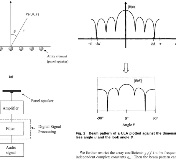
Figure 1 shows a linear speaker array and its signal processing unit. For a uniformly linear array, it is well known that the direc-tional response is the spatial Fourier transform of the array coef-ficients 关2兴. It is then straightforward to obtain a frequency-invariant, omnidirectional array by using inverse Fourier transform. However, the omnidirectionality is generally achieved at the expense of array efficiency. The array coefficients resulting from inverting perfect spectral flatness tend to be an impulse func-tion in the spatial domain, which implies only one element in the array is active and the remaining elements are at rest. Instead of the above naı¨ve approach, a method of optimization was em-ployed in this paper to calculate the array coefficients that attain optimal efficiency with a desired directional response, or spectral flatness in the transformed domain. Due to the highly nonlinear nature of the array optimization problem, this study employs an optimization technique, the genetic algorithm共GA兲, to effectively search the global optimum in a nonlinear space with a large
num-ber of parameters. Typically, there are 2(2N⫹1) parameters, in-cluding the magnitudes and phases, to determine for an array with 2N⫹1 elements. Thus, the search space can be very large for a moderate number of array elements. The GA is well suited for dealing with such optimization problems. Reference关3兴 optimized a linear array and a planar array using GA to produce beam pat-terns with the lowest side-lobe level. Reference关4兴 also proposed a design technique for linear array using optimization methods. As opposed to the optimization-based approaches, Ref.关5兴 suggested an array design method that does not yield optimal, but reasonable results, while the analytical solution guarantee a certain amount of control that is not present when an optimization method is used.
This paper proposes a GA-based technique for finding array coefficients to maximize two cost functions: spectral flatness and array efficiency. Admittedly, the motivation of this research comes to some extent from关5兴, where array efficiency and spectral flat-ness were achieved in an analytical manner with real coefficients. However, the present research differs from 关5兴 in that complex coefficients are employed in the design to provide more degrees of freedom than real-coefficient design during the optimization pro-cess. However, this set of complex coefficients applies to one frequency only. The same procedure must be repeated to gather sufficient frequency samples for designing time domain array fil-ters. The details of the design procedure will be presented in the following sections. In addition to the basic version, a modified design is also proposed to further enhance the efficiency in the low frequency range, where the design effort can be shifted from the ‘‘invisible’’ region to the ‘‘visible’’ region. These two optimal designs are referred in this paper as the omnidirectional array and the modified omnidirectional array.
In order to verify the proposed optimal array designs, experi-ments were carried out in this research. A small 5⫻1 panel speaker array and a large 3⫻3 panel speaker array were con-structed for experimental verification. Signal processing and elec-tronic compensation are carried out by using a multichannel digi-tal signal processor 共DSP兲. Results obtained using the optimal designs will be discussed with reference to an uncompensated array.
Contributed by the Technical Committee on Vibration and Sound for publication in the JOURNAL OFVIBRATION ANDACOUSTICS. Manuscript received August 2002; final revision March 2004. Associate Editor: Richard F. Keltie.
2 Fundamentals of Uniformly Linear Arrays
The array configuration employed in this work is the uniformly linear array共ULA兲 in which array elements are equally spaced in a straight line. Some fundamentals of ULA relevant to the ensuing discussion are given in this section.
2.1 Far-Field Model of a ULA. Consider the ULA with 2N⫹1 elements, as shown in Fig. 1共a兲. The observation point is assumed in the far-field such that rⰇ2Nd, where d is the spacing between two adjacent elements and r is the distance between the observation point and the array center. As a rule of thumb, the far field begins at the distance three times the characteristic dimen-sion of the source关4兴 or, in our case, 2Nd. The sound pressure of this array is given by关5兴
P共 f ,,r兲⫽A共 f ,兲R共 f ,r兲B共 f ,兲 (1) where f is the frequency of the source, is the angle measured from the normal of the array, A( f ,) is the directional response of a single array element, and R( f ,r)⫽r⫺1exp(j2fr/c) represents the spherical spreading. The beam pattern B( f ,) is expressed as
B共 f ,兲⫽
兺
n⫽⫺N N
gn共 f 兲ejn共2 f d sin /c兲 (2)
where gn( f ) is the array coefficient of the nth element and c is
the speed of sound.
We further restrict the array coefficients gn( f ) to be
frequency-independent complex constants gn. Then the beam pattern can be
written as
B共u兲⫽
兺
n⫽⫺N N
gnejnu (3)
where the dimensionless angle u⫽kd sin⫽2fd sin /c; k being the wave number, d being the interelement spacing, f being the frequency, and c being the speed of sound. Inspection of Eq.共3兲 reveals that the beam pattern is essentially the frequency response of a FIR filter with coefficients gn. Thus, the design problem of
an omnidirectional array can be regarded as the design of an all-pass FIR filter.
2.2 Charateristics of a ULA. Analogous to time-domain filters, a ULA is a filter in the spatial domain, where the wave number k is the spatial frequency, the spacing d is the spatial sampling period, and the nondimensional angle u is the digital spatial frequency. Increase of the array aperture will result in the decrease of the beam width and thus improved resolution.
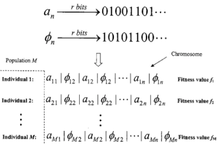
The beam pattern of a typical ULA is shown in Fig. 2. The nondimensional angle u⫽2 f d sin/c is a nonlinear function of the look angle . The beam-broadening effect arises as varies from 0 deg to ⫾90 deg. When the main beam of an array is steered to0, its beam width can be approximated as关2兴
2⌬⬇2 c
共2N⫹1兲d cos0
(4) where⌬ is the angle difference between the look angle 0 and the adjacent null point andc is the source wavelength.
The physical limits of the look angle ⫽⫾90 deg correspond to the dimensionless angle u0⫽⫾kd for specific wave number k and interelement spacing d, which in turn increases with increas-ing frequency f . Note that the parameter u0 is then likely to be greater than above a certain frequency. In this case, grating Fig. 1 A linearly uniform linear array.„a…The schematic of a
panel speaker array,„b…the signal processing unit of the panel speaker array
Fig. 2 Beam pattern of a ULA plotted against the dimension-less angleuand the look angle
lobes will appear within the observation range. To avoid the grat-ing lobes, the spacgrat-ing d is generally chosen accordgrat-ing to
d⭐
2 (5)
where⫽c/ f is the wavelength and c is the speed of sound.
2.3 Omnidirectional Response. As mentioned previously, the goal of this work is to design speaker arrays with omnidirec-tional characteristics. Some considerations with regard to this as-pect are addressed as follows. The dashed line in Fig. 3 shows a typical omnidirectional beam pattern plotted in the u-domain. The smaller the ripples are, the closer the array is to the ideally omni-directional response. Since the parameter u is dimensionless, the omnidirectional response applies to all frequencies.
The array efficiency can be enhanced by a further modification to the directional response design. With reference to Fig. 3, in sufficiently low frequency, it could happen that the effective range at which the look angle falls within the range 关⫺/2,/2兴 cor-responds to a nondimensional critical angle less than 共i.e., u0
⫽kd sin(/2)⫽kd⬍). The regions 关⫺,⫺kd) and (kd, 兴 are physically ‘‘invisible.’’ Therefore, it would be a waste to provide energy in the invisible regions共shadow areas兲 during the design process because in those regions no sound radiation will physi-cally exist. Alternatively, it is more desirable to design a band-pass array pattern共solid line in Fig. 3兲, concentrating within the ‘‘visible’’ region关⫺,兴, such that the overall efficiency can be improved. In Section 3, a phase-compensation scheme will be presented to produce an omnidirectional pattern, while at the same time to prevent the design effort from being wasted in the invis-ible region.
3 Optimization Schemes for Omnidirectional Arrays
In this section, optimization schemes are presented that are aimed at achieving a better compromise between array efficiency and the omnidirectional response for the panel speaker array.
3.1 Preliminary Scheme. Let the autocorrelation function be
R共k兲⫽
兺
n⫽⫺⬁
⬁
gngk*⫺n (6)
where gn is the array gain for the nth element and * denotes
complex conjugate关6兴. The power spectrum is given by
S共u兲⫽兩B共u兲兩2⫽B共u兲B*共u兲. (7)
It can be shown the following relations are valid
gn↔ FT
B共u兲
R共k兲↔
FT
S共u兲, S共u兲⫽B共u兲B*共u兲
C共k兲↔
FT
S2共u兲, S2共u兲⫽S共u兲S*共u兲 where
C共k兲⫽
兺
n⫽⫺⬁
⬁
R共n兲R*共k⫺n兲
and FT denotes the Fourier transform. Thus, by the above Fourier relations
S2共u兲⫽
兺
k⫽⫺⬁
⬁
C共k兲ejku. (8)
It is well known that the power spectrum is the Fourier transform of the autocorrelation function
S共u兲⫽
兺
k⫽⫺⬁ ⬁
R共k兲e⫺ jku. (9) Assume the array consists of 2N⫹1 elements. The first perfor-mance index employed in the optimization procedure is the ‘‘array efficiency’’ ⫽共2N⫹1兲max 兩gR共0兲 n兩 (10) where g⫽兵gn兩⫺N⭐n⭐N,n苸N其, and R共0兲⫽
兺
n⫽⫺N N 兩gn兩2⫽ 1 2冕
⫺ S共u兲du (11)where the Parseval theorem has been invoked. Thus, the array efficiency can be interpreted as the mean-square spectrum normal-ized by max兩gn兩. The array efficiency will be close to unity if all
array elements are quite active. Using Eq.共9兲, we have
1 2
冕
⫺ S共u兲du⫽冕
⫺ 兺
k⫽⫺2N 2N R共k兲ejkudu⫽R共0兲. (12)By the Parseval’s relation,
兺
k⫽⫺2N 2N 兩R共k兲兩2⫽ 1 2冕
⫺ S2共u兲du. (13)Define the ‘‘merit factor’’ as关7兴
Fa⫽ R2共0兲
兺
k⫽0 兩R共k兲兩 2 . (14)The interpretation of the merit factor follows from substituting Eqs.共12兲 and 共13兲 into Eq. 共14兲
Fa⫽
冉
冕
⫺ S共u兲du冊
2 2冕
⫺ 关S2共u兲⫺R2共0兲兴du (15)where the denominator of Facan also be written as the spectral
variance, or the measure of flatness Fig. 3 The full band design and the bandpass design for the
omnidirectional array. Solid line represents bandpass beam pattern, dashed line represents full band beam pattern
vf,
兺
k⫽0兩R共k兲兩 2⫽冕
⫺ 关S2共u兲⫺R2共0兲兴du ⫽冕
⫺ 关S共u兲⫺R共0兲兴2 du. (16)Thus, the merit factor Fa can be interpreted as the ratio of the
square spectrum over the spectral variance. The mean-square spectrum can be related to the efficiency of the array, whereas the spectral variance can be related to the spectral flat-ness. It is then most desirable to have an array with a large merit factor, i.e., high efficiency and small variance. However, there is generally a tradeoff between these two indices, which entails for the need of an optimization procedure to best accomplish this tradeoff.
3.2 Modified Scheme. It is mentioned previously that, in the low frequency when the critical frequency u0⫽2 f0d/c
⬍, energy can be wasted in the invisible region. To avoid this pitfall in the array design, we thus modify Eq.共15兲 to concentrate the effort on only the visible region 关⫺u0,u0兴. The modified merit factor Fbis written as
Fb⫽
冉
冕
⫺u0 u0 S共u兲du冊
2 2u0冕
⫺u0 u0 关S共u兲⫺s兴2du (17) where s⫽ 1 2u0冕
⫺u0 u0 S共u兲du. (18)Equation共18兲 can be expressed as s⫽ 1 2u0
冕
⫺u0 u0兺
k⫽⫺⬁ ⬁关R共k兲ejku兴du.
With some manipulations, above equation can be rewritten as s⫽ 1 2u0k⫽⫺⬁
兺
⬁冋
R共k兲2 sin共ku0兲 k册
. (19) Define Gs⫽ 1 2u0冕
⫺u0 u0 S2共u, f 0兲du. (20)From Eqs.共8兲, 共18兲, and 共19兲, Eq. 共20兲 can be expressed as
Gs⫽ 1 2u0k⫽⫺⬁
兺
⬁冋
C共k兲2 sin共ku0兲 k册
. (21)With some manipulations, the denominator of Fbin Eq.共17兲 can
be written as 2u0
冕
⫺u0 u0 关S共u, f0兲⫺s兴2du⫽4u0 2 Gs⫺4u0 2 s 2 . Equation共17兲 can now be written asFb⫽
冉
冕
⫺u0 u0 S共u, f0兲du冊
2 2u0冕
⫺u0 u0 关S共u, f0兲⫺s兴2du ⫽ s 2 Gs⫺s 2. (22) 4 Genetic AlgorithmThe genetic algorithm共GA兲 is an optimization algorithm based on the theory of biological evolution关8兴. The GA is particularly
useful for solving complex and nonconvex problems in discrete space with a large number of parameters. The main difference between the GA and other search algorithms is that the GA oper-ates on a ‘‘population’’ of strings 共chromosomes兲 instead of a single starting point. Each chromosome is associated with a ‘‘fit-ness’’ value as the performance measure. The GA forms ‘‘genera-tions’’ of solution candidates and attempts to maximize the total fitness of each generation. Owing to the multiple-starting-point nature of the algorithm, the GA is less likely to be trapped in a local optimum than many other optimization methods.
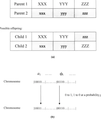
4.1 Design Procedure of the GA. The first step of the GA is to encode the input parameters for the fitness function into binary numbers. As shown in Fig. 4, the array coefficients gn
⫽anejn, n⫽⫺N,⫺N⫹1, . . . ,N⫺1, N, are encoded in an r-bit
discrete space. Then all coefficients are concatenated to form a binary string called a chromosome. The corresponding fitness value is computed.
The flowchart of the array design using GA is shown in Fig. 5. To initialize the GA procedure, M individuals are randomly gen-erated to form the first generation. In a GA cycle, three types of operators are invoked.
Reproduction: Each individual in the current population has a
possibility of being selected to form the next generation according to the fitness. The probability to be selected for the kth chromo-some is pk⫽ fk⫺ fmin
兺
i⫽1 M 共 fi⫺ fmin兲 (23)where fiindicates the fitness function of the ith chromosome and
fminindicates the minimum fitness value in the M chromosomes.
Crossover: With the crossover probability pc, this step copies
data from two parent individuals generated in the previous step to form new child solutions. The method used in this paper is the
doublepoint crossover, where the two points are randomly chosen,
as shown in Fig. 6共a兲. This splits each parent into three segments. The first child solution is formed by randomly copying each seg-ment from either of the parents. The second child solution is formed from the segments not used by the first child. The parents are then replaced by their offsprings.
Mutation: This step is performed on each the chromosome
ac-cording to the mutation probability pmby randomly altering
chro-mosomes, as shown in Fig. 6共b兲. The mutation probability pm
must be chosen appropriately. If pm is too large, the GA will
diverge. Conversely, if pm is too small, the GA will terminate
prematurely.
4.2 Application of the GA to the Array Design Problem
The parameters for the GA in our array design problem are
gn⫽anejn, n⫽⫺N, . . . ,N (24)
where gnis a complex constant and an,nare the magnitude and
phase.
First, M sets of array coefficients an, nare randomly
gener-ated. The ranges of the magnitude anand the phasenare
0⭐an⭐1 and 0⭐n⭐2.
Then, divide the full range into 2rlevels according to the desired
resolutions and round the coefficients to the nearest integer. En-code the coefficients anandninto r-bit binary representations.
Then the binary codes of all 2(2N⫹1) coefficients are concat-enated to form a chromosome. We note in passing in the GA
flowchart of Fig.共5兲, that the initially generated random numbers have to pass a preliminary screening process based on a threshold of flatness vf g defined in Eq. 共16兲 共the inner loop labeled with
‘‘No’’兲. Next, the complete GA cycle involving reproduction, crossover and mutation is applied, under the following constraints, to maximize the merit factor defined in Eq.共14兲. The GA proce-dure will repeat itself共the outer loop labeled with ‘‘No’’兲 until a given target of fitness function, or the merit factor, is met.
4.3 Constraints. In order to ensure uniqueness of solutions, two fundamental constraints must be incorporated into the optimi-zation procedure. The first constraint pertains to the scaling of the array pattern. In order to simplify the formulation, we assume that the gain of the center element is unity.
g0⫽1, and 兩gk兩⭐1, where ⫺N⭐k⭐N, k苸N. (25)
The second constraint pertains to the ‘‘rotation’’ of the array pattern. To avoid nonunique solutions due to rotation, the follow-ing constraint applies
⬔g0⫽⬔g1⫽0. (26)
To further simplify the formulation, the magnitudes of the array coefficients are assumed to be symmetric about the center element.
兩g⫺N兩⫽兩gN兩,兩g⫺N⫹1兩⫽兩gN⫺1兩, . . . ,兩g⫺1兩⫽兩g1兩. (27) Therefore, with these constraints taken into account, the GA procedure is applied to each frequency, resulting in an optimal set of ‘‘complex’’ array coefficients for this frequency. For f⬍c/2d, both schemes can be used, whereas for f⬎c/2d only the prelimi-nary scheme is required. Let gn,1, gn,2, . . . , gn,mbe the complex
array coefficients corresponding to the nth element with respect to the center frequencies f1, f2,, fm. These complex coefficients
gn,1, gn,2, . . . , gn,mserve as the frequency response samples
as-sociated with the filter of the nth array element. In order to obtain an array appropriate for real-time processing of broadband sig-nals, we simply applied the inverse fast Fourier transform共IFFT兲
Fig. 5 Flow chart of the GA procedure
Fig. 6 GA operators„a…crossover;„b…mutation
to calculate the finite impulse response共FIR兲 filter coefficients for each array element. In this final step, circular shift may be applied to ensure the causality of the resulting filters.
5 Verification of GA-based Array Design
5.1 Numerical Simulation. A simulation was carried out for the omnidirectional array, using the preliminary scheme. With reference to the fitness function, or the merit factor Fain Eq.共14兲,
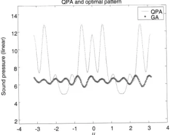
we choose M⫽200, r⫽16, and N⫽6 in the simulation. Hence, 6 magnitude parameters and 11 phase parameters of the array ele-ments are arranged into one chromosome. The probabilities of crossover and mutation are set to be 0.85 and 0.01, separately. After approximately 300 iterations through the outer loop labeled with ‘‘No’’ in Fig. 5共approximately 20 min on a Pentium 3兲, the fitness function of the GA algorithm settles to the maximum value. The learning curve is shown in Fig. 7 and the results found by GA are summarized in Table I. Figure 8 compares the beam pattern兩B(u)兩 obtained by the GA with the beam pattern obtained by the quadratic phase array共QPA兲 关5兴. It can be seen from the result that the GA design that is based on the procedure in Fig. 5 with the merit factor of Eq.共14兲 produced a flatter array pattern than the QPA design.
Next, the modified scheme is investigated. The fitness function, or the merit factor Fbin Eq.共22兲, is used in the GA procedure.
Choose u0⫽1.5 and N⫽2 in the optimization program. Simulated beam pattern using optimal array coefficients is shown in Fig. 9.
Using the modified scheme, we are able to concentrate the beam pattern in the visible region, u⫽⫺1.5⬃1.5. This enhancement of efficiency is obtained for the frequency
f⬍u0c
2d. (28)
For a frequency 1123 Hz satisfying the above relation, we com-pare the beam patterns between the two designs using the prelimi-nary scheme and the modified scheme, respectively. The spacing
d⫽6.7 cm. The results in Fig. 10 show that the array using the
modified scheme gives larger output than the array using the pre-liminary scheme.
5.2 Experimental Investigation. A small 5⫻1 linear panel speaker array and a large 3⫻3 panel speaker matrix are con-structed for experimental verification. The dimensions of the small panels are 7 cm⫻6.7 cm and the dimensions of the large panels are 30 cm⫻30 cm. The spacing d is 6.7 cm in the 5⫻1 array and 30 cm in the 3⫻3 matrix. The resulting designs are implemented on a digital signal processor 共DSP兲 platform. All measurements were conducted inside a 3 m⫻3 m⫻4 m anechoic chamber.
Fig. 7 Learning curve of the fitness function in the GA-based 13Ã1 array„preliminary scheme…
Table 1 The array coefficients for the 13Ã1 optimal array„ pre-liminary scheme…and the QPA array
Element index Optimal array QPA (z⫽18)
⫺6 0.13 exp(j0.72) 0.74 ⫺5 0.52 exp(⫺j2.64) ⫺0.78 ⫺4 0.64 exp(⫺j0.29) 0.96 ⫺3 0.53 exp(j1.80) ⫺1.00 ⫺2 1.00 exp(⫺j1.81) 0.45 ⫺1 0.87 exp(j0.78) 0.67 0 1 ⫺0.86 1 0.87 ⫺0.67 2 1.00 exp(j1.81) 0.45 3 0.53 exp(j1.34) 1.00 4 0.64 exp(j0.29) 0.96 5 0.52 exp(⫺j0.50) 0.78 6 0.13 exp(⫺j0.72) 0.74 Efficiency 0.63 0.63 Flatness 0.12 5.95
Fig. 8 Comparison of beam patterns between the QPA and the GA„preliminary scheme…at the same efficiency requirement
Fig. 9 Beam pattern obtained using the modified scheme, plotted against the dimensionless angle
The first experiment pertains to the verification of the array design using the preliminary scheme of the GA procedure. Figure 11 shows the measured beam pattern of the 5⫻1 panel speaker array at the frequency 3 kHz. Figure 12 shows the measured beam pattern of the 3⫻3 panel speaker matrix at the frequency 1514 Hz. The results of these two figures indicated that the compen-sated array resulting from the modified GA design exhibits omni-directional characteristics within the angles approximately from ⫺60 deg to 60 deg.
The second experiment pertains to the verification of the array design using the modified scheme of the GA procedure. Figure 13 shows the measured beam pattern of the 5⫻1 panel speaker array at the frequency 1134 Hz. Figure 14 shows the measured beam pattern of the 3⫻3 panel speaker matrix at the frequency 879 Hz. From the experimental results, it is observed that the modified scheme of GA procedure indeed produced a design with a higher output level than the preliminary scheme.
6 Conclusions
It has been illustrated in this work that an omnidirectional ra-diation pattern of panel speaker array can be achieved by using the GA-based optimization method. Both numerical and experi-mental investigations are carried out to justify the proposed tech-niques. A preliminary scheme and a modified scheme were devel-oped to maximize the array efficiency under desired spectral flatness requirement. The GA proved to be an effective search technique for the current array design problem. In particular, the modified scheme is able to enhance the efficiency in frequency
f⬍c/2d . The proposed GA procedure generally yields a
satisfac-tory design with a short computational time. For the broadband case, both schemes can be combined to deal with different fre-quency ranges.
The resulting optimal designs are implemented on a DSP plat-form and are experimentally verified by using a small 5⫻1 panel speaker array and a large 3⫻3 panel speaker array. The
experi-Fig. 10 Comparison of beam patterns between the two de-signs using the preliminary scheme and the modified scheme, respectively. The frequency is 1123 Hz, and the spacing
dÄ6.7 cm
Fig. 11 Measured beam pattern of the 5Ã1 panel speaker ar-ray in the frequency 3 kHz. The arar-ray is designed using the preliminary scheme of the GA procedure„dashed line: uncom-pensated; solid line: compensated using the GA design…
Fig. 12 Measured beam pattern of the 3Ã3 panel speaker ma-trix in the frequency 1514 Hz. The array is designed using the preliminary scheme of the GA procedure„dashed line: uncom-pensated; solid line: compensated using the GA design…
Fig. 13 Measured beam patterns of the 5Ã1 panel speaker array in the frequency 1123 Hz „dashed line: preliminary scheme; solid line: modified scheme…
mental results indicate that the proposed GA techniques are able to produce an array design with an omnidirectional beam pattern. Between the two designs, the modified scheme yields more output by shifting the effort from the invisible region to the visible.
Although the ultimate goal of this work was to develop the large array, we were unable to verify its far-field behavior due to
the limitation of current measuring environment. Much work is continuing in improving the implementation as well as measure-ment of the large array for future research.
Acknowledgments
Special thanks are due to the illuminating discussions with NXT, New Transducers Limited, UK. The work was supported by the National Science Council in Taiwan, under the Project No. NSC 89AFA06000714.
References
关1兴 Bai, M. R., and Huang, T., 2001, ‘‘Development of Panel Loudspeaker
Sys-tem: Design, Evaluation and Enhancement,’’ J. Acoust. Soc. Am., 109, pp. 2751–2761.
关2兴 Johnson, D. F., and Dudgeon, D. F., 1993, Array Signal Processing Concepts
and Techniques Prentice Hall, Englewood Cliffs, NJ.
关3兴 Haupt, R. L., 1994, ‘‘Thinned Arrays Using Genetic Algorithms,’’ IEEE Trans.
Antennas Propag., 42, pp. 993–999.
关4兴 Smith, D. L., 1997, ‘‘Discrete-Element Line Arrays: Their Modeling and
Op-timization,’’ J. Audio Eng. Soc., 45, pp. 949–964.
关5兴 Aarts, R. M., and Janssen, A. J. E. M., 2000, ‘‘On Analytic Design of
Loud-speaker Arrays with Uniform Radiation Characteristics,’’ J. Acoust. Soc. Am., 107, pp. 287–292.
关6兴 Beenker, G. F. M., Claasen, T. A. C. M., and Hermens, P. W. C., 1985, ‘‘Binary
Sequences With a Maximally Flat Amplitude Spectrum,’’ Philips J. Res., 40, pp. 289–304.
关7兴 Golay, M. J. E., 1982, ‘‘The Merit Factor of Long, Low Autocorrelation Binary
Sequences,’’ IEEE Trans. Inf. Theory, 28, pp. 543.
关8兴 Belew, R. K., and Vose, M. D., 1997, Foundations of Genetic Algorithms,
Morgan Kaufmann Publishers, New York.
关9兴 Augspurger, G. L., 1990, ‘‘Near-Field and Far-Field Performance of Large
Woofer Arrays,’’ J. Audio Eng. Soc., 38, pp. 231–236.
关10兴 Meyer, D. G., 1984, ‘‘Digital Control of Loudspeaker Array Directivity,’’ J.
Audio Eng. Soc., 32, pp. 747–754.
关11兴 Oppenheim, A. V., and Schafer, R. W., 1989, Discrete-Time Signal Processing,
Prentice Hall, Englewood Cliffs, NJ. Fig. 14 Measured beam patterns of the 3Ã3 panel speaker
matrix in the frequency 879 Hz „dashed line: preliminary scheme; solid line: modified scheme…