國
立
交
通
大
學
資訊學院 資訊學程
碩
士
論
文
PIAFS 在 GPRS/PHS 雙模手機上的應用
PIAFS Implementation in the GPRS/PHS Dual Mode Handset
研 究 生:周欽弘
指導教授:林一平 教授
PIAFS 在 GPRS/PHS 雙模手機上的應用
PIAFS Implementation in the GPRS/PHS Dual Mode Handset
研 究 生:周欽弘
指導教授:林一平
Student:Chin-Hung Chou
Advisor:Yi-Bing Lin
國 立 交 通 大 學
資訊學院 資訊學程
碩 士 論 文
A ThesisSubmitted to College of Computer Science National Chiao Tung University in partial Fulfillment of the Requirements
for the Degree of Master of Science
in
Computer Science July 2008
Hsinchu, Taiwan, Republic of China
PIAFS 在 GPRS/PHS 雙模手機上的應用
學生:周欽弘
指導教授:林一平 教授
國 立 交 通 大 學
資 訊 學 院 資 訊 學 程 碩 士 班
中文摘要
Personal Handyphone System Internet Access Forum Standard (PIAFS) 為
Personal Handyphone System (PHS) 數據傳輸的標準協定,它採用 32-kbps
或
64-kbps 電路模式的非限制數字承載。在本論文中,我們定義了 General
Packet Radio Service (GPRS)/PHS 雙模手機的架構,以及在這兩個系統間
PIAFS 訊息與資料的傳輸。我們將軟體 PIAFS 模組實作在 PHS 模組裡,
Internet 應用程式則是實作在 GPRS 模組上。GPRS/PHS 雙模手機能夠根據
使用者的需求,使用
GPRS 或 PHS 的無線傳輸服務來做 Internet 應用。此
上網應用包含了
Wireless Application Protocol (WAP) 瀏覽器,以及將雙模
手機當作數據機,提供電腦使用網路服務。
II
PIAFS Implementation in the GPRS/PHS Dual Mode Handset
Student:Chin-Hung Chou
Advisor:Dr. Yi-Bing Lin
Degree Program of Computer Science
National Chiao Tung University
ABSTRACT
Personal Handyphone System Internet Access Forum Standard (PIAFS) is the specification for Personal Handyphone System (PHS) data communications. PIAFS data transmission
procedure supports 32-kbps or 64-kbps unrestricted PHS digital bearers. In this thesis, we define the General Packet Radio Service (GPRS)/PHS dual mode handset architecture and
design the mechanism of the PIAFS message and data transmission between the two systems in the dual mode handset. The software PIAFS module is implemented in the slave (PHS) part,
and the Internet applications is in the master (GPRS) part. We develop a GPRS/PHS dual mode handset to support Wireless Application Protocol (WAP) browser on the GPRS
platform, and to access the WAP browser through GPRS or PHS data bearer networks at user’s choice. A user may surf the Internet by WAP browser on the dual mode handset or by a
Acknowledgment
Most of all, I would like to thank my advisor, Prof. Yi-Bing Lin. Without his supervision and
perspicacious advices, there is no way I can complete this thesis and learn so much out of it. I am also very grateful to my colleagues for their partnership and valuable comments about the
thesis. During the two-year study at school, I feel I owe many thanks to my classmates for all their support. And of course, I would never forget about all my dear friends for their
consideration. Last but not least, my thanks to my family for their firmly support over these years cannot be expressed by words.
IV
Contents
中文摘要 ... I ABSTRACT ... II Acknowledgment ... III Contents ... IV List of Tables ... V List of Figures ... VI1. Introduction ... - 1 -
2. GPRS/PHS Dual Mode Handset Architecture ... - 9 -
3. PIAFS Message Flow ... - 15 -
3.1. PIAFS Connection ... - 15 -
3.2. PIAFS Disconnection Request ... - 18 -
3.3. PIAFS Disconnection Indication ... - 20 -
4. Performance Evaluation ... - 22 -
5. Conclusion ... - 26 -
List of Tables
Table 1. The AT Commands of the Master Part ... - 12 -
Table 2. The AT+PIND Indication Format ... - 13 -
Table 3. The Downloading Transmission Rate (bps) for the Integrated Type ... - 24 -
VI
List of Figures
Figure 1. Network Configurations for PHS Service Domains ... - 2 -
Figure 2. PHS Data Terminal Types ... - 5 -
Figure 3. PIAFS Protocol Stacks ... - 7 -
Figure 4. Dual Mode Handset Architecture ... - 9 -
Figure 5. WAP and Modem Protocol Stacks over PIAFS ... - 11 -
Figure 6. Data Flow between the Master Part and the Slave Part ... - 14 -
Figure 7. The Message Flow of the Connection Request ... - 15 -
Figure 8. The Message Flow of the Disconnection Request ... - 18 -
Figure 9. The Message Flow of the Disconnection Indication ... - 20 -
Figure 10. The Transmission Rate Test Environment ... - 22 -
1. Introduction
The Personal Handyphone System (PHS) service was commercially launched in Japan in
1995. Today, more than 10 countries and regions have provisioned commercial PHS services. PHS standardization activities were initiated by the Association of Radio Industries and
Businesses (ARIB) and Telecommunication Technology Committee (TTC) of Japan. The PHS air interface was standardized in 1993 by ARIB, and the details are described in RCR
STD-28 [1].
PHS uses Time Division Multiple Access / Time Division Duplex (TDMA/TDD) for radio channel access. PHS voice codec is 32-kbps Adaptive Differential Pulse Code Modulation
(ADPCM) based on the ITU-T Recommendation G.726 [2]. The ADPCM compresses speech data without degrading speech quality. The PHS system is used for data transmission as well
as speech communications. Modern PHS phone operators also support many value-added services such as high speed wireless data (64-kbps and higher), Internet connection, WWW
access, e-mailing, text messaging, and color image transfer.
The PHS Common Air Interface (CAI) is standardized in RCR STD-28 [1], and its User-Network and Network-Network Interfaces (UNI and NNI) are defined in ITU-T Q-series
standards [3]. The PHS Internet Access Forum (PIAF) was organized in July 1995 in order to promote PHS multimedia communications. The promotional works were inherited from the
PIAF to Mobile Internet Access Forum (MITF) and then to the ARIB. The PIAF Standard (PIAFS) V1.0 was finalized in 1996, which is a data transmission procedure that supports
32-kbps unrestricted PHS digital bearer [4]. The 32-kbps unrestricted data transmission service was commercialized in Japan on April 1, 1997. In November 1997, the ARIB
- 2 -
64-kbps digital bearer. Accordingly, PIAFS V2.0 was enhanced to support 64-kbps
unrestricted PHS digital bearer in October 1998. The current specification number is ARIB STD-T76 [4]. PS CS PSTN WSU WCS WAC WPS TE CS CS Digital PABX PS PS (4) Home Digital Cordless Telephone (3) Wireless PABX (5) Walkie-talkie (1) Public Digital Cordless Telephone (2) WLL / FWA CS: Cell Station
PABX: Private Automatic Branch eXchange PS: Personal Station
PSC: PHS Switching Center
PSTN: Public Switched Telephone Network
TE: Terminal Equipment
WAC: WLL/FWA Access Controller WCS: WLL/FWA Cell Station
WLL/FWA: Wireless Local Loop/Fixed Wireless Access WPS: WLL/FWA Personal Station
WSU: WLL/FWA Subscriber Unit PSC PS PS PHS Adaptor PS CS
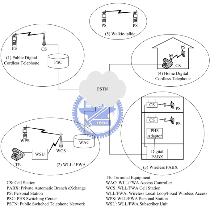
Figure 1. Network Configurations for PHS Service Domains
Figure 1 shows five PHS network configurations in public and private telecommunications
service domains [5]. In this figure, Public Switched Telephone Network (PSTN) is a circuit-switched telephone network system designed to allow transmission of voice and data
over ordinary telephone copper wires. The PHS service domains connected to PSTN are
described as follow:
z Public Digital Cordless Telephone (Figure 1 (1)) enables public wide area
communications service with mobility. In this configuration the PHS Switching Center (PSC) is a digital switching system installed with PHS service software. The PSC
connects the calls from the Personal Stations (PSs) to the PSTN through the Cell Station (CS). The CS interfaces with the PSC through a modified ISDN protocol that supports
PHS-specific functions such as location registration, authentication, and handover. A PS communicates with the CS via the PHS air interface.
z Wireless Local Loop/Fixed Wireless Access (WLL/FWA) system (Figure 1 (2))
substitutes the existing telephone twisted pair to provide subscribers with telephone
services. The WLL/FWA Access Controller (WAC) has a Local Exchange (LE) interface and a WLL/FWA Cell Station (WCS) interface. The WAC controls call connection, and
performs location registration and authentication. The WCS communicates with WLL/FWA Subscriber Unit (WSU) and/or the WLL/FWA Personal Station (WPS) using
the PHS air interface. The WCS is typically installed on the top of a pole or the roof of a building. The number of subscribers per cell can be increased by using multiple
transceiver facilities of the WCS. The WSU converts signals between the Terminal Equipment (TE) and the WCS. In order to serve as a subscriber line to the telephone, a
WSU includes features such as DP (Dial Pulse)/DTMF (Dual Tone Multi-Frequency signaling) transmission/reception and the generation of the howler/ringer. The WPS is a
mobile subscriber terminal similar to the public PHS PS.
z Wireless Private Automatic Branch eXchange (PABX) system (Figure 1 (3)) provides
office mobility and greater flexibility in the office environments. The digital wireless PABX system consists of PSs, CSs, and a digital PABX. The air interface between PSs
- 4 -
such as location registration and authentication are installed in the PABX. The CSs can
be directly connected to the PABX through the interface cards. Alternatively, the CSs and the PSs can be controlled by the PHS adapter that treats each PS as an ordinary
extension line for the PABX.
z Home Digital Cordless Telephone (Figure 1 (4)) consists of PSs and a CS that provides
cordless base unit function. PHS terminal mobility is an important concept of PHS. This concept enables the users to move seamlessly between public and private PHS services.
In the public environment, the PS can be a mobile terminal of the public PHS service. At home, the same PS can be an extension of a home digital cordless telephone. When the
PS is within the range of both the public and the private systems, the PS can be paged from both systems.
z Transceiver (walkie-talkie) Mode (Figure 1 (5)) enables a PS to communicate directly
with another PS without the involvement of the CS.
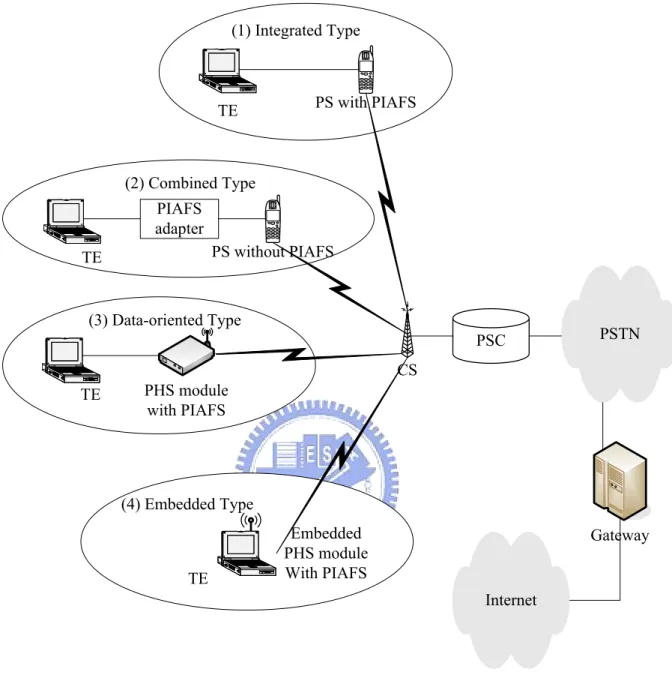
Based on the PIAFS, Figure 2 shows several types of PHS data terminals for the public digital
cordless phone service domain. The Gateway supports interworking between the PSTN and the Internet, and converts the data packets between the PIAFS and the standard TCP/IP [6]
[7].
z In the integrated type (Figure 2 (1)), the telephone and the PIAFS functions are
physically merged. The handset can also be connected to a TE to serve as a wireless modem.
z In the combined type (Figure 2 (2)), a PS without PIAFS is connected to a TE through a
PIAFS adapter via, e.g., a cable with Universal Serial Bus (USB) interface.
z In the data-oriented type (Figure 2 (3)), a TE connects a built-in PHS module with
PIAFS in a PC Card, a Compact Flash (CF) card, or a Secure Digital (SD) card. z In the embedded type (Figure 2 (4)), the PHS module with PIAFS is built in a TE.
PS without PIAFS CS PIAFS adapter PSTN PSC PS with PIAFS (1) Integrated Type (2) Combined Type (3) Data-oriented Type (4) Embedded Type Embedded PHS module With PIAFS PHS module with PIAFS Internet Gateway TE TE TE TE
Figure 2. PHS Data Terminal Types
Current PIAFS version supports 64-kbps data communications for PHS, which uses multiple 32-kbps channels simultaneously to provide high transmission speed. A standard PHS cell
station supports 4 channels where 3 channels are used for voice and packet data, and the fourth channel is pre-assigned as the control channel. The packet data transmission service
can also utilize the control channel when the control channel’s time slots are not occupied. In this way the radio frequency efficiency can be improved.
- 6 -
PIAFS uses either PHS’s 32 or 64-kbps unlimited digital bearer and provides transmission control procedures (comparable to OSI reference model layer 2) for high quality data
transmission. Data compression can be optionally selected when the parameters are set at the beginning of a communication session.
The PIAFS specifies inband negotiation and Automatic Repeat reQuest (ARQ) transmission
control. Inband negotiation is the process of choosing one data-link protocol out of multiple data-link protocols through the occurrence of terminal negotiations before data-link
establishment. ARQ transmission supports error control in layer 2 in the PHS communication phase. It requests only the error frames to be resent to improve the data transmission rate.
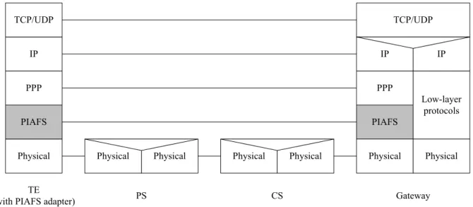
Figure 3 shows the PIAFS protocol stacks [7]. Figure 3 (1) is the integrated type data terminal
PIAFS Physical PPP IP CS TE
(with PIAFS adapter) Physical TCP/UDP Physical PPP IP TCP/UDP Physical Physical Low-layer protocols Physical IP Gateway
(2) PIAFS protocol stack of combined type data terminal PS
PIAFS
Physical
Figure 3. PIAFS Protocol Stacks
Global System for Mobile Communications (GSM) is a digital wireless network stand designed by standardization committees from major European telecommunication operators
and manufacturers. The GSM standard provides a common set of compatible services and capabilities to all mobile users across Europe and several million customers worldwide.
General Packet Radio Service (GPRS) reuses the existing GSM infrastructure to provide end-to-end packet-switched services for bursty data applications such as e-mail and WWW.
GPRS also provides a smooth path to evolve from GSM to the third-generation mobile network [8].
In this thesis, we investigate the development of a GPRS/PHS dual mode handset which can
process both radio access systems. Such dual mode handset will allow a user to enjoy the advantages of both PHS and GPRS networks. While PHS provides high-quality speech and
high-speed data communication with low mobility, GPRS supports larger radio coverage and enhanced mobility.
- 8 -
This thesis describes how to develop a GPRS/PHS dual mode handset architecture to support
Internet applications such as Wireless Application Protocol (WAP) browser or e-mail on the GPRS platform, and to access the applications through GPRS or PHS bearer networks at a
user’s choice. Users may switch the data service between the two systems depending on factors such as the cost, the data speed, or the signal strength. We choose the integrated type
PHS data terminal (see Figure 2 (1)) to implement PIAFS. In this approach, a user may surf the Internet by WAP browser on the phone and by a computer via using the dual mode
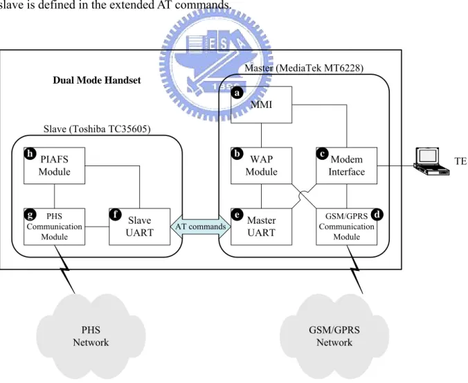
2. GPRS/PHS Dual Mode Handset Architecture
In a typical GPRS/PHS dual mode handset, the GPRS is the master part and the PHS is the
slave part. In our implementation, the GPRS part is implemented by using MediaTek MT6228, which includes the WAP and the modem modules. The PHS part is implemented by using
Toshiba TC35605, which includes Toshiba PIAFS605 as the PIAFS Module. Figure 4 shows the architecture of our dual mode handset. The master part (GPRS) uses basic AT commands
to communicate with the slave part (PHS) via Universal Asynchronous Receiver/Transmitter (UART; see Figure 4 (e) and (f)). In the UART interface, we have defined the extension
commands for the dual mode handset such as network registration, network signal feedback, and hardware control commands. The PIAFS data transmission between the master and the
slave is defined in the extended AT commands.
PHS Communication Module Master UART Slave UART
Dual Mode Handset
AT commands Modem Interface WAP Module TE GSM/GPRS Communication Module Slave (Toshiba TC35605) Master (MediaTek MT6228) GSM/GPRS Network PHS Network MMI PIAFS Module a b c d e f h g
- 10 -
z In the master part, the Man Machine Interface (MMI; see Figure 4 (a)) includes the
input/output devices and software such as keypad, LCD screen, ringing tone, and user
interface software. It allows a user’s request to surf Internet on the GPRS or the PHS service domain, and sets the data path flow of the WAP Module (Figure 4 (b)) and the
Modem Interface (Figure 4 (c)). The WAP Module includes the WAP protocol stack, the lower interfaces to the bear networks (GPRS and PHS), and the upper interface to the
MMI. The Modem Interface can be Bluetooth and/or USB that connect to TE when the GPRS/PHS handset serves as a wireless modem. The GSM/GPRS Communication
Module (Figure 4 (d)) controls the GSM/GPRS data call request, the data flow paths, and the protocol stack for communication with GSM/GPRS network.
z In the slave part, the PHS Communication Module (Figure 4 (g)) controls the PHS data
call request, the data flow paths, and the protocol stack for communication with the PHS
network. The PIAFS Module (Figure 4 (h)) is responsible for the PIAFS data packet transmission with PHS network via the PHS Communication Module.
z UART: The WAP and the Modem modules interact with the PHS part through the Master
UART and the Slave UART (see path [(c) , (b)] ↔ (e) ↔ (f) ↔ [(g) , (h)] in Figure 4).
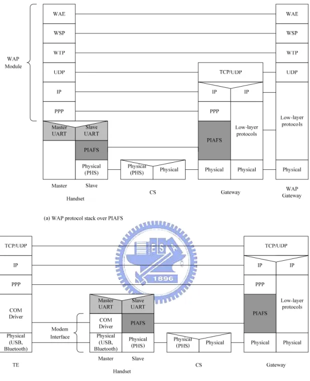
As a layer 2 protocol in the OSI reference model [4], the PIAFS supports Point-to-Point
Protocol (PPP) [9]. Figure 5 illustrates the PIAFS layer and others layers implemented in our dual mode handset. Figure 5 (a) shows the WAP protocol stack based on PIAFS. Figure 5 (b)
shows the modem protocol based on PIAFS. In both cases, UART is used to bridge the master and the slave parts of the handset.
Figure 5. WAP and Modem Protocol Stacks over PIAFS
In this thesis, we develop several extended AT commands between the master part and the slave part. Table 1 shows the format of the AT commands sent from the master part to the slave
part. The details are described as follows.
- 12 -
the called telephone numbers. If the phone number field is followed by a semicolon, then
it represents a data connection. Otherwise it represents a voice connection. z The ATH command terminates a connection.
z The ATA command answers an incoming call.
z The AT+CFUN command sets slave part functionality. The parameter <state> can be,
e.g., power on/off or network registration.
z The AT+PC command sends a data packet to the slave part. The parameter <size> is the
length of the binary data packet in bytes. The master part transmits the desired packet to the slave part after this command is sent.
Table 1. The AT Commands of the Master Part ATD<number>[;] <number>: Called telephone numbers
[;]: Exists if it is a data call
ATH No parameters
ATA No parameters
AT+CFUN:<state> <state>: Power on/off or network registration request
AT+PC:<size> <size>: The size of the user data packet in bytes following this AT command
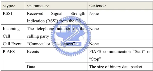
When the slave part receives an AT command from the master part, it executes the instruction, and then returns an “indication” to the master part. The format of an indication sent from the
slave part to the master part is the form AT+PIND:<type>,<parameter>,<extend> (see Table 2). Several extended command types are described below:
z “RSSI” indicates the radio signal strength from the CS. The <parameter> is the Received Signal Strength Indication (RSSI).
the caller does not hide the telephone number, the <parameter> shows the number.
z “Call Event” indicates a call event from the PHS service network. It can be “connect” or
“disconnect”.
z “PIAFS” indicates the PIAFS status events and data transmission. The <parameter>
specifies an event or data transmission. The parameter <extend> shows an event such as
PIAFS communication “start” or “stop”, or the size of the binary data packet. The slave part sends the packet to the master part after this indication is sent.
Table 2. The AT+PIND Indication Format
<type> <parameter> <extend>
RSSI Received Signal Strength
Indication (RSSI) from the CS
None
Incoming Call
The telephone number of the calling party
None
Call Event “Connect” or “Disconnect” None
PIAFS Events PIAFS communication “Start” or
“Stop”
Data The size of binary data packet
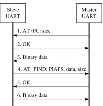
Figure 6 shows how binary data packets is delivered through the AT commands. In this figure, the solid lines represent commands and the dash lines represent binary data delivery. The
Master UART sends the packet size to the Slave UART before sending the desired data packet (see message (1), (2), and (3) in Figure 6). Similarly, the Slave UART indicates the packet
- 14 - Slave UART Master UART 1. AT+PC: size 2. OK 3. Binary data 5. OK
4. AT+PIND: PIAFS, data, size
6. Binary data
3. PIAFS Message Flow
In this chapter, we design the message flows for several PIAFS functions between the
CS/Gateway and the TE. The Gateway supports the PIAFS protocol and interworking between the PSTN and the Internet (see Figure 2). Same message flows can be applied to the
interaction between the CS/Gateway and the MMI of the dual mode handset.
3.1. PIAFS Connection
Slave UART
Master UART
11. AT+PIND: PIAFS, Event, Start 12. Data Connected PIAFS Module PHS Commnication Module
2. Data Connection Request
4. Data Connection Request
13. Connected 10. PIAFS Start Indication
3. ATD <number>; CS
7. PIAFS Start Request
1. Connection Request
6. Call Connected
8. AT+PIND: Call Event, Connect
TE Modem Interface MMI WAP Module Gateway
5. Data Call Connection
9. PIAFS Link Establishment
PIAFS Data Session
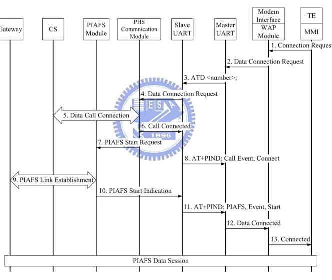
Figure 7. The Message Flow of the Connection Request
Figure 7 illustrates the message flow of the connection request from the TE when the handset served as a wireless modem. Same request can be issued from the MMI for the WAP browser
- 16 -
Step 1. To initiate a data connection, the TE sends the Connection Request message with
the called telephone number to the Modem Interface of the handset.
Step 2. If the preferred network is set to PHS, the Modem Interface in the wireless modem
application sends the Data Connection Request message to the Master UART with the telephone number.
Step 3. The Master UART sends the ATD<number>; message to the Slave UART to
request the data connection. The parameter <number> indicates the telephone
number. The parameter “;” indicates the data call request.
Step 4. The Slave UART sends the Data Connection Request message to the PHS
Communication Module.
Step 5. Several messages are exchanged at this step. Specifically, the PHS Communication
Module sends the data call connection request to the CS, and starts the call connection procedure following the RCR STD-28 protocol [1]. After the connection
is successful, the PHS radio bearer is established.
Step 6. If the PHS network is available, the PHS Communication Module sends the Call Connected message to the Slave UART.
Step 7. At this point, the PHS radio bearer is established. Then the handset proceeds to
establish the PIAFS connection with the Gateway. The PHS Communication Module sends the PIAFS Start Request message to the PIAFS Module to start the PIAFS
link.
Step 8. The Slave UART sends the AT+PIND: CALL, Event, Connect message to the
Master UART indicating the call connection.
Step 9. Several messages are exchanged at this step. Specifically, the PIAFS Module sends
the data link establish request to the Gateway, and starts the data link establishment procedure following the RCR STD-76 protocol [4]. After the data link is successfully
Step 10. After the PIAFS data communication establishment, the PIAFS Module sends the PIAFS Start Indication message to the Slave UART.
Step 11. The Slave UART sends the AT+PIND: PIAFS, Event, Start message to the Master
UART indicating the PIAFS connection.
Step 12. After the Master UART received the AT+PIND at step 8 and step 11, it sends the Data Connected message to the Modem Interface in the wireless modem
application.
Step 13. The Modem Interface sends the Connected message to the TE in the wireless
- 18 -
3.2. PIAFS Disconnection Request
3. ATH
8. AT+PIND: PIAFS, Event, Stop
11. Data Disconnected 2. Data Disconnetion Request
12. Disconnected 4. PIAFS Stop Request
6.1. PIAFS Stop Indication 6.2. PIAFS Stop Indication
9. Call Disconnected
10. AT+PIND: Call Event, Disconnect 5. PIAFS Link Release
7. Data Call Disconnection
PIAFS Data Session
1. Disconnection Request Slave UART Master UART PIAFS Module PHS Commnication Module CS TE Modem Interface MMI WAP Module Gateway
Figure 8. The Message Flow of the Disconnection Request
A PIAFS session can be disconnected through the TE’s, the handset’s MMI, or the Gateway’s disconnection indication. Figure 8 shows the message flow of the disconnection request from
the TE. Same request can be issued from the MMI of the WAP browser on the handset.
Step 1. The TE sends the Disconnection Request message to the Modem Interface. Step 2. If the data session is connected to the PHS service network, the Modem Interface
sends the Data Disconnection Request message to the Master UART.
Step 3. The Mater UART sends the ATH message to the Slave UART to request the call
disconnection.
Step 5. Several messages are exchanged at this step. Specifically, the PIAFS Module sends
the data link release request to the Gateway, and starts the data link release procedure following the RCR STD-76 protocol [4], and the PIAFS communication is
disconnected.
Step 6. After PIAFS disconnection, the handset proceeds to release the radio bearer with the
CS. The PIAFS Module sends PIAFS Stop Indication message to the PHS Communication Module (Step 6.1) and then to the Slave UART (Step 6.2).
Step 7. Several messages are exchanged at this step. Specifically, the PHS Communication
Module sends the data call disconnection request to the CS, and starts the disconnect
procedure following the RCR STD-28 protocol [1], and the PHS radio bearer is released.
Step 8. The Slave UART sends the AT+PIND: PIAFS, Event, Stop to the Master UART
message indicating the PIAFS disconnection.
Step 9. The PHS Communication Module sends the Call Disconnected message to the
Slave UART.
Step 10. The Slave UART sends AT+PIND: Call, Event, Disconnect message to the
Master UART indicating the call disconnection.
Step 11. After the Master UART received the AT+PIND at step 8 and step 10, it sends the Data Disconnected message to the Modem Interface.
- 20 -
3.3. PIAFS Disconnection Indication
4. AT+PIND: PIAFS, Event, Stop
7. Data Disconnected
8. Disconnected 2.1. PIAFS Stop Indication
5. Call Disconnected
6. AT+PIND: Call Event, Disconnect PIAFS Data Session
1. PIAFS Link Release
3. Data Call Disconnection
Slave UART Master UART PIAFS Module PHS Commnication Module CS TE Modem Interface MMI WAP Module Gateway
2.2. PIAFS Stop Indication
Figure 9. The Message Flow of the Disconnection Indication
Figure 9 shows the message flow of the disconnection indication from the Gateway.
Step 1. To release the PIAFS link, the Gateway sends the data link release request to the
PIAFS Module, and starts the data link release procedure following the RCR STD-76
protocol [4], and PIAFS communication is terminated.
Step 2. The PIAFS Module sends the PIAFS Stop Indication message to the PHS
Communication Module (Step 2.1) and then to the Slave UART (Step 2.2).
Step 3. At this point, the PIAFS link is released. The CS proceeds to release the radio bearer
with the handset. The CS sends the data call disconnection request to the PHS Communication Module, and starts the disconnect procedure following the RCR
STD-28 protocol [1], and the PHS radio bearer is released.
Step 4. The Slave UART sends the AT+PIND: PIAFS, Event, Stop message to the Master
Step 5. The PHS Communication Module sends the Call Disconnected message to the
Slave UART.
Step 6. The Slave UART sends AT+PIND: Call, Event, Disconnect message to the
Master UART indicating the call disconnection.
Step 7. After the Master UART received the AT+PIND at step 4 and step 6, it sends the Data Disconnected message to the Modem Interface.
- 22 -
4. Performance Evaluation
The FITEL’s PHS service network and the HINET’s Internet service are chosen for the PIAFS
test. The basic functions such as connect, disconnect, web surfing, and data download, were tested on the WAP browser of the handset. For the transmission rate test, the dual mode
handset was connected to a laptop computer to serve as a wireless modem.
Figure 10 shows the transmission rate test environment. In each test run, 1 MB file in the HINET ftp server (ftp.adsl.hinet.net) is transmitted at 32-kbps and 64-kbps respectively.
Every test run is repeated for 10 times in a period. There are 3 test periods in a day, including 9am-11am, 3pm-5pm, and 9pm-11pm. The experiments are conducted for 3 days. The
transmission rate is investigated in two PIAFS terminal models: the dual mode handset including software PIAFS module (integrated type; see Figure 10(1)), and a PS connected
with an external hardware PIAFS cable (combined type; see Figure 10(2)). As compared with the combined type, the software PIAFS module may decrease the transmission rate of the
integrated type. PS PIAFS adapter FITEL PHS Network Dual Mode Handset
With PIAFS (1) Integrated Type (2) Combined Type Internet Gateway HINET FTP Server TE TE
In the tests, the PIAFS uses two CS channels in 64-kbps digital bearer, and one channel in
32-kbps digital bearer. The CS may changes the assigned channel numbers between one and two depending on the PHS network situation, which affects the data transmission rate. The
theoretical maximum throughput by using 32-kbps unrestricted digital bearer is 29.2 kbps, and is 58.4 kbps for 64-kbps unrestricted digital bearer [5]. Table 3 shows test result of the
downloading rate of the integrated type. Table 4 shows test result of the downloading rate of the combined type. Figure 11 shows the comparison of the transmission rate of these 2 types.
We have the following observations:
z In the 32-kbps downloading test for the integrated type, the average transmission rate is
27.871 kbps with the standard deviation 1.245 kbps. In the 64-kbps downloading test, the average transmission rate is 46.292 kbps with the standard deviation 1.686 kbps.
z In the 32-kbps downloading test for the combined type, the average transmission rate is
27.285 kbps with the standard deviation 1.069 kbps. In the 64-kbps downloading test, the
average transmission rate is 55.363 kbps with the standard deviation 2.223 kbps.
For both the integrated type and the combined type, the 32-kbps downloadings approximate the theoretical transmission rate. In the 32-kbps transmission rate test, the integrated type has
better performance than the combined type. This is because the combined type has an extra hardware that causes the data packet transmission delay. In the 64-kbps transmission rate test,
the integrated type has worse performance than the combined type because of the software PIAFS model implementation. For both types, the standard deviations of the transmission rate
are similar, and the transmission stabilities are the same.
The degraded performance of the 64-kbps transmission for the integrated type is due to the fact that Toshiba PIAFS605 Module is a software PIAFS module that under-perform the
- 24 -
Master UART and the Slave UART (see Figure 6) decreases the data transmission rate. The
slave part’s system is not powerful enough to process both the software PIAFS Module and the AT command conversion at the same time. In order to improve this, Toshiba has another
advanced system available.
Table 3. The Downloading Transmission Rate (bps) for the Integrated Type Rate (bps) in 64-kbps digital bearer
Day 1 Day 2 Day 3 Average
Morning 46040 ± 1465 47383 ± 1807 47966 ±1634 47130 ± 1783 Afternoon 45586 ± 1770 45519 ± 988 45396 ± 986 45500 ± 1258 Night 46764 ± 1614 47131 ± 1091 44844 ± 1083 46246 ± 1607 Average 46130 ± 1640 46678 ± 1546 46068 ± 1846 46292 ± 1686
Rate (bps) in 32-kbps digital bearer
Day 1 Day 2 Day 3 Average
Morning 26160 ± 267 28708 ± 259 28083 ± 1194 27650 ± 1304 Afternoon 27248 ± 1216 27739 ± 1399 26512 ± 867 27166 ± 1250 Night 28804 ± 106 28718 ± 307 28864 ± 174 28796 ± 214 Average 27404 ± 1305 28389 ± 936 27820 ± 1294 27871 ± 1245
Table 4. The Downloading Transmission Rate (bps) for the Combined Type Rate (bps) in 64-kbps digital bearer
Day 1 Day 2 Day 3 Average
Morning 56642 ± 2210 52506 ± 2887 55504 ± 1278 54884 ± 2785 Afternoon 56507 ± 1908 54481 ± 2210 56105 ± 2528 55698 ± 2328 Night 55776 ± 493 55633 ± 735 55114 ± 2036 55508 ± 1271 Average 56308 ± 1694 54207 ± 2448 55574 ± 1988 55363 ± 2223
Rate (bps) in 32-kbps digital bearer
Day 1 Day 2 Day 3 Average
Morning 27100 ± 992 28446 ± 816 26647 ± 1095 27398 ± 1220 Afternoon 27900 ± 1145 28664 ± 723 26475 ± 354 27680 ± 1208 Night 26804 ± 336 26745 ± 335 26780 ± 395 26776 ± 345 Average 27268 ± 984 27951 ± 1080 26634 ± 690 27285 ± 1069
The data are expressed as mean ± standard deviation.
Figure 11. Comparison of the Integrated Type and the Combined Type The data are expressed as mean ± standard deviation.
- 26 -
5. Conclusion
In this thesis, we develop a GPRS/PHS dual mode handset to support WAP browser on the
GPRS platform, and to access the WAP browser through GPRS or PHS data bearer networks at a user’s choice. A user may surf the Internet by WAP browser on the dual mode handset
and by a computer via using the handset as a modem. We construct the mechanism of the message and data transmission between the two systems in the dual mode handset. But in the
transmission rate test, the integrated type (dual mode handset with the software PIAFS module) has lower data transmission rate than the combined type (a PS connected with an
external hardware PIAFS cable).
On the other hand, the advantage of the integrated type is its extensibility. With this software solution, we can easily replace the GPRS/GSM by other cellular technologies such as
6. Reference
[1] Association of Radio Industries and Businesses (ARIB), Personal Handy Phone, RCR STD-28, Version 5.2, ARIB, May 2006.
[2] International Telecommunication Union Telecommunication Standardization Sector (ITU-T), 40, 32, 24, 16 Kbit/s Adaptive Differential Pulse Code Modulation (ADPCM), Recommendation G.726, December 1990.
[3] International Telecommunication Union Telecommunication Standardization Sector (ITU-T), Switching and Signaling, Recommendations Q-series, November 1988 – January 2008.
[4] Association of Radio Industries and Businesses (ARIB), PIAFS Protocol, RCR STD-T76, Version 1.0, ARIB, July 2001.
[5] PHS MoU Group, PHS (Personal Handyphone System) Guidebook, 3rd Edition, Tokyo, July 2004.
[6] 徐福新,小靈通(PAS)個人通信接入系統,一版,電子工業出版社,北京,2002 年 1 月.
[7] 朱裕江等編著,PHS 原理與無線網絡規劃與優化,一版,機械工業出版社,北京, 2004 年 5 月.
[8] Yi-Bing Lin, and Imrich Chlamtac, Wireless and Mobile Network Architectures, John Wiley & Sons, 1st Edition, 2001.
[9] Internet Engineering Task Force (IETF), The Point-to-Point Protocol (PPP), Standard 51, RFC 1661, July 1994.
![Figure 3 shows the PIAFS protocol stacks [7]. Figure 3 (1) is the integrated type data terminal](https://thumb-ap.123doks.com/thumbv2/9libinfo/7758948.149275/14.892.126.813.541.1021/figure-shows-piafs-protocol-stacks-figure-integrated-terminal.webp)
![Table 1. The AT Commands of the Master Part ATD<number>[;] <number>: Called telephone numbers](https://thumb-ap.123doks.com/thumbv2/9libinfo/7758948.149275/20.892.157.778.536.789/table-commands-master-number-number-called-telephone-numbers.webp)