*Author to whom all correspondence should be ad-dressed.
All rights reserved. Printed in Great Britain 0031-3203/98 $19.00#0.00
PII: S0031-3203(97)00155-6
A NEW ALGORITHM FOR LOSSLESS STILL IMAGE
COMPRESSION
TREES-JUEN CHUANG and JA-CHEN LIN*
Department of Computer and Information Science, National Chiao Tung University, Hsinchu, Taiwan 30050, R.O.C.
(Received 23 May 1996; in final form 25 November 1997)
Abstract—This paper presents a spatial domain method for lossless still image compression using a new scheme: base switching (BS). The given image is partitioned into non-overlapping fixed-size subimages. Different subimages then get different compression ratios according to the base values of the subimages. In order to increase the compression ratio, a hierarchical technique is also used. It is found that the compression ratio of the proposed algorithm can compete with that of the VBSS and the international standard algorithms known as JBIG and Lossless JPEG. In addition, when the BS method is compared with the S#P method, which is an excellent frequency domain method that used EZW, although S#P method gains about 9% increase in the compression ratio, its encoding time (excluding I/O) is about three times longer than ours. The math theory needed to build up the proposed compression scheme is also provided.( 1998 Published by Elsevier Science Ltd on behalf of the Pattern Recognition Society. All rights reserved
Still image Lossless compression Base-switching Hierarchical technique JBIG Lossless
JPEG VBSS EZW S#P
1. INTRODUCTION
There are many algorithms for lossy compression of still images compression and they usually achieve very high compression ratio.(1) These algorithms usually assume that the reconstructed images will let human eyes feel no difference. However, in certain situations, lossy compression is inappropriate due to the need of exact fidelity or legality. For example, if we get many unidentified images which cannot be analyzed im-mediately due to the lack of suitable analyzer on the scene, then we cannot use lossy compression algo-rithms to compress images. (This kind of application did occur in, say, satellite or medical image process-ing.) The reason lossy compression is not suitable in this case is that they might ignore some important information imperceptibly, and the lost information cannot be recovered. Note that the need of lossless compression might also arise in the application where some kinds of lossy compression has already been done and further loss is not desired.(2)
Since many lossless compression algorithms have been developed to compress black-and-white (binary) images (the international standards for binary images include the compression algorithms MH,(3) MR,(3) MMR,(4) JBIG,(5~7) and so on), we only discuss in this paper the gray-value images, and present a new and efficiently calculated lossless method to compress gray-value images (or a color component of color
images) in spatial domain. In Section 2 we review the international standard algorithms JBIG and Lossless JPEG(8~11) for gray-value images. Some recent com-pression methods such as VBSS (variable block size segmentation) (12,13) and EZW (embedded zerotree wavelet)-based algorithms(13~15) are also introduced there. We then present our new algorithm in Section 3. The experimental results and time complexity anal-ysis are provided in Section 4. The comparisons with some other lossless compression methods are also included there. Concluding remarks are in Section 5.
2. A SHORT REVIEW OF SOME LOSSLESS COMPRESSION METHODS FOR GRAY-VALUE IMAGES
Two lossless still image compression algorithms, JBIG and Lossless JPEG, have recently become inter-national standards. The algorithms are the special cases of the parameterizable JBIG(5~7) and JPEG(8~11) standards, respectively.
JBIG (Joint Bi-level Image expert Group coding) was defined in CCITT Recommendation T.82, which for gray-level coding breaks images down into the ‘‘bit-planes’’ of the images, and then compresses these bit-planes with its binary algorithm (the algorithm defined in CCITT T.82 for binary compression uses an adaptive 2D coding model, followed by an adap-tive arithmetic coder(16)). In order to maximize com-pression, people [see reference (16)] usually set up the parameters D, P, etc., as follows: First, set D to 0. Here, D denotes the number of different spatial resolution
Fig. 1. The flowchart of the proposed base-switching (BS) method. layers, and D"0 means no progressive spatial
resolu-tion buildup. Second, use version ‘‘3L’’ which means three lines each time, third, use gray coding of the bit-planes, fourth, set P to 8 to mean 8 bits for each pixel, and fifth, the model’s adaptivity is not used.
JPEG (Joint Photographic image Expert Group) was defined in CCITT Recommendation T.81. For lossless coding [this differs from the lossy mode of JPEG well-known to most of the people; the JPEG that we mention here is in its lossless mode and hence does not require the use of the discrete cosine trans-form (DCT) coding(17)], JPEG utilizes a customizable from of differential pulse code modulation (DPCM) coding(18) and a variable-length representation of the DPCM errors.(19) There are two choices—custom Huffman or adaptive arithmetic coder—to follow this model. The word ’’custom‘‘ denotes the use of image-specific tables or parameter settings. There are some parameters in this lossless mode, namely, a choice of seven DPCM predictors ‘‘¹ ’’, plus 16 upper ‘‘º’’ and lower ‘‘¸’’ thresholds on the coding of DPCM errors. In order to maximize compression, people [see refer-ence (16)] usually assign these parameters as ‘‘¹"2’’ (i.e. use DPCM prediction from the pixel value im-mediately above); ‘‘º"1’’ and ‘‘¸"0’’ (i.e. use the default settings for the error thresholds); and ‘‘A’’ (i.e. use an adaptive arithmetic coder).
Another well-known lossless compression algo-rithm proposed by Ranganathan et al. is variable block base segmentation(12,13) (VBBS) which is based
on both image characteristics that give rise to local and global redundancy in image representation. VBSS segments the original image into variable size blocks and encodes them depending on the character-istics exhibited by the pixels within the block.
Different from the methods operating in the spatial domain, Shapiro’s frequency domain work(1,20) that uses embedded zerotree wavelet (EZW) encoding is becoming a landmark. The EZW algorithm is based on four key concepts: (1) a discrete wavelet trans-form(21~25) (DWT) or hierarchical subband de-composition,(26) (2) prediction of the absence of significant information across scales using zerotrees of wavelet coefficients, (3) entropy-coded successive-ap-proximation quantization, and (4) adaptive arithmetic coding. Because the wavelet transform is invertible (the interested readers can see references (21)—(25) for the details), some authors applied the concept of EZW to lossless image compression.(13~15)
3. THE PROPOSED ALGORITHM
3.1. System overview
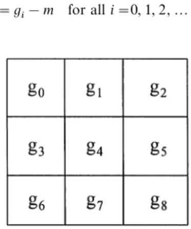
As shown in Fig. 1, we first divide the original image (gray-level data) into subimages of size n]n. The subimages are then processed one by one. For each subimage, we have to determine whether the proposed base-switching (BS) algorithm is worthy to apply to the subimage or not. In other words, if the
Fig. 3. Subimage A@. Each g@i is gi!m; i"0, 1,2,8. Fig. 2. An arbitrary given subimage A.
proposed BS will cause data explosion, i.e., will cause the b.p.p. (bits per pixel) be not less than 8 for this gray-level subimage, then we skip this subimage be-cause the whole subimage will be transmitted in the traditional pixel-by-pixel manner (n]n pixels, and each pixel has 8 bits). On the other hand, if the data explosion does not occur, then the proposed BS is used to transmit this subimage. Of course, an extra bit is needed to indicate whether the subimage is encoded (by the proposed BS) or not. (Therefore, the total number of bits needed to transmit a non-BS subimage is one more bit than that of the traditional pixel-by-pixel manner.) Throughout this paper, the subimage size used is 3]3 for the efficiency of compression ratio.
3.2. Encoding a subimage by BS
Given a 3]3 subimage A, whose nine gray values are g0, g1,2, g8 (see Fig. 2), define the ‘‘minimum’’ m, ‘‘base’’ b, and the ‘‘value-reduced subimage’’ A@ (see Fig. 3) of the subimage A by
m" min 04 i4 8gi, (1) b" max 04 i4 8gi! min04 i4 8gi#1, (2) A@ 3]3" A3]3!m]I3] 3, (3)
respectively. Here, each of the nine elements of I3]3is 1. Note that equation (3) means that
g@ i"
gi!m for all i"0, 1, 2,2, 8. (4)
Also denote that min 04
i4 8
g@i"0 and max 04
i4 8
g@i"b!1. (5) Therefore, the nine-dimensional vector A@"(g@0,g@1,2, g@8)canbetreatedasanine-digitnumber(g@0, g@1,2, g@8)b in the base-b number system. For convenience, let »3]3be the collection of all 3]3 subimage A@, and the base-set B"M1, 2, 3,2 , 256N. Then we define an integer-value function f : »3]3]BPMnon-negative integersN by
f (A@, b)"the decimal integer equivalent to the base-b number (g@0g@1,2, g@8)b "+8 i/0 g@i]bi (6) "(2((g@0]b#g@1)]b#g@2)]b#2) ]b#g@8. (7)
It is easy to prove the following two properties. Property 1. The inequality f (A@, b)(bN always holds. Here, N"n2 is the number of the pixels in the subim-age A@.
Proof. By equations (6) and (5), we have f (A@, b)"N~1+ i/0 g@i]bi4N~1+ i/0 (b!1)]bi "(b!1)N~1+ i/0 b@"(b!1)]bN!1 b!1 "bN!1(bN. K
Property 2. For each base b, and for each given integer j satisfying b!14j4+8i/0(b!1)]bi"bN!1, we can find a unique 3]3 A@ such that f (A@, b)"j.
Proof. Just convert the base-10 number (j)10 to
a base-b number (g@0g@1,2, g@8)b. Note that j5b!1 is required because equation (5) has confined the out-look of A@.
By Property 1, the number of bits needed to store the integer f (A@, b) using a binary number is therefore at most
Zb"vlog2 b9w. (8)
When we want to reconstruct A@"(g@0g@1,2, g@8), all we have to do is to switch that binary (base-2) number to a base-b number (g@0g@1,2, g@8)b.
3.2.1. Several possible ways to represent the subim-age A@ according to the value of base b. As stated in equation (5), for each subimage A@"(g@0g@1,2, g@8), we always have
minMg@0g@1,2, g@8N"0, (9) maxMg@0g@1,2, g@8N"b!1. (10)
Fig. 4. If the position of i.*/ and i.!9 are known, then only seven gray values needed to be encoded. Here, i.*/"3 and
i.!9"8 are known in this example.
1 bit 7 bits 8 bits 7 bits zJ b"vlog2 b7w bits
c b m P(min, max) binary equivalent of
(g@iD04i48, iOi.*/, iOi.!9)b Therefore, at least one of the pixels of A@ has gray
value 0, and at least one of the pixels of A@ has gray value b!1. There are at least two ways to store A@. The first way is as stated at the end of Section 3.1, namely, to store
b and a binary-equivalent of (g@0g@1,2, g@8)b. (11) The second way is to store
Mb; i.*/; i.!9N and MgiDiOi.*/, iOi.!9N. (12) (Here, i.*/3M0, 1,2, 8N is such that g@i.*/"0, and
i.!93M0, 1,2, 8N is such that g@i.!9"b!1. If more
than one i inM0, 1,2 , 8N have there g@i value 0, say, g@2"g@3"g@5"0, then use the smallest i as i.*/ (hence, i.*/"2 in this case). An analogous statement making i.!9 unique can be stated likewise.) We analyze below which of the two ways [(11) vs (12)] would save more storage space. First, we reduce (12) to a simpler form by Lemma 1 below.
Lemma 1. In the storage system (12), we can use 7 bits to indicate the positions of the pair (i.*/, i.!9). Proof. Because the size of the block A@ is 3]3, we have 04i.*/48 and 04i.!948. As a result, there are 9]8"72 possible combinations of the pair (i.*/, i.!9). Since 26(72(27, we can use 7 bits to indicate the combination (and hence, the location among the nine pixels) of (i.*/, i.!9) pair. K By Lemma 1, we know that equation (12) can be rewritten as
Mb; a 7-bit key to get (i.*/, i.!9)N,
and a binary-equivalent of the seven-digit base-b number (giDiOi.*/, iOi.!9)b. (13) To know when the storage system (13) can save more memory space than equation (11) does, we notice that first, both equations (13) and (11) needs to store b; second, equation (11) needsvlog2 b9w bits to repres-ent a nine-digit number g@0g@1,2g@8 in the base-b num-ber system, whereas equation (13) needs 7 bits to indicate the location of the (i.*/, i.!9) pair, and vlog2 b7w bits to encode a seven-digit number g@0g@1,2g@8 (with g@i
.*/ and g@i.!9 taken away) in the
base-b number system. [g@i
.*/and g@i.!9needs no storage
if we know the position of i.*/ and i.!9 (see Fig. 4), this is because g@i
.*/"0 and g@i.!9"b!1 always hold by
equations (9) and (10).] The next lemma and property are used to compare the storage system (11) and (13).
¸emma 2. (i). If b(23.5+11.314, then 7#log2b7'
log2 b9.(ii) If b'2
3.5+11.314, then 7#log2 b7(log2 b9. Proof. We first prove statement (i). Since b(23.5, we have log2 b(3.5, i.e. 2 log2 b(7; i.e. 9 log2 b! 7 log2 b(7, i.e. 9 log2 b(7#7log2 b, i.e. log2 b9( 7#7 log2 b. The second statement can be proved
like-wise. K
Property 3. Using the storage system (13) is more worthy than using the storage system (11) if and only if b'11.314.
The next concern is to find the condition such that using the storage system (11) or (13) is more worthy than using the ‘‘raw’’ storage system in which 9]8"72 bits are used to store the nine (original) gray values (each is 8-bit) and g0, g1, g2,2, and g8 of the subimage A. After careful checking, we obtain the following rules to encode a 3]3 subimage.
3.2.2. Format. There are three formats to be used in our proposed algorithm as follows:
Rule 1: If b3M1, 2,2 , 11N, then the coding format is 1 bit 7 bits 8 bits zb"vlog2 b9w bits
c b m binary equivalent of (g@0g@1,2,g@8)b
(This format uses at most 1#7#8#vlog2 119w"48 bits since b411.)
Rule 2: If b3M12, 13,2 , 128N, then the coding for-mat is
(This format uses at least 1#7#8#7# vlog2127w"49 bits and at most 1#7#8#7# vlog21287w"72 bits.)
Rule 3: If b3M129, 130,2 , 256N, then the coding for-mat is
1 bit 72 bits
c the original nine gray values: g0 , g1,2, g8 (This format always uses 73 bits.)
Note that c stands for the category-bit: if c is zero then we encode block A by Rule 1 or Rule 2 (accord-ing to the value of b); if c is one, however, Rule 3 is need. Also note that P(min, max) denotes which of the 9]8"72 possible position-pair is the actual position of the pair (i.*/, i.!9). As for (g@iD04i48, iOi.*/, iOi.!9)b, it is a seven-digit base-b number because the two gray values g@i
.*/and g@i.!9are taken away. Finally,
m"mini gi and b"maxi gi!mini gi#1 are as de-fined in equations (1) and (2), respectively. Below we explain why we use Rule 3 instead of Rule 1 or Rule 2 when b'128. If b5129, then using the format provided in Rule 1 is not worthy because 1#7#8#7# vlog2 b7w51#7#8#vlog2 1299w is longer than the fixed 73 bits needed in the format given in Rule 3. Similarly, if b5129, then 1#7#8#7# vlog2 b7w51#7#8#7#vlog21297w"73 implies that the format in Rule 2 cannot be better than that of Rule 3. Moreover, if b is large, say, b"200, then 1#7#8#7#vlog22007w"77 is even worse than the 73 required in the format of Rule 3.
We also give here another remark about Rules 1 and 2. Some readers might suggest that one more (sub-category) bit is used to distinguish Rule 1 from Rule 2; then, 4 bits (instead of 7 bits) are used to represent b for Rule 1 (whereas 7 bits are still used to represent b for Rule 2). However, according to our experiments, this modified approach was found not better than the old one which uses 7 bits to represent b for both Rules 1 and 2, especially if the hierarchical structure intro-duced in Section 3.4 was used. The only case that this modified approach [the one using one more (sub-category) bit to distinguish Rule 1 from Rule 2] could perform better occurred only when the hierarchical structure was not used and the image had many large smooth regions. However, since the hierarchical struc-ture can improve the compression ratio, and we wish to handle images of any kind without judging in advance whether the image has large smooth regions or not, we do not intend to use this modified approach. 3.3. Decoding
Without the loss of generality, we show below how to reconstruct (decode) the first subimage of an image which has been encoded using Rules 1—3 presented above in Section 3.2. (The remaining subimages can be reconstructed similarly.)
We first check the first bit c. If c"1, then we use the next 8]9("72) bits to reconstruct the nine gray values, each is 8-bit, of the subimage. However, if c "0, we use the next 7 bits to obtain the base value b. According to the value of b, there are two subcases to proceed.
Subcase 1: If b411, then we take the next 8 bits to obtain the value m; and after that, we take another vlog2 b9w bits of the received code to know the binary equivalent of (g@0g@12g@8)b. We can therefore obtain the nine gray valuesMg@iN8i/0 of the subimage A@. Then, with the help of equation (4), we can obtain the nine gray valuesMgiN8i/0 of the subimage A.
Subcase 2: If 124b4128, then get the next 8 bits, 7 bits, andvlog2 b7w bits, to obtain the values of m, P(min, max), and (g@iD04i48, iOi.*/, iOi.!9)b, re-spectively. With the help of a predefined position codebook, we can use the value of P(min, max), which is a codeword, to recover the positions of the two pixels where the (reduced) gray values g@i are minimum and maximum, respectively. By equation (4), the posi-tions where g@i become minimum or maximum are also the positions where gi become minimum or max-imum. Therefore, on the two pixels just recovered by the value of P(min, max), the ‘‘original’’ gray values gi should then be m and m#b!1, respectively, by equations (1) and (2). As for the remaining 9!2"7 pixels, we can use the nextvlog2 b7w bits to obtain a binary number. Convert thisvlog2 b7w-digit ber in the base-2 system to obtain a seven-digit num-ber in the base-b system. After adding the value m to each of these seven digits, we obtain the seven gray values needed.
3.4. Hierarchical use of the techniques introduced in Sections 3.2 and 3.3
The encoded result of Section 3.2 can be com-pressed further in a hierarchical manner. Consider 3]3"9 adjacent subimages, each subimage is of size 3]3. Then, since each subimage has its own base b, we have nine bases. (If some of these nine subimages were encoded using Rule 3, for convenience, just ‘‘as-sign’’ a fixed number to the corresponding bases.) In this paper, we set this fixed number as 128, and modify the base-value range of using Rule 2 as 12&127, so that we may completely discard the category bit ‘‘c’’ (see Section 3.2.2) for all subimages (because whether Rule 1 (or 2, or 3) is used to encode a specified subimage can be completely determined by the value of base). We then can imagine that there is a so-called ‘‘base-image’’, whose gray values are b0, b2, b2,2, b8; then, since it is a kind of image (except that each value is a base value of a subimage rather than a gray value of a pixel), we can use the technique introduced in Section 3.2 to compress these nine base values. The details are omitted.
Besides b, the minimal value m of each block can also be grouped and compressed similarly. In other words, for every 3]3"9 adjacent subimages, we
Fig. 5. A two-pass BS system. (a) 9]9 image S consists of nine subimages si (i"0, 1,2, 8), and each si is 3]3. (b) The base-subimage of S where bSimeans the base value of the
subimage si. (c) The minimum-subimage of S where msi
means the minimum-value of the subimage si. compress theirMm0, m1,2, m8N by treating m0&m8 as the nine gray values of an imaginary 3]3 ‘‘super’’ image. (If some of the 3]3"9 subimages that form the super image were encoded using Rule 3, the miss-ing mi can be arbitrarily assigned, because the decod-ing of those subimages usdecod-ing Rule 3 will not use mi at all.)
The compression layer described in the above two paragraphs are called Pass 2, and we can repeat the same procedure to encode in Pass 3 the result of Pass 2. Of course, the higher a layer is, the less the data to be processed.
For decoding, we first decode the highest pass, Pass k, using the method presented in Section 3.3, and then decode Pass k!1, and then decode Pass k!2, and so on.
Without the loss of generality, we only illustrate here the two-pass BS system (although three-pass will be used later in the experiments). Look at the 9]9 image S sketched in Fig. 5a. For Pass 1 encod-ing, nine 3]3 subimages s0&s8 are encoded by slightly modifying the non-hierarchical formats of Rules 1&3 given in Section 3.2.2. Note that there is no category bit ‘‘c’’; Rule 1 is still with 14b411; but Rule 2 is with 124b4127; and Rule 3 (which handles the case 1284b4256) now uses the artificial format
7 bits 8 bits 72 bits
b"128 m"an arbitrary number
The original nine gray values: g0, g1,2, g8 After that, each subimage drops the first 7#8"15 bits from its storage format by sending these 15 bits [a base-value b (7 bits) and a minimum-value m (8 bits)] to Pass 2 encoder. The base values of each nine adjacent subimages constitute a ‘‘super’’ image (see Fig. 5b), and the minimum values of each nine adjac-ent subimages also constitute a super image (see Fig. 5c). For Pass 2 encoding, these super images are encoded, respectively, using the original Rules 1&3 stated in Section 3.2.2.
For decoding, we first decode Pass 2, and recover the base subimage (Fig. 5b) and the minimum subim-age (Fig. 5c). We then decode Pass 1 according to these base values and minimum values. For example, 3]3 the subimage S0 in Fig. 5a is reconstructed with the help of the bs0ms0and just obtained. The original
image S (Fig. 5a) is thus recovered.
4. EXPERIMENTAL RESULTS AND COMPLEXITY ANALYSIS
Although the techniques introduced in Section 3 are explained in terms of gray-level images, we can of course use these techniques to handle color images by applying the techniques three times to each of the three color components.
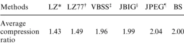
In this section, we use six color images (shown in Fig. 6) to test the proposed base switching (BS) algo-rithm. In order to compare our results with the results of JBIG and Lossless JPEG reported in reference (16), we used the same color components that was used in reference (16), i.e. we used the ‘‘YUV’’ components of the color images. All compression ratios presented below express the averages of the corresponding re-sults of the six images, and each of them is again the average compression ratio of the three color compo-nents (therefore, we took the average of 6]3"18 data sets to obtain a compression ratio). In the experi-ment, we used 3-pass BS algorithm (see Section 3.4) to compress each color image component, and the subimage sizes for each pass were 3]3. Table 1 shows the color image compression ratios for the LZ(27) (COMPRESS utility on UNIX), LZ77(27) (GZIP util-ity on UNIX), VBSS, JBIG, Lossless JPEG, and the proposed BS algorithms.
It was found that our BS algorithm could compete with VBSS and the two international standard algo-rithms JBIG and Lossless JPEG (their compression ratios are very close), and our method was superior to LZ and LZ77. In fact, we can see from Table 1 that the average compression ratio of the BS algorithm is a little better than that of the JBIG and a little inferior to that of the Lossless JPEG. Also note that, although the average compression ratio of the proposed three-pass BS method is a little [(2.04!2.00)/2.00"2%] inferior to that of the Lossless JPEG, the three-pass BS is about (5!4.43)/4.43+13% faster than the Lossless JPEG. [The single-pass BS is about (5!3.94)/ 3.94+27% faster than the Lossless JPEG.] In the encoding, for example, the single-pass BS algorithm requires about 3.33&4.55 clock cycles (the average is 3.94 clock cycles) for each pixel (we will analyze the detail in next paragraph), whereas the Lossless JPEG requires 4&6 clock cycles (the average is 5 clock cycles) for each pixel. On the average, the single-pass BS algorithm is therefore 27% faster than the Lossless JPEG. (The three-pass BS algorithm is 13% faster than the Lossless JPEG by a similar argument.) The reason that the Lossless JPEG requires 4&6 clock
Fig. 6. The test image set (actual size at 720]576 pixels/image).
cycles for each pixel is explained as follows: first, for each pixel, the Lossless JPEG requires 3&5 clock cycles for the predictor part [used for some arithmetic operations such as addition, subtraction, arithmetic-right-shift, and one’s complement operation; the detail is given in Section 2.10.3 of reference (28) and H.1.2.1 of Appendix A of reference (11)]; then one complete
clock cycle for the adaptive arithmetic coder part is needed [see Section 13.7 of reference (11)].
We discuss below in detail the time complexity of the BS algorithm. Without loss of generality, we only analyze the single-pass system (or the first pass of the hierarchical system). To encode a 3]3 subimage, we need 8&15 comparisons (eight comparisons for the
Table 2. A comparison of the encoding time* for VBSS method, S#P method, and BS method Average
encoding time (s) Methods
Images ½-component º-component »-component
(720]576) (320]576) (320]576)
VBSS 46.86 21.28 21.69
S#P 12.15 5.82 6.27
BS 3.56 1.84 1.84
*The encoding time does not include the I/O time because I/O are identical for all three methods. Table 1. The average compression ratio of the six test
images.
Methods LZ* LZ77s VBSSt JBIG° JPEG± BS Average
compression 1.43 1.49 1.96 1.99 2.04 2.00 ratio
*The Lempel-Ziv (Unix Compress) scheme. sThe LZ77 (Unix GZIP) scheme.
tThe program was provided by Ranganathan et al.(12). °JBIG (D0, P8, 3L, G).
±Lossless JPEG (T2, U1, L0, A).
best case and 15 comparisons for the worst case) to obtain min04
i4
8gi and max04 i4
8gi; 1 subtraction and 1 addition to compute the value of min04
i4 8! max04
i4
8gi#1 ["b, see equations (1) and (2)], and eight subtractions to obtain A@3]
3 [because we had known the location of min04
i4 8gi in the process of finding min04 i4 8gi and max04 i4
8gi, we could save 1 subtraction, see equation (4)]. After that, if Rule 1 (Rule 2) is applied, then we need eight (6) additions and eight (6) multiplications to compute equation (7). Since an arithmetic operation such as addition, sub-traction, comparison, shift, one’s complement, and multiplication could be accomplished during one complete cycle under the modern technology of VLSI [see Section 2.2 of reference (29)], the BS algorithm requires 30&41 clock cycles to encode a 3]3 subim-age. In other words, it takes 3.44&4.55 clock cycles to encode a pixel (the average is 3.94 clock cycles). On the other hand, because the encoded length of the JBIG, the Lossless JPEG, and our proposed algo-rithm are all variable instead of being fixed, we do not consider the computations of the transformation from decimal values to binary values, because this kind of computations are common for all three methods. Fi-nally, the job of decoding is similar to that of encod-ing, except that the computation of equations (1) and (2) now disappear. As for the computation loads needed in Passes 2 and 3, they are relatively negligible, because the whole image size of Pass 2 is only 1/(3]3)"19 of the whole image size of Pass 1; not to mention the even smaller image in Pass 3. [If we consider the work needed in Passes 2 and 3, the 3.94 clock cycles mentioned above will become 4.43 clock
cycles, which is about (5!4.43)/4.43+13% faster than the Lossless JPEG.]
We may also compare our BS method, which is a spatial domain method, with some other frequency domain methods developed recently. In the frequency domain approach, the performance of some recent lossless image compression methods based on EZW(1,20) algorithm are good. Said and Pearlmans’ work(15) called S#P-transform is a new and excellent technique that extended EZW. The average compres-sion ratio of S#P-transform (for the six test color images shown in Fig. 6) is about 2.18 and about 9% ["(2.18!2.00)/2.00] better than that of the posed method. However, to encode images, the pro-posed method is about three times faster than the S#P-transform in the encoding time (excluding the I/O time, which are identical for both methods). Table 2 illustrates the average encoding time of the VBSS, the S#P-transform, and the proposed BS algorithm for the ½, º, and » components of the six test color images. [The codec program of the S#P-transform provided by the authors of Said and Pearlman(15) can be obtained via anonymous ftp to the host ipl.rpi.edu, directory pub/EW—Code.]
5. CONCLUDING REMARKS
A new fast lossless compression algorithm in the spatial domain has been proposed along with the experimental results and time-complexity analysis. The compression ratios using the proposed BS algo-rithm were found to be superior to the UNIX-pro-vided methods LZ and LZ77, and competitive to VBSS and the international standard algorithms JBIG and Lossless JPEG. In addition, the encoding of the proposed method is three times faster than the EZW-based algorithm called S#P-transform, al-though S#P algorithm gains 9% more in compres-sion ratio. Also note that the encoding time of VBSS is about 11&13 times longer than ours. The math the-ory needed to derive the proposed encoding format is also provided.
In our experiments, we also tested some other subimage sizes such as 4]4, 6]6, and 8]8, and found that the subimages of size 3]3 can usually achieve higher compression ratios. The reason is that:
as the subimage size increases, the base value b (which indicates how wide the gray value variation of a subimage is) also increases, and the compression ratio is down because the frequency that Rule 3 occurs will increase. A future work might therefore be that: to segment the regions of an image into two classes, smooth vs. non-smooth, and then process the smooth (non-smooth) class using larger (smaller) subimage size. Of course, the success of this future work will depend on the careful consideration of the problems such as how to segment an image reasonably, how to record the segmentation result economically, and how to decide the subimage size automatically. Since this is a topic related to the so-called variable-size compres-sion, we do not discuss it here.
Acknowledgements—This work was supported by the Na-tional Science Council, Republic of China, under contract NSC 85-2213-E009-111. The authors wish to thank the ref-eree for valuable comments and suggestions. The authors also appreciate Dr Namuduri for mailing us the program of VBSS.
REFERENCES
1. J. M. Shapiro, An embedded hierarchical image coder using zero trees of wavelet coefficients, Proc. IEEE Data Compression Conf., pp. 214—223 (1993).
2. S. J. Lee, K. H. Yang, C. W. Kim and C. W. Lee, Efficient lossless coding scheme for vector quantization using dynamic index mapping, Electronics ¸ett. 31(17), 1426—1427 (1995).
3. CCITT (International Telegraph and Telephone Con-sultative Committee), Standardization of Group 3 Fac-simile Apparatus for Document Transmission, Recommendation T.4 (1980).
4. CCITT (International Telegraph and Telephone Con-sultative Committee), Facsimile Coding Schemes and Coding Control Functions for Group 4 Facsimile Apparatus, Recommendation T.6 (1984).
5. CCITT (International Telegraph and Telephone Con-sultative Committee), Progressive Bi-level Image Com-pression, Recommendation T.82 (1993).
6. ISO/IEC (International Organization for Standards/In-ternational Electrotechnical Organization), Progressive Bi-level Image Compression, International Standard 11544 (1993).
7. H. Hampel, R.B. Arps et al., Technical features of the JBIG standard for progressive bi-level image compres-sion, Signal Process.: Image Commum. 4(2), 103—111 (1992).
8. CCITT (International Telegraph and Telephone Con-sultative Committee), Digital Compression and Coding of Continuous-tone Still Images, Recommendation T.81 (1992).
9. ISO/IEC (International Organization for Standards/In-ternational Electrotechnical Organization), Digital Com-pression and Coding of Continuous-tone Still Images, International Standard 10918-1 (1993).
10. G. Wallace, Overview of the JPEG (ISO/CCITT) Still Image Compression Standard, Proc. SPIE (Image Pro-cessing Algorithms and ¹echniques), Vol. 1244, pp. 220—233 (1990).
11. W. B. Pennebaker and J. L. Mitchell, JPEG Still Image Data Compression Standard. Van Nostrand Reinhold New York (1993).
12. N. Ranganathan, S.G. Romaniuk and K. R. Namuduri, A lossless image compression algorithm using variable block size segmentation, IEEE ¹rans. Image Process., 4(10), 1396—1406 (1995).
13. V. N. Ramaswamy, K. R. Namuduri and N. Ranga-nathan, Lossless image coding using wavelets and vari-able block size segmentation, Proc. IEEE-SP Int. Symp. on ¹ime-Frequency and ¹ime-Scale Analysis, pp. 113—116 (1996).
14. O. Egger and M. Kunt, Embedded zerotree based loss-less image coding, Proc. IEEE Int. Conf. on Image Pro-cessing, pp. 616—619 (1995).
15. A. Said and W. A. Pearlman, An image multiresolution representation for lossless and lossy compression, IEEE ¹rans. Image Process. 5(9), 1303—1310 (1996).
16. R. B. Arps and T. K. Truong, Comparison of interna-tional standards for lossless still image compression, Proc. IEEE 82(6), 889—899 (1994).
17. A. G. Tescher, in ¹ransform Image Coding in Image ¹ransmission ¹echnique, W. K. Pratt, ed., Ch 4, Aca-demic Press, New York (1979).
18. H. G. Musmann, in Predictive Image Coding in Image ¹ransmission ¹echniques, W. K. Pratt, ed., Academic Press, New York (1979).
19. G. G. Langdon, Sunset: a hardware-oriented algorithm for lossless compression of grey-scale images, Proc. SPIE (Medical Imaging »—Image Capture, Formatting, and Display), Vol. 1444, pp. 272—282 (1991).
20. J. M. Shapiro, Embedded image coding using zerotrees of wavelet coefficients, IEEE ¹rans. Signal Process. 41(12), 3445—3462 (1993).
21. S. G. Mallat, A theory for multiresolution signal de-composition: the wavelet representation, IEEE ¹rans. Pattern Anal. Mach. Intell., 11(7), 674—693 (1989). 22. W. R. Zettler, J. Huffman and D. C. P. Linden,
Applica-tion of compactly supported wavelets to image compres-sion, Proc. SPIE (Image Processing Algorithm and ¹echniques), Vol. 1244, pp 150 —160 (1990).
23. O. Rioul and M. Vetterli, Wavelets and signal process-ing, IEEE Signal Process. Mag., 14—38 (1991). 24. R. A. Devore, B. Jawerth, and B. J. Lucier, Image
com-pression through wavelet transform coding, IEEE ¹rans. Inform. ¹heory 38(2), 719—746 (1992).
25. M. Antonini, M. Barlaud, P. Mathieu, and I. Daub-echies, Image coding using wavelet transform, IEEE ¹rans. Image Process., 1(2), 205—220 (1992).
26. J. W. Woods, ed., Subband Image Coding, Kluwer, Bos-ton, MA (1991).
27. J. Ziv and A. Lempel, A universal algorithm for sequen-tial data compression, IEEE ¹rans. Inform. ¹heory IT-23, 337—343 (1977).
28. V. Bhaskaran and K. Konstantininides, Image and »ideo Compression Standards: Algorithms and Architectures. Kluwer Academic Publishers, Boston (1995).
29. J. L. Hennessy and D. A. Patterson, Computer Architec-ture a Quantitative Approach, Morgan Kaufmann, San Mateo, California, Third printing (1993).
About the Author—TREES-JUEN CHUANG was born on 15 December 1970 in Taipei, Taiwan, Republic of China. He received his B.S. degree from Soochow University in 1992, Taiwan. Since 1993 he is a Ph.D. candidate in the Computer and Information Science Department of National Chiao Tung University. His recent research interests include pattern recognition, image processing and image encryption.
About the author—JA-CHEN LIN was born in 1955 in Taiwan, Republic of China. He received his B.S. degree in computer science in 1977 and M.S. degree in applied mathematics in 1979, both from National
Chiao Tung University, Taiwan. In 1988 he received his Ph.D. degree in mathematics from Purdue University, U.S.A. During 1981—1982, he was an instructor at National Chiao Tung University. From 1984 to 1988, he was a graduate instructor at Purdue University. He joined the Department of Computer and Information Science at National Chiao Tung University in August 1988, and is currently a professor there. His recent research intersts include pattern recognition, image processing, and parallel computing. Dr Lin is a member of the Phi-Tau-Phi Scholastic Honor Society, the Image Processing and Pattern Recognition Society, and the IEEE Computer Society.


![Fig. 5. A two-pass BS system. (a) 9 ]9 image S consists of nine subimages si (i"0, 1,2, 8), and each si is 3]3](https://thumb-ap.123doks.com/thumbv2/9libinfo/7688471.142934/6.735.40.348.848.1016/fig-pass-bs-image-s-consists-subimages-si.webp)