國 立 交 通 大 學
資訊科學與工程研究所
碩 士 論 文
應用層多播網路之即時影音串流設計
The Design of Live Video Streaming Using Application Layer
Multicast
指導教授:張明峰 教授
研 究 生:張博今
應用層多播網路之即時影音串流設計
The Design of Live Video Streaming Using Application
Layer Multicast
研 究 生: 張博今
Student: Po-Ching Chang
指導教授: 張明峰教授
Advisors: Prof. Ming-Feng Chang
國 立 交 通 大 學
資 訊 科 學 與 工 程 研 究 所
碩 士 論 文
A Thesis Submitted to
Department of Computer Science and Information Engineering
College of Electrical Engineering and Computer Science
National Chiao Tung University
in Partial Fulfillment of the Requirements
for the Degree of Master
in
Computer Science and Information Engineering
June 2007
Hsinchu, Taiwan, Republic of China
應用層多播網路之即時影音串流設計
學生:張博今
指導教授:張明峰 博士
國立交通大學資訊工程學系(研究所)碩士班
中文摘要
近年來使用者對多媒體的需求帶動播放,擷取及傳輸設備快速普及,加上各種寬頻 網路的佈建,使得隨時隨地透過網路與他人分享即時影音成為可能。本論文著重於設 計一個可讓使用者建立頻道分享即時擷取的影音,並可在多個頻道間切換收看的平台。 我們參考多種即時影像於網路傳輸的模式,IP Multicast 普遍被網際網路提供商用 來提供 triple play 服務(即電話、電視及網路三項服務共構),但其需要特殊的多播 路由器的支援,對業者來說建置系統的門檻也相對高出許多。許多研究都把重心移到 應用層的多播,利用上層資料結構記錄群組成員及傳送路徑。目前即時串流的應用層 多播解決方式分為雙層架構與點對點架構。其最大的共同點是由來源端建立起一棵多 播樹並且擔任管理的工作。 本篇論文提出一些改良方法。我們以混合式點對點網路架構建立的應用層多播網路 將即時影音傳輸至各個使用者。頻道中的使用者被組織成一棵多播樹,每個節點記錄 此傳播樹上的一些成員節點,當加入/離開頻道或其父節點離開時,都由節點自行處 理,此舉可減少來源端的負荷,並且將系統負荷平均分散到使用者身上。此外,當使 用者暫時離開頻道時,這些成員節點的記錄會暫存下來用以縮短重新加入此頻道所需 花費的時間。The Design of Live Video Streaming Using Application
Layer Multicast
Student: Po-Ching Chang
Advisor: Dr. Ming-Feng Chang
Department of Computer Science and Information Engineering
National Chiao Tung University
Abstract
In the recent years, the need of multimedia services promotes appliances, such as MP3 player, digital camera, and digital video, become more and more popular. On the other hand, the distribution of many types of access networks makes it possible that users can share their live video streaming at any time and any where. This thesis focuses on designing a platform where users can create channels to share their streaming and switch between these channels to watch the shared streaming.
We studied many real-time streaming delivering solutions, and the IP Multicast is proposed by many ISPs to construct triple-play service (the combination of the television, telephone, and high-speed internet access services). However, the IP Multicast needs the supports of special network equipment – multicast routers. This increase the building cost for the service providers. Today, most of research in multicast has been moved to application layer. The group members and delivery path are kept in the application layer. The solutions classified into two-tier and peer-to-peer architecture. The common point of these solutions is that the source node builds a multicast tree and serves as a manager of the tree.
tree based on a hybrid peer-to-peer model to deliver streaming content to every user. The users in a channel are organized as a multicast tree and every node keeps information of some member nodes on the multicast tree. When a node joins/leaves a channel or when its parent node leaves, the node can use the information to handle these events. Therefore, the burden of a channel can be dispersed to every participant. Moreover, the kept information is used to reduce the rejoining latency after a user departs a channel temporarily and switches back.
誌謝
首先感謝我的指導老師張明峰教授。這兩年在老師費心的指導下,學生方能順利 完成此篇論文。於受業期間,老師對於思路清晰及方法明確尤為重視,也令學生獲益 良多。在此衷心表達最誠摯的謝意。 特別感謝孟達學長於論文中的指導與建議,實驗室的同學與學弟們這兩年來在學 業及生活上的幫助及鼓勵。也感謝孟容一路來對我的關懷。 最後謹將此篇論文獻給我的家人 ─ 母親、爺爺、奶奶及東文姑姑,給予我全心 全力的支持,使我能專心完成研究。Tables of Contents
中文摘要...I ABSTRACT ... II 誌謝...IV CHAPTER 1 INTRODUCTION... 1 1.1 INTRODUCTION... 1 1.2 RELATEDWORKS... 2 1.3 OBJECTIVES... 41.4 OVERVIEW OF THIS THESIS... 5
CHAPTER 2 BACKGROUND ... 6
2.1 UNICAST VS. MULTICAST... 6
2.1.1 IP Multicast... 6
2.1.2 Overlay Multicast... 8
2.2 PEER-TO-PEERNETWORK... 9
2.3 SIP (SESSIONINITIATIONPROTOCOL)... 10
2.4 SDP (SESSIONDESCRIPTIONPROTOCOL)... 11
2.5 RTP ... 12
2.6 SUMMARY... 13
CHAPTER 3 THE DESIGN OF OUR SYSTEM ... 14
3.1 SYSTEMARCHITECTURE... 15
3.1.1 Data Structures ... 16
3.2 CIS (CHANNELINFORMATIONSERVER)... 17
3.3 LSP (LIVESTREAMINGPEER) ... 20
3.3 START UP ANDJOIN ACHANNEL... 21
3.4 NODEDISCONNECTION... 24
3.4.1 Graceful Departure... 25
3.4.2 Ungraceful Departure... 25
3.5 CHANNELSWITCHINGMECHANISM... 27
CHAPTER 4 SYSTEM IMPLEMENTATION... 29
4.1 THEIMPLEMENTATION OFCIS... 29
4.2 THEIMPLEMENTATION OFLSP ... 31
CHAPTER 5 CONCLUSIONS ... 33
List of Figures and Tables
Figure 1-1 The architecture of Scattercast...3
Figure 2-1 IP Multicast service model...7
Figure 2-2 Overlay Multicast service model ...8
Table 2-1 RTP Header Format ...12
Figure 3-1 Architecture of our system...15
Table 3-1 The information of a peer stored by the CIS and peers ...17
Figure 3-2 (a),(b) The example of adding and deleting records ...18
Figure 3-2 (c) The example of channel switching ...18
Figure 3-3 The relation between the size of a partial list and the member list...20
Figure 3-4 Register a channel ...22
Figure 3-5 The signaling flow of peer join a channel...22
Figure 3-6 Call redirected by selected node ...24
Figure 3-7 1.a - 1.b The sub-tree is kept by a child node of the leaving node ...26
Figure 3-7 2.a – 2.c All nodes in the sub-tree will be notified recursively...26
Figure 3-8 Message flow of channel switching...28
Figure 4-1 The processing flow chart of the CIS ...30
Chapter 1
Introduction
1.1
Introduction
The growth of the Internet has been changing people’s habits in an inestimable speed. Traditional services have been translated into “e-services”, such as e-mail, e-paper, e-payment, etc. The Internet has become the most direct way that people who want to know about weather or working opportunities will access. The burgeoning bandwidth and processing power create many innovative applications which bring us more convenience and can share our experiences to others around the world easily. Besides, with the wireless technology expanding the access ability of the Internet, we can write down words, take pictures or record video any time and publish them right away.
In the meanwhile, VoIP is considered as the recommended solution for the next generation telecommunication. Not only the telephony services but also the broadcasting radio or cable television will be totally changed by this new network technology. It means that almost our daily life could not depart from the Internet. We believe that the live multimedia streaming over IP network will be a potential application that can catch the user’s attention and stimulate more users to join it.
Although MBone[1] , a IP layer multicast solution, provides a pretty good method to transmit streaming data through IP network, it also has a big constraint limiting its usage. There is no standard or particular organization to manage the IP multicast group address, so the probability of IP confliction will rise when more users create live streaming services. Hence, we try to use Application Layer Multicast (ALM) to construct a platform where users can create their own channels to show live stream captured from their video cameras.
1.2
Related Works
There are many types of delivery architectures providing solutions for broadcasting live Audio/Video streaming. One of them is based on a powerful source server or a cluster of servers that receivers can subscribe the service and receive streaming data from. ICEcast [2], an open source project developed by this architecture, has been downloaded by lots of users. The defect of this solution is the lack of scalability and sudden peeks may lead the disruption. The source provider has to prepare a powerful server with lots of bandwidth to serve the streams for a lot of people, because the need of the bandwidth is linear related to the number of subscribers.
In order to improve the system scalability and reduce bandwidth requirements, multicast approaches have been proposed to reduce the amount of duplicated packet transmissions over the Internet and the burden of the source providers. The overlaid network multicast, which essentially consists of some well-organized or dynamically arranged super nodes, is different from the IP-Multicast solution that we described above. Peer-to-peer multicast trees, such as end system multicast [3] or chunk-driven P2P streaming [4, 5], are recently the most popular architectures. Typically, the nodes organize themselves into an efficient overlay tree and forward data.
Peercast [6] uses P2P technologies to make each participating node become a
broadcaster without the costs of traditional streaming. The source should handle the whole distribution tree and process the participations, departures or failure events of the nodes. When a user subscribes to receive streaming, the source will randomly pick a node to serve the user. This is useful and easy to setup for a small group sharing live streaming, but an embedded device such as mobile phone or PDA may not tolerate the sudden peeks of workload increasing.
Un icas t Co nne ctio n T h e In te rn e t S C X S C X S C X c lie n t c lie n t c lie n t c lie n t c lie n t M u ltic a s t g ro u p U n ic a s t C o n n e c tio n Un icas t Co nne ctio n T h e In te rn e t S C X S C X S C X S C X S C X S C X c lie n t c lie n t c lie n t c lie n t c lie n t M u ltic a s t g ro u p U n ic a s t C o n n e c tio n
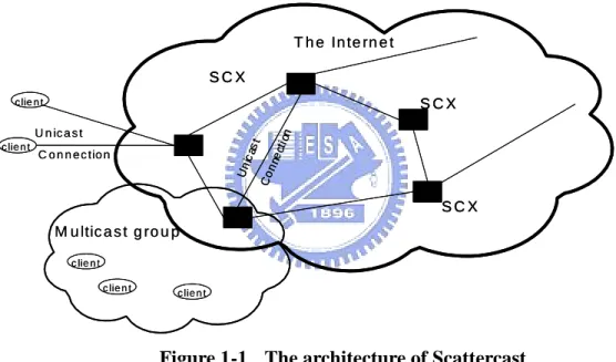
Scattercast [7] is composed by three components. Figure 1-1 shows the architecture of
scattercast. The source provider and receiver are implemented on a client and SCXs (Scatter-Cast proXy) are the specific network nodes that construct an overlaid network on the internet. A client which wishes to participate in the scattercast session communicates with the nearby SCX and served by that SCX. The role of SCX is a super node of a two tier overlay network. Scattercast needs ISP’s proxy servers to play as the media relay servers. This is expensive and not easy to be constructed by a small company.
Figure 1-1 The architecture of Scattercast
SplitStream [5] is designed for high-bandwidth data spreading. It stripes the data across
multicast trees to balance the uploading/downloading traffic ratio of each node. This method also reduces the influence of any single node whose failure can only lead to the interruption of one tree. All of N nodes take their role as a serving node in one tree, and a leaf node in the other N-1 trees. Each peer gives back to the network as many bandwidths as it consumes. However, the tree construction cost is high, a streaming description method, such as MDC (Multiple Description Coding) to identify each streaming part, is needed and the delay of each
tree are not stable for real-time application.
However, those existing multicast approaches only focused on how to construct and maintain a network topology to deliver packets from a source provider to the subscribers. However, like watching TV programs, more choices will encourage users to switch channels to get different stuffs. Streaming services should enable users to depart from the original channel and join another one. When users traverse between some favorite channels, the latency of joining the delivering trees should be minimized. In this paper, we design a fast switching mechanism to solve this problem.
1.3
Objectives
In the thesis, we target on the "live video streaming sharing" from many source providers to a dynamic, large number of receivers. The first issue we addressed in the thesis is to develop a live streaming system that includes many content delivery multicast trees and the management policy for dynamic events such as user departure or node failure.
The root of each tree is a source provider that sends his streaming data by an ALM network. Peers can subscribe a streaming service (channel) through a well-known channel information server. Like many P2P system, it’ll send back a peer list and update the status about this channel. Peers use the list to be initiating information to associate with other peers. All users can voluntarily become a source provider and others may subscribe to receive/relay streaming data at any time. We also propose a simple mechanism to reduce the latency when users switch between their favorite channels.
1.4
Overview of this thesis
The remaining of the thesis is organized as follows. In Chapter 2, we describe the background of live streaming service. In Chapter 3, we present the architecture and the design of our system. The implementation and conclusions are shown in Chapter 4 and Chapter 5.
Chapter 2
Background
In this thesis, we design a live video streaming platform on the IP network. Every node can start up a channel to publish live video captured by its device or received from other nodes. Therefore, we first introduce two multicast technologies and basic types of peer-to-peer networks in this chapter. Second, we introduce the basic concepts of VoIP and some proposed standard protocols.
2.1
Unicast vs. Multicast
In computer networks, unicast is the transmission of packets to a single destination and Multicast which sends to a group of members is used to improve the efficiency of broadcasting. They are all derived from “broadcast”. The unicast server provides a stream to a single user at a time, while the multicast server can support large audiences by serving content simultaneously to multiple users.
Multicast is using the most efficient strategy to transmit messages over each link only once and creating copies only when the routing paths split. It is an efficient mechanism to support group communication. It decouples the size of the receiver set from its amount of kept states and potentially avoids redundant communications in the network.
2.1.1
IP Multicast
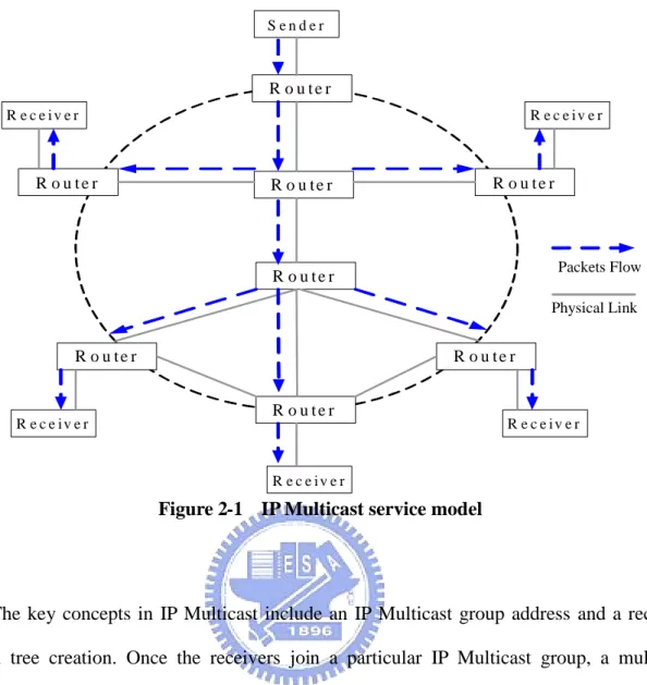
IP Multicast [1] is an implementation of multicast on IP routing level, where routers creates a spanning tree for sending packets in real time. Figure 1-1 shows the IP Multicast service models.
Figure 2-1 IP Multicast service model
The key concepts in IP Multicast include an IP Multicast group address and a receiver driven tree creation. Once the receivers join a particular IP Multicast group, a multicast distribution tree is constructed for that group. MBone uses network of mrouters that can support IP Multicast and enable access to real-time interactive multimedia on the internet. It uses IGMP (Internet Group Management Protocol) for session registration and 224.2.0.0 IP address for multimedia conferencing.
However, the IP Multicast model requires routers to maintain the states for each group inside the network. This will cause much higher complexity than the IP unicast model of best-effort delivery and violate the “stateless” design principle of routers. Also, there was not any mechanism demonstrated that would allow the IP Multicast model to scale to thousands of senders and multicast groups. For both these two reasons and other economic concerns, IP Multicast is not in general use in the commercial Internet.
R o u t e r R o u t e r R o u t e r R o u t e r R o u t e r R o u t e r R o u t e r R o u t e r S e n d e r R e c e i v e r R e c e i v e r R e c e i v e r R e c e i v e r R e c e i v e r Physical Link Packets Flow
2.1.2
Overlay Multicast
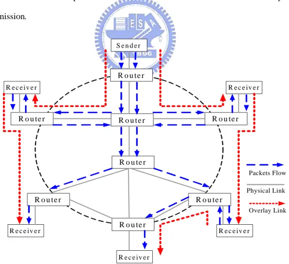
The limitation of IP Multicast deployment leads great interest to find alternative approaches that are implemented at the application layer, using only end-systems. The Application Layer Multicast does not require any kind of special support by the operating system install on the host. In an overlay multicast approach, Participating nodes organize themselves into an overlay topology for delivering messages. Each edge in this topology corresponds to a unicast path between two nodes in the best-effort IP network. Figure 1-2 shows the Overlay Multicast service model.
All multicast related functionality is implemented at the nodes instead of at routers, and the goal of the multicast protocol is to construct and maintain an efficient overlay for data transmission.
Figure 2-2 Overlay Multicast service model
R o u te r R o u te r R o u te r R o u te r R o u te r R o u te r R o u te r R o u te r S e n d e r R e c e iv e r R e c e iv e r R e c e iv e r R e c e iv e r R e c e iv e r Physical Link Packets Flow Overlay Link
2.2
Peer-to-Peer Network
The peer-to-peer (P2P) network has become the most popular research topic in computer network. Many types of system architecture were declared that they have some characteristics which adapt to the applications with millions of users involved.
An important goal in P2P networks is that all clients provide resources, including bandwidth, storage space, and computing power. Thus, when nodes arrive and request on the system increases, the total capacity of the system also increases. But it is very difficult to achieve for client-server architectures with a fixed number of servers. In these systems, adding more clients also means slower data transfer rate for all users. P2P network is also known for its flexibility, robustness and fault tolerance by reproducing data over multiple peers and enabling peers to find the data with or without an index server.
These features not only suit to file sharing applications where the files are stored on and served by many participating nodes but also have a good fit to live video streaming multicast systems that people provide their video to hundreds of receivers simultaneously. Usually, P2P systems depend on all the nodes play the roles of both servers and clients in place of central servers. According to their degree of centralization, the P2P systems are divided into two classifications: pure P2P and hybrid P2P. [8]
In pure P2P networks, there are no central servers managing the network and no central routers reminding the paths (The overlay links are established arbitrarily). Such networks can be easily constructed while a new peer which wants to join the network can copy existing links of another node and then transform to its own links. On the opposite side, hybrid peer-to-peer networks have at least one central server that keeps some information about peers and responds to requests for the information.
2.3
SIP (Session Initiation Protocol)
Session Initiation Protocol [9, 10] was developed by the SIP working group within IETF. It is an application-layer control protocol for initiating, managing and terminating multimedia sessions with one or more participants. SIP has been defined on RFC 2543, modified on RFC 3261 and has many extensions for some special purposes like specific event notification (RFC 2543) and instant messaging and presence leveraging (SIMPLE – RFC 3428). SIP is a text based protocol that modified from HTTP. There are four components participating in SIP: user agent, registrar, SIP Proxy server and SIP redirect server.
User agent is usually the hardware device or software of users for initiating and
terminating sessions. It includes the client part and server part. The UAC sends SIP requests to the UAS directly or through one or more proxy servers. The UAS replies the response to any SIP request.
Registrar is a location server that keeps each node’s contact information within their
assigned network domain queried by proxy or redirect server.
Proxy server is an intermediate entity responsible for forwarding the requests and
responses to user agents or next proxy server.
Redirect server responds a caller’s SIP request with the callee’s real location (in the
form of SIP URL).
In this thesis, we will use user agents, redirect server and enhanced registrar to implement our live video streaming system.
2.4
SDP (Session Description Protocol)
Session Description Protocol [11, 12] is a format for describing streaming media initialization parameters. It has been published by the IETF as RFC 2327 and modified many times. The latest version is RFC 4566. SDP is intended for describing multimedia sessions for the purposes of session announcement, session invitation and other forms of session initiation. There are five terms related to a SDP:
Conference is a set of two or more communicating users along with the software they
are using.
Session is the multimedia sender and receiver and the flowing stream data.
Session Announcement is a mechanism by which a session description is conveyed to
users in a proactive fashion.
Session Advertisement is same as Session Announcement.
Session Description is a well defined format for conveying sufficient information to
discover and participate in a multimedia session.
A session initiator may support many kinds of media types (voice/video/text/ … ). Therefore, the description of a session need to make a list of these supported types and the specification of a number of parameters for each media stream. Parameters are divided into two classes: session level parameters and media level parameters. Session level parameters include information such as the name of this session, the originator and the time that session is to be active. Media level parameters include the media type, port number, transport protocol, and media format.
SIP uses SDP in an answer/offer mode (RFC 3264). A caller sends an “INVITE” carried an SDP description that describes the set of addresses, and ports and media formats that a caller is willing to use in its message body. This set of formats comprises an offer by the
calling party and the called party will send back a response with another SDP description includes an accepted offer or each rejection of the media format listed above. The result of the negotiation between two parties is an agreement of type and format they willing to use.
2.5
RTP
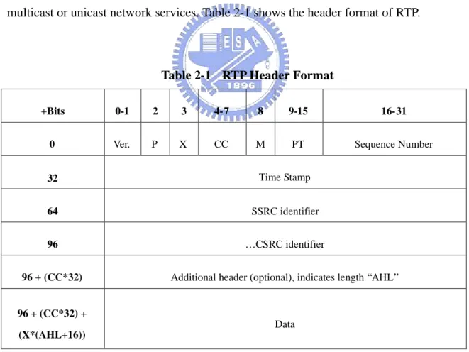
The Real-time Transport Protocol [13, 14] defines a standardized packet format for delivering audio and video over the Internet. It was developed by the Audio-Video Transport working group of the IETF and first published in 1996 as RFC 1889 which was made obsolete in 2003 by RFC 3550. RTP provides end-to-end network transport functions suitable for applications transmitting real-time data, such as audio, video or simulation data, over multicast or unicast network services. Table 2-1 shows the header format of RTP.
Table 2-1 RTP Header Format
+Bits 0-1 2 3 4-7 8 9-15 16-31
0 Ver. P X CC M PT Sequence Number
32 Time Stamp
64 SSRC identifier
96 … CSRC identifier
96 + (CC*32) Additional header (optional), indicates length “AHL”
96 + (CC*32) + (X*(AHL+16))
Data
prevent the out-of-order delivery. It was originally designed for multicast protocol, but has been applied in many unicast applications. The structure of a RTP packet is shown above. The RTP header contains information related to the payload such as the source, size, encoding type etc. However the RTP packet can’t be transferred directly over the network. For transferring, it should cooperate with UDP or TCP and IP.
The Real-time Transport Protocol and the Real-time Transport Control Protocol (RTCP) are commonly used together. RTP is used to transmit data and RTCP is used to monitor QoS. The monitoring of quality of service provides information about reception quality which the application can use to make local adjustment. For example if congestion is detected, the application could decide to lower the data rate or build another connections to other backup nodes.
When audio and video sessions are going at the same time, sessions will not be sent together but separated for each media type. The main advantage of this separation is to make it possible to receive only one part of the transmission, commonly audio data, which lowers the total bandwidth.
2.6
Summary
In this thesis, we will design a video streaming platform that uses a hybrid peer-to-peer architecture to enable users to find each other on the internet. We use SIP/SDP to implement user registration and session initiation, and RTP to deliver audio/video data over the Internet.
Chapter 3
The Design of Our System
Our live video streaming platform provides users a convenient interface where they can share their video streaming, receive video streaming, and switch between these streaming efficiently. We call a live video streaming service provided by a user of our system as a “channel”. There are three principles in designing our system: (1) balance the loading of the video source provider and participating nodes; (2) find and contact a nearby member node of the channel chosen by the user to relay streaming data; (3) reduce the response time when users join or switch to a channel and the recovery latency when a node’s ancestor leaves from a channel.
To balance the loading of all nodes, we construct our system based on a hybrid peer-to-peer network model where each node finds information of all streaming from a well-known server and receives streaming data from a self-constructed application layer multicast tree. The basic idea of our system is that a node gets a channel list from the server where the providers register channels. A user can subscribe a channel at one time and the server provides a number of member nodes as entry points of this channel for the user.
Each node stores the information of some members of the channels that the user is interested in. When the user switches channels or when the node’s ancestor leaves, the member information is used to find a contact point. If the member information is invalid (out-of-date), the node request a new member list from the server. The member information is very important for achieving our goal, especially in reducing the response time and the recovery latency. The remaining section describes our system architecture and the usage of the member information in details.
3.1
System Architecture
As we described before, the whole system consists of a Channel Information Server (CIS) and the Live Streaming Peers (LSP). A LSP can create a channel (by registering a service to the server) to share its video streaming. A LSP can also subscribe service to receive streaming content by contacting other clients who have joined earlier. The main protocol of our system is based on SIP with extensions such that it can support call forwarding to build a multicast tree.
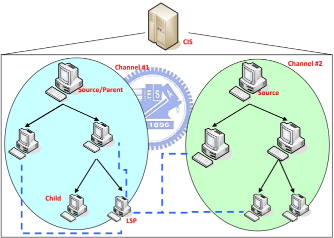
Figure 3-1 Architecture of our system
The system architecture is illustrated in Figure 3-1. There are two channels registered on the CIS. Both channels have five members who form two multicast trees. The bold arrows indicate the streaming paths from the root to other receivers. The dotted lines represent the member list of each channel stored on client LSP. When a new incoming node wants to join a
CIS Channel #2 Source Channel #1 Source/Parent Child LSP
channel, it contacts the CIS first to get a partial list of existing member nodes which could relay media data. Afterward, it measures the network latency between these nodes and itself, and then contacts the best one for relaying media. The new incoming node stores the member list which can be used later when the chosen serving node leaves this channel or when the node switches back to this channel.
3.1.1
Data Structures
For every channel, there are two types of member lists in our system. One is maintained by the CIS and another by participating nodes. With different usages, they have different requirements and features. The list on the server is queried frequently; therefore the CIS should ensure its accuracy so that most of the peers in the list can serve for new subscribers. On the other hand, the maintenance overhead on each peer should not lead to the deterioration of service.
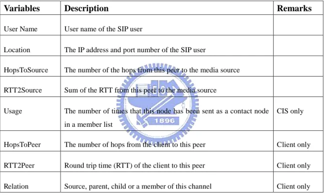
Table 3-1 shows the information of each record in a member list, and a member list is composed by a number of records. Every records include the location (IP address and port
number) and network measurement results such as the number of hops (HopsToSource) and
round-trip time (RTT2Source). These results are reported to server by the node itself. The values of the results are the summation of overlay network latency through its ancestors. The “Usage” is a parameter used only by the CIS to count the numbers of peers that have received a partial member list with this node.
A User node may also maintain the member lists of channels that it often subscribes to. The data structure of these lists is very similar to the server’s but without “Usage” information. The information will be transferred in SIP request/response by adding them as parameters of
but the “HopsToPeer” and “RTT2Peer” variables are measured after the node parse the others from SIP message sent by the CIS or other nodes. The data structure of client side adds “Relation” variable that illustrates the relationship between the user node and this member. These lists will be updated by a set of hello and echo messages between users. And if the node found a list is out-of-date, it would request a new one from the CIS.
Table 3-1 The information of a peer stored by the CIS and peers
3.2
CIS (Channel Information Server)
The CIS is the key component in our system. It is an entry point for a user to discover all channels and get the member list of each channel. Each service must be registered with the CIS before the service is published. The CIS acts as a combination of a SIP registrar and redirect server. The CIS creates and maintains a member list when a channel registered by a
Variables Description Remarks
User Name User name of the SIP user
Location The IP address and port number of the SIP user
HopsToSource The number of the hops from this peer to the media source
RTT2Source Sum of the RTT from this peer to the media source
Usage The number of times that this node has been sent as a contact node in a member list
CIS only
HopsToPeer The number of hops from the client to this peer Client only
RTT2Peer Round trip time (RTT) of the client to this peer Client only
user. Upon receiving an “INVITE” request from a LSP, the CIS looks up the member list of the channel and picks up some to constitute a contact list.
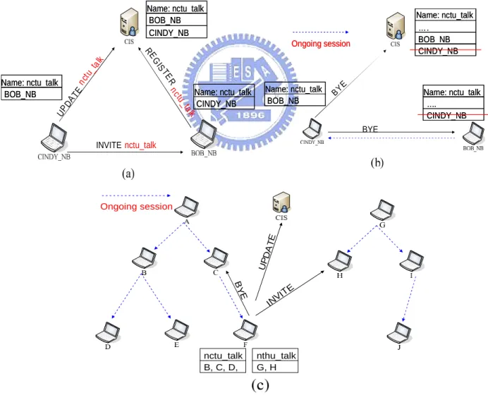
There are three conditions in which the CIS adds a record to the member list of a channel and also three conditions for deleting records. An example of these cases is illustrated on Figure 3-2. First of all, when a LSP sends a REGISTER request to open a channel, it is added into the list of the channel. Second, as a LSP finds a parent node to be served, it sends a UPDATE message to the CIS and a record describing its relation will be added. The last one is about channel switching. For the CIS, channel switching involves two records that one is deleted from the origin channel and another is added to the target channel.
Figure 3-2 (a),(b) The example of adding and deleting records Figure 3-2 (c) The example of channel switching
RE G IS TE R nctu _talk UP D A TE nctu _tal k Name: nctu_talk BOB_NB CINDY_NB Name: nctu_talk BOB_NB CINDY_NB INVITEnctu_talk BOB_NB Name: nctu_talk BOB_NB Name: nctu_talk CINDY_NB Name: nctu_talk CINDY_NB Name: nctu_talk Ongoing session Ongoing session Name: nctu_talk BOB_NB CINDY_NB … . Name: nctu_talk BOB_NB CINDY_NB … . BYE BY E Name: nctu_talk BOB_NB Name: nctu_talk
BOB_NB Name: nctu_talk… . CINDY_NB Name: nctu_talk … . CINDY_NB nctu_talk nthu_talk B, C, D, G, H B Y E INVI TE UP DA TE Ongoing session
A record of a member list is deleted when a participating node leaves the channel or when the CIS considers that one member node has low a probability to serve others. In general, a node’s departure is notified by the leaving node itself or its relative nodes (its parent or children). When the CIS receives the notice, the member’s record is deleted from the member list. In order to keep the efficiency of peer joining process, the CIS counts the number of times that a member has been sent as a record of a partial list.
Besides, we assume a node that has stayed in a channel longer is more stable, i.e., it will stay longer. Therefore, all nodes on a member list maintained by the CIS had joined this channel for a period. On the other hand, when a member list grows with the number of participants, the nodes who have been contacted many times are relatively useless, because they have little bandwidth to serve other nodes. Hence the CIS deletes these nodes from the member list.
The CIS runs a selection algorithm constituting member nodes in the member list to a partial list. By the research results of Information System Laboratory, Stanford University [15], the CIS adjusts the size of the partial list sent to a joining peer according to the current size of the member list to reduce the control overhead. At the beginning of a channel, the size of a member list is small, and the size of a partial list is a half of the member list. When the size of the member list is larger than ten, the size of a partial list increases logarithmically. Figure 3-3 shows the relation between the size of a partial list and a member list.
The selection algorithm is simple that the CIS sorts all nodes in the member list by “HopToSource” and chooses the nodes which have the smallest value. By this selection algorithm, a new incoming node contacts with member nodes near by the source, so the multicast tree is constructed close to a balanced tree which decreases the influences of a single node’s leaving.
0 1 2 3 4 5 6 7 8 9 1 2 5 10 20 50 100 200 500 1000
the size of the member list the size of a partial list
Figure 3-3 The relation between the size of a partial list and the member list
3.3
LSP (Live Streaming Peer)
Users use the LSP to receive and distribute streaming data, and play out the audio/video that the user subscribed from the server. It is an enhanced SIP UA supporting further functionalities needed in our system. Like common P2P systems, a Live Stream Peer acts both a server and a client. It communicates with other LSPs to construct an overlaid multicast tree for receiving and relaying streaming data. The server part of a LSP handles the request from other LSPs. When a LSP becomes a parent of other member nodes in a channel, the LSP has to relay the streaming data that received from its parent. The client part of a LSP handles the events from a user such as getting the channel list, joining a channel, or switching to another channel, etc, by sending SIP requests to the CIS or other LSPs.
A member list maintained by a LSP is used to reduce the response time when a user switches channels. A LSP first creates a member list when the LSP receives a partial list from the CIS. After it finds a serving peer, the new member and the serving peer add each other into their member list and the new member triggers a timer to count down a period of time
depending on the time elapsed from the parent has joined this channel. When a timer counts down to zero, the LSP sends a “UPDATE” message to the CIS to notify its participating. We also set a constant threshold value that if the elapsed time is more than it. This constant threshold guarantees that every member devotes its resource to others after getting media from this channel and the elapsed time represents the arrival rate of this channel.
The member nodes collected through joining process are added into the local member list of a LSP. Another way to add a record is at the notice of its parent’s departure. A leaving node sends the information of its parent to its children. This information is added to children’s member list and becomes a choice when the children reconstruct the multicast tree. The children also delete the leaving node from their member list.
The information of a member node is kept for a long term until a member node’s leaving is detected by the client or the client requests the member node for relaying but not be accepted. For example, if the invited node has not enough bandwidth, a 302 response is sent to redirect this request; or the invited node is not in the channel subscribed by the client, the invited node responds 400 to reject this request.
3.3
Start up and Join a Channel
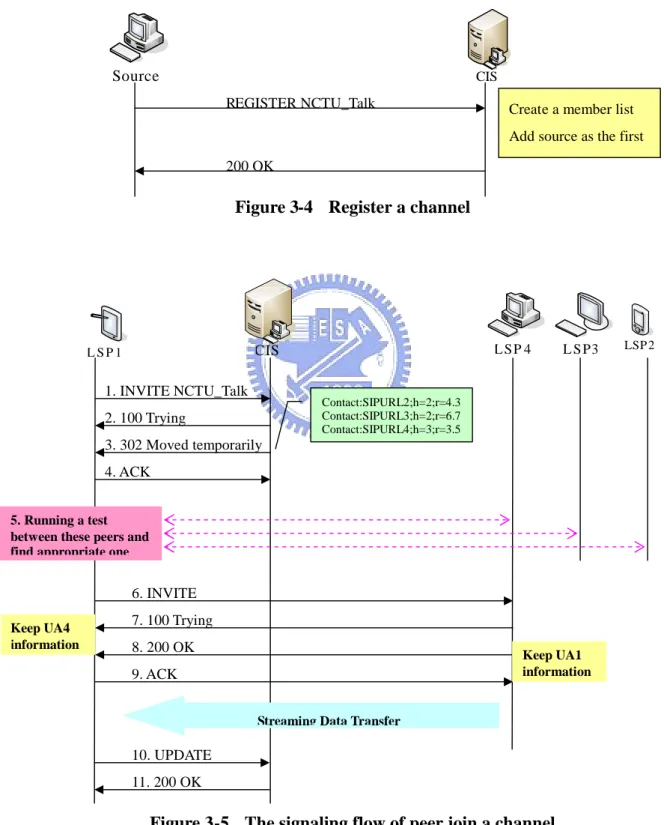
When a peer wants to share its live video streaming, it has to register the channel name to CIS. The CIS uses the user’s SIP URL and the channel name together as a unique identifier and creates a member list for it. Figure 3-4 shows the signaling flow of this method. Besides, the CIS should take charge of service announcement. Peers can send requests to the CIS to get a list of all channels registered. The first member of this channel must be the service provider itself.
The CIS receives this request and returns a member list to the new incoming peer. The peer chooses an existing member with the shortest routing path for relaying the streaming. Figure 3-5 illustrates the signaling flow when LSP1 gets the contact addresses of three members (LSP2~4) and their routing information.
Figure 3-4 Register a channel
Figure 3-5 The signaling flow of peer join a channel
Source CIS
Create a member list Add source as the first REGISTER NCTU_Talk 200 OK LSP 2 L S P 1 CIS L SP 4 L S P3 1. INVITE NCTU_Talk 3. 302 Moved temporarily 2. 100 Trying Contact:SIPURL2;h=2;r=4.3 Contact:SIPURL3;h=2;r=6.7 Contact:SIPURL4;h=3;r=3.5 5. Running a test between these peers and find appropriate one
4. ACK 6. INVITE 7. 100 Trying 8. 200 OK 9. ACK Keep UA1 information Keep UA4 information
Streaming Data Transfer
11. 200 OK 10. UPDATE
These members’information is packaged into a 302 Moved temporarily response to tell LSP1 that the CIS cannot serve it directly, but these peers could. LSP1 extracts the peers’ information from the response and inserts it into the member list. The contact list carried by response is formed as:
“Contact:sip:[email protected];h=[HopsToSource];r=[ RTT2Source]”
We want to find the best peer that has the shortest path from the source through the peer to LSP1, but a node close to the source provider may not close to LSP1. So LSP1 iteratively executes an ICMP ping-echo procedure for each contact URL to measure the number of hops and round trip delay between them. With the ICMP procedure, if the contact peers are reachable they copy the original data packets to a series of reply packets and send them back to the echo requesting nodes. Once the reply packets are received, LSP1 calculates the number of hops between and the round-trip time (RTT) by the difference from the first sending packet to the latest received one.
The ICMP echo function is implemented in every computer, so we can use this to measure the network latency. After the ICMP ping-echo procedure, we can obtain the “RTT2Peer” information of each peer. We have known the number of hops and the round trip delay from the peer to the source by parsing the SIP 302 response and we stored them into the “RTT2Source” of the peer data record. Therefore, by adding “RTT2Source” and “RTT2Peer”, LSP1 chooses the peer with the lowest transmission time to contact and save the results into two global variables with them. “G_HopsToSource” means the number of hops from the source through the parent node to it; and “G_RTT2Source” means the round-trip time.
1. G_HopsToSource = parent.HopsToSource + parent.HopsToPeer + 1 2. G_RTT2Source = parent.RTT2Source + parent.RTT2Peer
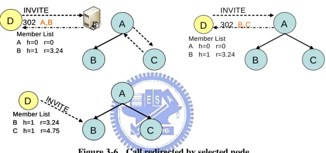
A C B D Member List B h=1 r=3.24 C h=1 r=4.75 INV ITE A C B A C B D Member List B h=1 r=3.24 C h=1 r=4.75 D Member List B h=1 r=3.24 C h=1 r=4.75 INV ITE A C B D Member List A h=0 r=0 B h=1 r=3.24 INVITE 302 B,C A C B D Member List A h=0 r=0 B h=1 r=3.24 INVITE 302 A,B A C B D Member List A h=0 r=0 B h=1 r=3.24 INVITE 302 A,B
be a parent node of the new one. When the disabled node receives an “INVITE” request, it sends another 302 response with its child nodes or a “404 Not found” back to the requesting node. The new incoming node adds the child record to its member list, delete the disabled node, choose another peer from the member list, and send an “INVITE” request until finding a parent node. After that, the new node should update the two measuring results to the CIS and will be asked to serve new other nodes who subscribe this channel later.
Figure 3-6 Call redirected by selected node
3.4
Node Disconnection
When a peer leaves, all of its children and their sub-tree need to be rearranged for receiving streaming media continuously. In general, each peer which wants to leave the channel must send a BYE request to its parent and children nodes. We call this a graceful departure. On the other hand, peer failure or network congestions lead to service disruption and we call this an ungraceful departure.
3.4.1
Graceful Departure
When a host leaves, it should notify the CIS and other nodes that have direct connections between them by sending a BYE request. Upon receiving the request, its parent node deletes the leaving peer from its member list and stops transferring streaming media. On the other hand, when its children receive a BYE request, the children first choose a new member from their member list respectively and rejoin to the overlay tree. There are two strategies to handle this event for their sub-trees. One is pretending that the departure event did not happen and transfer streaming media continuously for them. But the other, the child nodes who received BYE request will relay this request to their children recursively to the leaf nodes. All nodes in the sub-tree served by the leaving node have to rejoin the channel. Figure 3-7 shows the reconstruction procedures of the two strategies.
In our system, we use the first method that a child node does not relay the departing message for its parent. The main reason is that the second one makes the more changes for the overlaid tree. The change is not a bad thing for reconstructing the multicast tree, but during a node trying to rejoin the multicast tree the service is disabled. The reconstructing time of the first method is limited to a single node’s rejoining; in second method, the more nodes executing the rejoining procedure causes the more time to recover the service.
3.4.2
Ungraceful Departure
The fault tolerance problem is always a great challenge for internet service developer. We design a look-back mechanism by periodically exchanging messages based on Eric’s paper [15]. Once a peer is connected, it informs its parents of its presence by transmitting periodic“hello”messages. These messages are also used to propagate topology information,
such as the size of the sub-tree. Reception of a message generates an immediate response to confirm the parent’s presence. An Ungraceful departure occurs when a peer leaves the channel without notify its immediate nodes. When a host leaves, it stops forwarding video packets and is unresponsive to the “hello” probing. As time goes by, the probing node not receiving the echo from its parent detects the departure and starts up a reconstruction procedure. Besides, it replaces the leaving node and notifies the CIS to keep the accuracy of the member list on the CIS. A C A B C D F E E A C D F E F D 2.a 2.b 2.c A B C D F E A C D F E 1.a 1.b
Figure 3-7 1.a - 1.b The sub-tree is kept by a child node of the leaving node Figure 3-7 2.a – 2.c All nodes in the sub-tree will be notified recursively
3.5
Channel Switching Mechanism
As we mentioned before, more choices will encourage users to switch channels. This phenomenon has not been studied by other related works. In a bandwidth-limited environment, we should not transmit streaming data of different channels to a user at the same time. Especially there might be some embedded devices which could not handle two or more decoding jobs well. To solve this problem, we use the existing technique, cache, to reduce the response time when switching event occurs.
The data cached in every node is the member list that we have introduced in Section 3.1. These records are the reference when a host switches from one channel to another. In a direct thinking, channel switching is the combination of leaving and joining operations. The first step of joining procedure is to get some reference points from the CIS. Obviously, this is an overhead if the channel had been visited before. Besides, the node sends a BYE message to notify the CIS that it leaves from the origin channel and sends a UPDATE message after joining the target channel.
Our mechanism is to skip over the BYE message sent to the CIS, and use the stored member list replacing getting from the CIS, and send a UPDATE message when the client successfully switches to a target channel. Figure 3-8 compares the flows that use our channel switching mechanism. The doted lines are the eliminated messages by this mechanism. We reduce the number of total exchanging messages from 10 to 6.
Figure 3-8 Message flow of channel switching BYE 200 OK L e a v in g p a r t J o i n i n g p a r t BYE 200 OK INVITE 302 Moved Temporarily INVITE 200 OK UPDATE 200 OK
E
lim
in
a
te
d
p
a
rt
BYE 200 OK L e a v in g p a r t J o i n i n g p a r t BYE 200 OK INVITE 302 Moved Temporarily INVITE 200 OK UPDATE 200 OKE
lim
in
a
te
d
p
a
rt
Chapter 4
System Implementation
We implement the live video streaming sharing system on Microsoft Window XP operating system run on a PC. We use the integrated development environment - Microsoft Visual C++ 6.0 and the CCL SIP Protocol stack [] to meet our requirements. The SIP protocol stack is implemented by Computer & Communication Research Laboratories (CCL) of the Industrial Technology Research Institute (ITRI).
4.1
The Implementation of CIS
The CIS consists of three modules - channel manager, transaction manager, and SIP core. The channel manager manages the member lists for all channels registered by users. The channel manager adds, deletes, and updates the information of the member lists in a database. There are two tables maintained on the database. One is the channel list table which stores the channel identity and the SIP URL of the user who had registered a channel. The other is the peer table which stores the attributes listed in the Table 3-1.
The transaction manager controls the sate of each transaction created when the SIP core receives a SIP request. The transaction manager processes the request and generates a response for a transaction. And then a transaction enters into the WAIT_RETRANS state. When a response is sent by SIP core, the transaction goes to the TERMINATE state and destroyed by the transaction manager. The major part of CCL SIP protocol stack we modified is the parser of Contact header that enables a SIP request to contain the information of the member node.
The Figure 4-1 illustrates the flow chart of the CIS. When the SIP core receives a request from a LSP, it parses the request and creates the correct transaction. In the INVITE transaction, the channel manager checks the channel name and finds the member list of this channel. The records are sorted by “HopToSource” and “Usage” attributes. The channel manager picks M records to constitute a partial list. The value of M is determined as follows,
Figure 4-1 The processing flow chart of the CIS
list member the of size the is N 10, N log 5 10, N 2 10 N N M i n i t i a l R e c e i v e R e q u e s t I s I N V I T E ? C r e a t e a m e m b e r l i s t I s R E G I S T E R ? N o I s B Y E ? N o I s U P D A T E ? N o Y e s Y e s Y e s Y e s S o r t t h e M e m b e r l i s t N = s i z e o f m e m b e r l i s t K = N /2 i f N < 1 0 5 + L o g N i f N > = 1 0 M = 0 P i c k a n o d e w i t h m i n i m u m h o p s U s a g e + 1 M + 1 N o M o r e N o d e o r M > = K ? N o D e l e t e t h e r e c o r d f r o m m e m b e r l i s t R e t u r n 2 0 0 R e s p o n s e R e t u r n 3 0 2 R e s p o n s e a n d t h e p a r t i a l l i s t R e t u r n 4 0 0 R e s p o n s e Y e s I s U s a g e > = 1 0 Y e s A d d t h e r e c o r d i n t o t h e m e m b e r l i s t D e l e t e t h e n o d e f r o m t h e m e m b e r l i s t N o N o U p d a t e o r A d d t h e r e c o r d i n t o t h e m e m b e r l i s t
The partial list is sent with a “302 Moved temporarily” response. In a REGISTER transaction, the channel manager inserts a record into channel list table and adds the user into the member list. When the CIS receives a BYE request means the user wants to leave a channel which the user had subscribed, the channel manager deletes its record from the channel. Receiving a UPDATE request means the status of a user has changed and the channel manager should update the value of the attributes of a record or add a new record into the member list. Otherwise, if other type of requests received by the CIS, it sends back a 400 response.
4.2
The Implementation of LSP
Figure 4-2 shows the modules we use to implement the LSP. The architecture of the LSP is based on the CCL SIP UA []. The hollow block is the origins and the colored parts are modified with additional functionalities. The channel manager is designed for managing the member lists of the channels that a user had visited. A user can use the user interface to make commands to the call manager and the call manager calls the API of other modules to complete the commands.
We follow the call flow of the SIP standard but add the hops and round-trip time parameters for the references of our partial list selection algorithm. To send and understand these parameters, we modify the UA Core, sipTx, and SIP modules. When a session is initiated, the channel manager waits a period of time that decided by the parameter transferred by SIP message and sends a UPDATE request to inform the CIS that the LSP has joined the channel successfully and had enough bandwidth to relay streaming data for others.
video datagram. Each RTP session receives data from only one sending peer and sends to some receiving peers. In our system, a RTP link is a unidirectional link so each peer has only one relation in a session. The default type of the original RTP module is bidirectional, so we modify the cclRTP and RTP module to support unidirectional link and more receivers.
Figure 4-2 The structure of a LSP Call Manager Video Manager cclRTP Audio codec WavIO VideoLib Video codec Media Manager Channel Manager RTP SDP Manager UA Core SDP sipTx SIP Transport
CCL SIPUA module Modified module Our module
Call Manager Video Manager cclRTP Audio codec WavIO VideoLib Video codec Media Manager Channel Manager RTP SDP Manager UA Core SDP sipTx SIP Transport
Chapter 5 Conclusions
Multimedia and streaming sharing, such as personal TV show and personal radio station has been getting popular in recent years. Although this can be accomplished by a client-server model easily, the building cost is very expensive, especially the server’s computing power and network bandwidth for every user sharing a live streaming. In this thesis, we present an application layer multicast architecture based on a hybrid peer-to-peer model to share live video streaming. From the user’s view, peer-to-peer model provides a convenient solution for distributing and receiving live video streaming services, and the most important thing is that the services are free of charge. From the operator’s view, the CIS server only needs small bandwidth and computing power to organize the users to form a multicast tree for each streaming.
We also present a method to reduce the switching latency between multiple streaming services. A LSP stores the member lists for the visited channels. If the user wants to visit these channels, the information provides entry points of the channels where the LSP can contact directly. Using this mechanism, the LSP eliminates four steps from the original switching procedure.
In the future work, we will consider the scalability of the CIS. Although our live video sharing system organizes the users to construct application layer multicast trees to distribute their streaming. When the number of users increases, the CIS could be the bottleneck of whole system.
References
[1] R. Finlayson, “IP Multicast and Firewalls”, RFC 2588, May 1999 [2] ICECast. http://www.icecast.org
[3] Y.-H. Chu, S. G. Rao, S. Seshan, and H. Zhang, “A case for end system multicast,” in IEEE Jrnl. on Selected Areas in Communications (J-SAC), Sp. Issue on Network Support for Group Communication, 2003.
[4] ZHANG, X., LIU, J., LI, B., AND YUM, T.-S. P. “DONet/CoolStreaming: A Data-driven Overlay Network for Peer-to-Peer Live Media Streaming”. In IEEE INFOCOM (Mar. 2005), vol. 3, pp. 2102-2111.
[5] Miguel Castro , Peter Druschel , Anne-Marie Kermarrec , Animesh Nandi , Antony Rowstron , Atul Singh, “SplitStream: high-bandwidth multicast in cooperative
environments”, Proceedings of the nineteenth ACM symposium on Operating systems principles, October 19-22, 2003, Bolton Landing, NY, USA
[6] PeerCast P2P Broadcasting http://www.peercast.org
[7] Yatin Dilip Chawathe , Eric A. Brewer, “Scattercast: an architecture for internet broadcast distribution as an infrastructure service”, 2000
[8] Ion Stoica , Robert Morris , David Karger , M. Frans Kaashoek , Hari Balakrishnan, “Chord: A scalable peer-to-peer lookup service for internet applications”, Proceedings of the 2001 conference on Applications, technologies, architectures, and protocols for computer communications, p.149-160, August 2001, San Diego, California, United States
[9] J. Rosenberg, H. Schulzrinne, G. Camarillo, A. Johnston, J. Peterson, R. Spark, M. Handley, E. Schooler, “SIP: Session Initiation Protocol”, RFC 3261 June 2002 [10] B. Campbell, J. Rosenberg, H. Schulzrinne, C. Huitema, D. Gurle, “Session Initiation
Protocol (SIP) Extension for Instant Messaging” RFC 3428, December 2002
[11] M. Handley, V. Jacobson, “SDP: Session Description Protocol”, RFC 2327, April 1998 [12] M. Handley, V. Jacobson, C. Perkins, “SDP: Session Description Protocol”, RFC 4566,
July 2006
[13] H. Schulzrinne, S. Casner, R. Frederick, V. Jacobson, “RTP: A Transport Protocol for Real-Time Applications”, RFC 3550, July 2003.
[14] H. Schulzrinne, S. Casner, “RTP Profile for Audio and Video Conferences with Minimal Control”, RFC 3551, July 2003.
[15] E. Setton, J. Noh, and B. Girod, “Rate-Distortion optimized video peer-to-peer multicast streaming,” Workshop on Advances in Peer-to-Peer Multimedia Streaming at ACM Multimedia, pp. 39–48, Nov 2005