Short communication
Use of a fritless dual tapered column and a low flow interface
for capillary electrochromatography–mass spectrometry
Chao-Jung Chen, Chia-Hao Chang, Guor-Rong Her
∗Department of Chemistry, National Taiwan University, Taipei, Taiwan Available online 29 May 2007
Abstract
To avoid problems associated with the use of sintered frits to retain packing material, tapered columns were investigated for use with capillary electrochromatography–mass spectrometry (CEC-MS) analysis. Taking the advantage that negatively charged stationary phase particles have a net velocity directed towards the buffer reservoir (inlet) over a wide range in pH, a fritless CEC column with a single taper tip was prepared for CEC-MS analysis. During CEC-MS analysis, the tapered end was immersed in the buffer reservoir and the unmodified end was pointed toward the ionization source. For better sensitivity, this single tapered CEC column was coupled to ESI/MS using a low flow sheath liquid interface. With this setup, occasional blockage of the ESI sprayer by stationary phase particles was observed. In addition, significant dead volume was observed because the unmodified tip could not be inserted into the very end of the sprayer of the low flow sheath liquid interface. To circumvent these problems, a dual tapered CEC column was prepared. This fritless dual tapered column CEC-MS approach alleviated the problems of frit, sprayer blockage and extensive dead volume.
© 2007 Elsevier B.V. All rights reserved.
Keywords: Fritless capillary electrochromatography; Mass spectrometry; Dual tapered column; Low flow ESI interface; Triazines; Protein digestion
1. Introduction
The high separation efficiency and selectivity of capillary electrochromatography (CEC), when combined with the high specificity and sensitivity of mass spectrometry (MS) offers tremendous power for the analysis of complex mixtures. How-ever, one major obstacle in CEC related approaches is column fabrication. In a packed CEC column, frits are often used to retain stationary phase. By sintering the porous silica-based sorbents or silica gel, retaining frits are readily formed and fixed to the walls of a fused silica capillary. Unfortunately, frit fabrication is not highly reproducible leading to variation in column perfor-mance. In addition, capillaries are fragile at the position of the frit since the polyimide coating is removed during frit fabrication
[1]. Most importantly, because high temperature is used during the sintering of frits, the surface properties of the frits and the surface zeta potential of the packing material around the frit are different from the bulk packing material. This phenomenon is undesirable because the EOF difference across the frits has been proposed as one of the major causes of bubble formation in CEC
∗Corresponding author. Tel.: +886 2 33661648; fax: +886 2 23638058.
E-mail address:[email protected](G.-R. Her).
[2]. Bubble formation often makes the EOF unstable and may result in a breakdown in the CEC current. To alleviate bubble for-mation induced by sintered frits, several approaches have been proposed, including capillary pressurization[3,4], mobile phase degassing[5], use of low buffer concentration to limit the current
[6]and modification of frits with dimethyloctadecylchlorosilane
[7].
Alternatives to the use of sintered frits have generally focused on fritless CEC columns, such as open tubular (OT)[8–10]or monolithic CEC columns[11–13]. While no frit is needed in OT and monolithic CEC, sample capacity is limited in OT-CEC and trial and error optimization is often needed to select the proper composition for polymerization in monolithic CEC. Fur-thermore, although pore size can be controlled in monolithic CEC, a narrow distribution similar to that found with HPLC particles is difficult to obtain. To take the advantage of the large variety of commercial stationary phases available for HPLC, approaches to fabricate a fritless packed CEC column have been developed[14–19]. Horv´ath and co-workers developed a frit-less CEC column by sintering HPLC packing materials inside a capillary column[14]. However, particle sintering is a harsh treatment and regeneration of the stationary phase was needed. For packed CEC columns, Lord et al. have suggested that a tapered tip (∼10 m) instead of a sintered frit could be used
0021-9673/$ – see front matter © 2007 Elsevier B.V. All rights reserved. doi:10.1016/j.chroma.2007.05.069
to retain 3m particles during column packing because of the “keystone” effect. Consequently, a tapered CEC capillary with only one sintered frit (inlet) was fabricated and applied in CEC-MS using either a sheathless [20] or a sheath liquid interface[21]. Recently, a more robust internally tapered CEC column has been reported[22–24]. By slowing heating the end of a fused-silica column, the 75m i.d. × 375 m o.d. capil-lary could continuously self shrink to produce an internal taper of∼10 m i.d. × 375 m o.d. Despite the success, these meth-ods still employed an inlet frit and thus the issues cited earlier with respect to the use of frits were not completely elimi-nated.
Recently, Baltussen and van Dedem[25]described the use of a 50m i.d. capillary as a retaining column to keep par-ticles within a 100m i.d. CEC column. The 100 m i.d. CEC column was connected to a 50m i.d. capillary through a peek union. In practice, the two capillaries have to be cut extremely flat and precisely assembled in a PEEK union to ensure that the particles will be retained inside the 100m i.d. capillary.
Because the silanol group of ODS packing material may dissociate to negative Si–O− over a broad pH range, they are negatively charged and are attracted toward the inlet reservoir instead of MS ionization source. Consequently, under certain conditions, an outlet frit may not be needed[26,27]. Based on this assumption, Bruin and co-workers[27]proposed a fritless CEC-UV approach by tapering only one end of a CEC column. The tapered end acted as a particle retaining frit during column packing and as an inlet frit in CEC operation. Using the same concept, Ceriotti et al. [28] fabricated a single tapered chan-nel in chip-CEC-UV analysis. The possibility of using a similar approach in CEC-MS was investigated in this laboratory. Ini-tially, a separation column with a single tapered end was coupled to MS using a low flow ESI interface. A low flow interface was selected because of its superior ESI sensitivity than a conven-tional sheath liquid interface[29]. However, limitations were observed in the single tapered CEC column approach. To over-come the obstacles encountered, a dual tapered CEC column was prepared. The potential and limitations of using either a single or a dual tapered packed CEC column format for CEC-MS are explored.
2. Experimental 2.1. Chemicals
Simazine, atrazine, propazine, ametryn, prometryn, ter-butryne, prometon and simetryn were obtained from Supelco (Bellefonte, PA). Ammonium acetate, methanol, acetonitrile and acetic acid, were purchased from J.T. Baker (Phillipsburg, NJ) and used without further purification. Deionized water (Milli-Q Water System, Millipore Inc., Bedford, MA) was used for the preparation of the samples and buffer solutions. Myoglobin (equine heart), trypsine and ammonium bicarbonate were pur-chased from Sigma–Aldrich Chemical Co. (St. Louis, MO, USA). The ODS particles (5m, 100- ˚A pore size) were pur-chased from Macherey-Nagel (D¨uren, Germany).
2.2. In solution digestion
Myoglobin (1 mg) was dissolved in 1 mL 50 mM ammonium bicarbonate and was thermally denatured by incubation at 90◦C for 20 min [30]. The sample was then cooled to 37◦C before trypsin was added to initiate the digestion process. The ther-mally denatured protein solution was enzymatically digested with trypsin at 37◦C for 6–8 h. The concentration of trypsin was maintained at 40:1 (wt of substrate/wt of trypsin).
2.3. Preparation of a tapered capillary packed column
To prepare a tapered tip dimension of 25m o.d. × 15 m i.d., a capillary with 50m i.d., 375 m o.d. (Polymicro Tech-nologies, Phoenix, AZ) was drawn manually using a vertically suspended section of capillary to which a small weight (45 g) had been attached. The capillary was slowly heated to the melting stage using a butane/oxygen micro-torch (Pro-Iroda Industries Inc., Taiwan) and then quickly withdrawn. A tip of∼15 m i.d. and 25m o.d. was obtained by removing the end of the tip using a ceramic cutter aided by visual inspection with a microscope.
The tapered capillary column (∼40 cm) was then mounted on a homemade pressure vessel that served as a packing reser-voir. A slurry of 5 mg/mL 5m ODS in methanol was sonicated for 20 min to prevent aggregation of particles and subsequently transferred into the reservoir. The pressure vessel was connected to a nitrogen cylinder. Under high pressure nitrogen (1500 psi), the particles were packed into the capillary and retained in the column. After packing, the single tapered CEC column was ready for use in single tapered CEC-MS approach. In the fab-rication of a dual tapered CEC column, the unmodified end (375m o.d.) of a single tapered CEC column was drawn man-ually using the same method as described in the fabrication of a single tapered CEC column. The newly tapered outlet end was cut to have a dimension of ∼5 m i.d. × 10 m o.d. using a ceramic cutter aided by visual inspection with a microscope. A LC pump was used to condition CEC columns for 20 min before CEC-MS experiments.
2.4. The fabrication of a low flow interface
The low flow interface was fabricated using the method described by Chen et al. [29]. Briefly, a 2.5 cm× 450 m i.d.× 1.2 mm o.d. fused-silica capillary (Polymicro Technolo-gies, Phoenix, AZ) with a tapered tip of ∼25 m orifice was fabricated. The tip was inserted into a liquid reservoir (a micro centrifuge tube with a drilled hole) and used as the sprayer for ESI. In CEC-MS operation, the makeup liquid was injected into the reservoir using a 500L syringe. Electrical contact was achieved by inserting a platinum (Pt) wire (∼ 400 m diam-eter) into the liquid reservoir. On average, the makeup solution (70% MeOH, 1% acetic acid) was resupplied every 10 runs.
2.5. CEC instrument
The CEC instrument was configured in-house. Briefly, the setup consisted of a CZE1000R high-voltage power supply
(Spellman, Plainview, NY) connected to a platinum electrode in a vial containing a running buffer and operated at constant-voltage mode. The inlet end of the separation capillary was placed in the CEC buffer reservoir, and the outlet end was inserted into a low flow interface.
2.6. Mass spectrometer
All mass spectrometry experiments were conducted on a LCQ ion-trap mass spectrometer (Finnigan MAT, San Jose, CA). In the analysis of triazines, the mass spectrometer was scanned from m/z 150 to m/z 400. For tryptic peptides detection, the mass spectrometer was scanned over a mass (m/z) range of 400–1800, followed by a product scan of the most abundant peak, using a collision energy setting of 35%. System control and data col-lection were performed using Xcalibur software (version 1.2). A commercial x–y–z translation stage for the LCQ nanospray source (Protana Co., Odense, Denmark) was used for mounting the low flow sheath liquid CEC-MS interface. The position of the interface could be adjusted via the micrometer screws of the translation stage. A nebulizing gas was not necessary because of the lower flow rate (∼ 400 nL/min) of the low flow ESI interface. The heated capillary was kept at a temperature of 250◦C.
3. Results and discussion
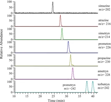
To avoid the use of frits in a packed CEC column, and to pre-vent particles flowing out of the column, a column with a tapered tip was prepared (Fig. 1a). In the CEC-MS setup (Fig. 2a), the tapered tip was immersed in the buffer reservoir and the unmod-ified end was inserted into a low flow ESI interface. To evaluate the performance of the single tapered CEC-MS approach, a mix-ture of eight triazines (20 ppm each) was analyzed using a single tapered column. The optimized separation condition[21]was used in the analysis of the eight-triazine mixture. This prelimi-nary result (Fig. 3) proves that a column with a single tapered tip is feasible for CEC-MS analysis. Unfortunately, after about half a dozen runs, particles were found in the sprayer of the low flow interface. These particles occasionally blocked the sprayer and terminated the ESI signal. This observation suggested that
Fig. 1. Schematic representation of (a) a single tapered CEC column and (b) a dual tapered CEC column.
Fig. 2. Schematic representation of (a) a single tapered CEC column inserted into a low flow interface and (b) a dual tapered CEC column inserted into a low flow interface.
packing material near the outlet exit might be flushed out of the column. This observation was also reported by other groups in CEC-UV studies [27,28]. To alleviate this problem, Bruin and co-workers[27]has proposed an approach involving coat-ing the inner wall with polyvinyl alcohol (PVA) to reduce EOF
Fig. 3. Mass electrochromatograms of the analysis of a 20 ppm eight-triazine mixture by CEC-MS using a single tapered column. Conditions: Mobile phase, 70% (v/v) ACN containing 20 mM ammonium acetate, pH 7.0. Column: 34 cm, packed to 31 cm with 5m ODS particles. The voltage applied to the buffer vial was 21 kV. The ESI voltage was set at 2 kV. The small shoulder peak at the m/z trace could be attributed to the34S isotope of ametryn (m/z 228).
Fig. 4. Mass electrochromatograms of the analysis of a 20 ppm eight-triazine mixture by CEC-MS using a dual tapered column. Conditions: Mobile phase, 70% (v/v) ACN containing 20 mM ammonium acetate, pH 7.0. Column: 32.5 cm, packed to 31 cm with 5m ODS particles. The voltage applied to the buffer vial was 21 kV. The ESI voltage was set at 2 kV.
in single tapered CEC-UV. This method reduced, but did not completely eliminate the problem of unintended migration of packing material.
In addition to unintended migration of stationary phase parti-cles out of the column, excessive dead volume is created because an un-tapered tip (375m o.d., 50 m i.d.) cannot be fully inserted into the tip of the low flow ESI sprayer. For a low flow sprayer, to achieve optimal sensitivity, the tip was tapered from 450m i.d. × 1.2 mm o.d. to an orifice of ∼25 m (Fig. 2a). To overcome these problems, the outlet end of the column was also tapered. Without the “keystone” effect, to retain the 5m ODS particles, a size of∼5 m i.d. was chosen for the outlet. The ∼5 m i.d./10 m o.d. tip (Fig. 1b) allowed the CEC column to be readily inserted into the ESI sprayer as shown inFig. 2b. Given that the column i.d. was reduced from 50 to∼5 m at the outlet, one would wonder the effect of the small ID on CEC operation. Fortunately, CE-UV analysis indicated no significant difference in both elution time and peak resolution (data not shown).
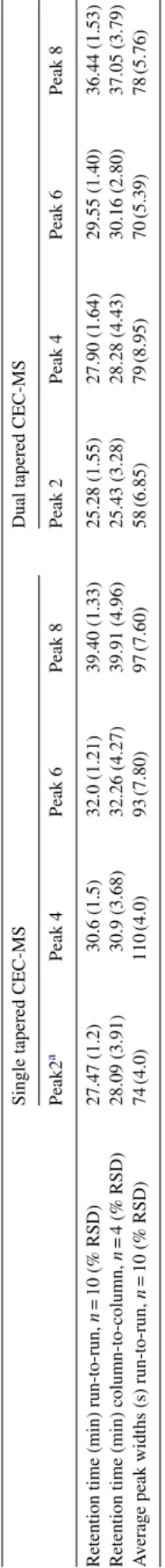
The performance of the dual tapered column in terms of retaining packing particles and reducing dead volume in CEC-MS was evaluated by analyzing the same triazine mixture (Fig. 4). After more than 10 runs with the dual tapered CEC-MS, no particles were observed in the ESI sprayer. Mainly because of smaller dead volume between the column and the low flow sprayer, the peak widths (Table 1) from the dual tapered CEC-MS were found to be slightly narrower than the peaks observed in the single tapered CEC-MS.
Although there is no polyimide coating at both ends of the dual tapered CEC column, the tapered ends were not very fragile
and could endure a slight collision. A dual tapered CEC column Table
1 Peak widths and RSDs of retention time from run-to-run and column-to-column for single and dual tapered CEC columns Single tapered CEC-MS Dual tapered CEC-MS Peak2 a Peak 4 Peak 6 Peak 8 Peak 2 Peak 4 Peak 6 Peak 8 Retention time (min) run-to-run, n = 1 0 (% RSD) 27.47 (1.2) 30.6 (1.5) 32.0 (1.21) 39.40 (1.33) 25.28 (1.55) 27.90 (1.64) 29.55 (1.40) 36.44 (1.53) Retention time (min) column-to-column, n = 4 (% RSD) 28.09 (3.91) 30.9 (3.68) 32.26 (4.27) 39.91 (4.96) 25.43 (3.28) 28.28 (4.43) 30.16 (2.80) 37.05 (3.79) A v erage peak widths (s) run-to-run, n = 1 0 (% RSD) 74 (4.0) 110 (4.0) 93 (7.80) 97 (7.60) 58 (6.85) 79 (8.95) 70 (5.39) 78 (5.76) aPeak 2, atrazine; peak 4, prometon; peak 6, ametryn; peak 8, terb utryn.
could perform dozens of runs without any damage. Although an internally tapered CEC column is more robust, the outer diam-eter (∼375 m) of the tip is significantly larger than that of an externally tapered column which could cause significant dead volume as in a single tapered CEC column.
Because of the use of a flame in fabricating the outlet taper, it is difficult to make a tapered tip without a dead volume between the tip and the packing material. Typically, there is a 1–2 cm empty space between the tapered end and the packing material (Fig. 1b). The empty space is not expected to affect resolution to a significant extent because, unlike the eluent between column and the low flow sprayer, the eluent in this empty space is driven by EOF and has a minimal mixing effect. The slightly narrower peaks from dual tapered columns than that of single tapered columns (Table 1) are consistent with the speculated minimal mixing effect.
Because of the empty space, occasionally some particles were found to migrate towards the outlet end of the column during CEC-MS operation. Fortunately, this phenomenon did not result in a significant effect as the RSDs of retention time from run-to-run were found to be less than 1.64% (n = 10) (Table 1). The RSDs of retention time from column-to-column for both single tapered and dual tapered column are shown in Table 1. The slightly higher RSDs of column-to-column than that of run-to-run could be attributed to the fact that it is not easy to have the same packing length in all tapered CEC columns.
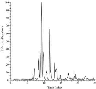
The analysis of a complex peptide mixture is a challenging analytical task which becomes increasing important in the recent development of life science. In the analysis of tryptic digests from myoglobin (∼50 M) using a dual tapered column, the peptide mixture was electrokinetically injected into the capillary at 10 kV for 8 s. The mixture was analyzed using a mobile phase
Fig. 5. The base peak electrochromatogram of tryptic perptides from myoglobin (50M) using a dual tapered column. Conditions: Mobile phase, 60% (v/v) ACN containing 20 mM ammonium acetate, pH 4.0. Column: 32.5 cm, packed to 31 cm with 5m ODS particles. The voltage applied to the buffer vial was 21 kV. The ESI voltage was set at 2 kV.
of pH 4.0, 60% ACN, 20 mM ammonium acetate. As shown inFig. 5, the tryptic peptides were separated within 25 min. Data-dependent MS/MS analysis followed by a Mascot search of the NCBInr database gave a sequence coverage of 81% and a Mascot score of 600 (p < 0.05). The result demonstrates that the dual tapered CEC-MS approach has the potential to be used in the analysis of tryptic peptides for protein identification.
4. Conclusion
Based on a dual tapered CEC column and a low flow interface, a simple method for CEC-MS was developed. By using tapered tips instead of sintered frits, the problems caused by sintered frits were avoided (e.g. bubble formation, peak distortion, etc.) and the dead volume between the separation column and the low flow sprayer was greatly reduced. Because of its easiness of fabrication, small dead volume, without the problem of bubble formation during operation, and high reproducibility in run-to-run and column-to-column analysis, a dual tapered CEC column provides an attractive alternative for CEC-MS applications.
Acknowledgment
This work was supported by the National Research Council of the Republic of China.
References
[1] S.E. van den Bosch, S. Heemstra, J.C. Kraak, H. Poppe, J. Chromatogr. A 755 (1996) 165.
[2] H. Poppe, J. Chromatogr. A 778 (1997) 3.
[3] J.-L. Liao, N. Chen, C. Erickson, S. Hjerten, Anal. Chem. 68 (1996) 3468.
[4] R.M. Seifar, W.Th. Kok, J.C. Kraak, H. Poppe, Chromatographia 46 (1997) 131.
[5] H. Rebscher, U. Pyell, Chromatographia 38 (1994) 737.
[6] R.J. Boughtflower, T. Underwood, C.J. Paterson, Chromatographia 40 (1995) 329.
[7] R.A. Carney, M.M. Robson, K.D. Bartle, P. Myers, J. High Resol. Chro-matogr. 22 (1999) 29.
[8] N.Y. Han, J.T. Hautala, T. Bo, S.K. Wiedmer, M.L. Riekkola, Electrophore-sis 27 (2006) 1502.
[9] J.L. Chen, Electrophoresis 27 (2006) 729.
[10] J.J. Pesek, M.T. Matyska, G.B. Dawson, J.I. Chen, R.I. Boysen, M.T.W. Hearn, Anal. Chem. 76 (2004) 23.
[11] F. Chuzo, J. High Resol. Chromatogr. 23 (2000) 89.
[12] S.M. Ngola, Y. Fintschenko, W.Y. Choi, T.J. Shepodd, Anal. Chem. 73 (2001) 849.
[13] Y. Li, R. Xiang, C. Horvath, J.A. Wilkins, Electrophoresis 25 (2004) 545. [14] R. Asiaie, X. Huang, D. Farnan, C. Horv´ath, J. Chromatogr. A 806 (1998)
251.
[15] M.T. Dulay, R.P. Kulkarni, R.N. Zare, Anal. Chem. 70 (1998) 5103. [16] C.K. Ratnayake, C.S. Oh, M.P. Henry, J. High Resolut. Chromatogr. 23
(2000) 81.
[17] Q. Tang, N. Wu, M.L. Lee, J. Microcolumn Sep. 11 (1999) 550. [18] G. Chirica, V.T. Remcho, Electrophoresis 20 (1999) 50. [19] G. Chirica, V.T. Remcho, Electrophoresis 21 (2000) 3093.
[20] G.A. Lord, D.B. Gordon, P. Myers, B.W. King, J. Chromatogr. A 768 (1997) 9.
[21] C.H. Chang, C.J. Chen, Y.C. Chuang, G.R. Her, Electrophoresis 27 (2006) 4303.
[23] D. Norton, J. Zheng, N.D. Danielson, S.A. Shamsi, Anal. Chem. 77 (2005) 6874.
[24] J. Zheng, S.A. Shamsi, Electrophoresis 27 (2006) 2139.
[25] E. Baltussen, G.W.K. van Dedem, Electrophoresis 23 (2002) 1224. [26] G.A. Lord, D.B. Gordon, L.W. Tetler, C.M. Carr, J. Chromatogr. A 700
(1995) 27.
[27] M. Mayer, E. Rapp, C. Marck, G.J.M. Bruin, Electrophoresis 20 (1999) 43.
[28] L. Ceriotti, N.F. de Rooij, E. Verpoorte, Anal. Chem. 74 (2002) 639. [29] Y.R. Chen, M.C. Tseng, Y.Z. Chang, G.R. Her, Anal. Chem. 75 (2003)
503.