Determination of Heat of Transformation
in a Cold-Rolled Martensitic TiNi Alloy
H.C. LIN and S.K. W U
W e studied the heat o f transformation, AH, in martensitic transformations in a cold-rolled equiatomic TiNi alloy with differential scanning calorimetry (DSC), X - r a y diffraction (XRD), and microhardness measurements. Results o f our experiment indicate that the martensite sta-bilization and stress-induced parent (SIP) B2 phase are introduced when the TiNi martensite is cold rolled at room temperature. The SIP formation seems to be related to the lattice softening phenomenon occurring in the martensite, while the A H v a l u e o f the f i r s t reverse martensitic transformation decreases enormously for the cold-rolled equiatomic TiNi alloy. W e are pro-posing possible explanations for these results: (1) the occurrence o f SIP, w h i c h reduces the transformable martensite volume; (2) the release o f accumulated elastic energy induced by the cold rolling; and (3) the recovery o f defects induced by cold rolling and release o f the heat o f recovery. W e also found that the retained dislocations can depress the martensitic transformation temperatures and induce the R-phase transformation a f t e r the occurrence o f the first reverse martensitic transformation.
I. I N T R O D U C T I O N
A M O N G many shape memory alloys, TiNi alloys are the most popular because they can be deformed in a duc-tile manner to more than 50 pct strain p r i o r to fracture and show the shape memory effect o r pseudoelasticity (PE) over a wide range o f strain up to 8 pctJ II The trans-formation behavior and mechanical properties in TiNi binary alloys [2-6J and TiNiX ternary alloys t7-1°j have been studied extensively. These studies have confirmed that transformation behaviors and mechanical properties can be affected by internal stresses induced by many thermal-mechanical treatments, including t h e r m a l cycling, t~,12] aging treatment in Ni-rich alloys, t13-~61 and annealing im-mediately following cold working. [~7,~8]
Many recent articles have reported deformation be-havior and stress effects in TiNi alloys07,18,2°,2tj and stated that the stress in these alloys significantly affects the start and finish transformation temperatures and induces the R-phase transformation and that the microstructure with dislocations o r precipitates impedes the movement o f martensite interfaces and depresses the Ms point. All o f these reported studies, however, were conducted on TiNi specimens w h i c h had been deformed with subsequent annealing. TiNi specimens that have been deformed but not annealed are seldom studied, although some results have been implied in the r e p o r t s . [22,23,241 In our previous article, [wl w e discussed the effects o f cold rolling on the martensitic transformation o f equiatomic TiNi alloy pri-marily through transmission electron microscope ( T E M ) observation and internal friction measurement. W e ob-served the phenomenon o f martensite stabilization in the cold-rolled TisoNis0 alloy at r o o m temperature. W e ex-pected the deformed structures, such as distorted mar-tensite and dislocations/vacancies, to i m p e d e the reverse
H.C. LIN, f<~rmedy Graduate Student, Institute of Materials Science and Engineering, National Taiwan University, is Assistant Professor, Department of Materials Science, Feng Chia University, Taichung, Taiwan, Republic of China. S.K. WU, Professor, is with the Institute of Materials Science and Engineering, National Taiwan University, Taipei, Taiwan 106, Republic of China.
Manuscript submitted April 2 0 , 1992.
martensitic transformation by imposing a frictional stress on the martensite/martensite and martensite/parent interfaces. This would cause the reverse martensitic transformation temperatures to shift to higher values, since the transformation would require additional driving force to overcome the frictional stress. In this study, we plastic-deformed the equiatomic TiNi alloy by cold rolling at room temperature and then conducted differential scan-ning calorimetry (DSC), X - r a y diffraction (XRD), and microhardness measurements. In the following sections, we systematically describe the transformation heat ex-hibited in this deformed TiNi a l l o y and its relation to the degree o f cold roiling.
II. E X P E R I M E N T A L P R O C E D U R E W e used the conventional tungsten arc melting tech-nique to prepare the equiatomic TiNi alloy. T i t a n i u m (purity, 99.7 pct) and n i c k e l (purity, 99.9 p e t ) , totalling about 60 g , were m e l t e d and remelted at least six times in an argon atmosphere. Pure titanium buttons were also melted and used as a getter. The mass loss during melt-ing was negligible. The as-melted button was homoge-n i z e d at 1050 °C f o r 72 hours ahomoge-nd quehomoge-nched ihomoge-n w a t e r , then hot-rolled to a plate o f 3-ram thickness. Specimens f o r cold rolling were carefully cut f r o m the plate with a low-speed diamond saw. These specimens were then an-nealed at 800 °C for 2 hours and cooled in a v a c u u m furnace. After annealing, some specimens were cold-rolled at r o o m temperature to a 5, 10, 20, and 40 pct reduction in thickness and then subjected to the DSC, XRD, and microhardness measurements. The temperature increase in the specimens during the cold-rolling process was very slight, even in the 40 pct thickness-reduced specimen.
A Du Pont 9990 t h e r m a l analyzer equipped with a quantitative scanning system 910 DSC cell was used to run controlled heating and cooling on samples encap-sulated in an a l u m i n u m pan. Temperatures ranged f r o m - 6 0 °C to +300 °C with a heating/cooling r a t e o f 10 °C/min. The heat o f transformation, AH, was au-tomatically calculated f r o m the area under the DSC peak
with the equipment software packages. The XRD anal-ysis was carried out at room temperature with the PHILIPS* PW1710 X-ray d i f f r a c t , m e t e r under the
con-*PHILIPS is a trademark of Philips Electronic Instruments Corporation, M a h w a h , NJ.
ditions o f CuKcz radiation, 30 kV tube voltage, and 20 mA current. The specimen size for XRD was 20 by 20 mm. Specimens for the hardness testing were m e -chanically polished and then measured in the Vickers microhardness tester with a 1000-g load at room tem-perature. F o r each specimen, the hardness value, H v ,
was averaged from at least five test readings.
l I I . EXPERIMENTAL R E S U L T S A . DSC Measurement on the Cold-Rolled Specimens
Figure 1 shows the DSC curves for the 5 pct cold-rolled TisoNs0 specimen in the first heating cycle and subsequent cooling and heating cycles. Compared with the experimental results o f the internal friction testing ug]
and electrical resistance measurements,tzS~ the DSC peaks shown in Figure 1 are associated with the martensitic transformation o f B2 ~ B 19' (B2: parent phase, CsCI-type structure; B 19': martensite, monoclinic distortion o f the B19 structure). The first heating curve shows an endothermic reaction, with A H being 16.55 J / g and the peak temperature A* near 101.9 °C. The cooling curve, however, shows an exothermic reaction, with A H being 24.16 J / g and the peak temperature M * near 37.9 °C. In the second heating curve, A* appears at 75.7 °C, with
A H = 24.57 J / g .
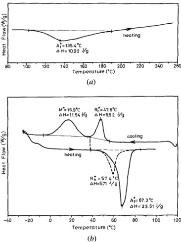
Figures 2(a) and (b) show the DSC curves o f the first heating cycle and subsequent cooling and heating cycles, respectively, for the 20 pct cold-rolled specimen. In Figure 2(a), peak A* appears at 135.4 °C. In Figure 2(b), there are two separate peaks on the cooling run; one is associated with the martensitic transformation, M* = 16.9 °C, and the other is associated with the R-phase transformation, R* = 47.6 °C (R phase: intermediate
_,o
Lt. "1-M * = 3 7 9 " C Z~ H=24:1 6 J / g h e a t i n g 2b ~b cooling 60 8'0 i()0 120 140 T e m p e r a t u r e (*C)Fig. 1--DSC curves for the as-annealed Tis0Nis0 alloy.
phase, rhombohedral structure). However, on the fol-l o w i n g heating run, onfol-ly an endothermic peak A* ap-pears at 67.3 °C. If cooling is stopped at 37 °C (between M * and R~ temperatures) and then resumed, another peak R* appears before the A* peak at about 57.4 °C (shown as the dashed line in Figure 2(b)). This implies that the martensite phase is more stable than the R phase before transforming to B2 phase during the heating cycle. Figure 2(b) indicates that the transformation sequence o f the 20 pct cold-rolled specimen is B2 ~ R ~ B19' on cooling and B 19' ~ B2 on heating.
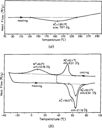
Figures 3(a) and (b) show the same curves as Figures 2(a) and (b), this time for the 40 pct cold-rolled specimen. In Figure 3(b), there are also two separate peaks on the cooling run, M* = 8.0 °C, R* = 52.1 °C. On the heating run, there is a d u p l e x peak contributed by both the martensitic and R-phase transformations. When the measurement on the cooling run is stopped at 37 °C (between M* and R*) and again resumed, the peak R* appears after the peak A* at about 63.3 °C (shown as the dashed line in Figure 3(b)). This means that B 19' --~ R transformation occurs before R --~ B2 trans-formation. The DSC curves f o r both the as-annealed and 10 pct cold-rolled specimens are similar to those shown in Figure 1, except for the difference o f peak tempera-tures and A H values, and, hence, are omitted here. All experimental results, including peak temperatures and AH values, are summarized in Table I. The data in Table I are also plotted in Figures 4 and 5 for A* and
o
J h e o t i n g A I = 135.4 C
z~ H = 10.92 J / g
16o " iko i ~ . o " ' i ~ o ' i ~ o ' 260 ' 2 ~ o " 2/,o '
T e m p e r o t u r e ( ° C )
(a)
M*__ 16,9Oc Q c = 4 7 . 6 C~' . 5.52 J / g ~ H = 11.54 J,,/g ,",,X,'
/
= _ ' , ' \ /- 4 o ' J , o ' 6 ' 2'o ' ~;o ' 6'o " o b ' ~ o 12o T e m p e r o t u r e (*C)
( b )
Fig. 2 - - D S C curves for the 2 0 pct cold-rolled Ti~0Nis0 alloy: (a) the first heating run and (b) the following cooling and heating runs.
E~ o m LL 7o' 9'o heating I A~=195.1°C txH= 7.97 J/g ' d o ' ~ 0 ' 1 ~ 0 ' ~÷0 ' 1 ~ 0 ' 2 ~ 0 ' 2 ~ 0 ' 2 ~ 0 ' 2 ~ 0 ' 2 ~ 0 Temperature (*C) (a) R~=52 1*C M*=8.0,C Z~H= 6.il J/g ~ cooling A~= 59.0"c~J ,',H=21.19 J//g -40 4 0 6 2'0 do 6b do 10o Temperature (*C)
(b)
Fig. 3--DSC curves forthe 40 pct cold-rolled Ti~0Nis0 alloy: (a) the
first heating run and (b) the following cooling and heating runs.
AH(A*) vs thickness reduction and for M * , A * , R*, R *
vs thickness reduction, respectively. The characteristics
shown in Figures 4 and 5 will be discussed in Section IV.
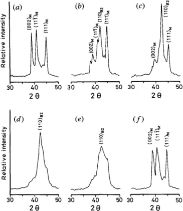
B . XRD Measurement o f Cold-Rolled Specimens Figures 6(a) through (f) show XRD patterns of cold-rolled equiatomic TiNi alloy with various thickness re-ductions. The typical XRD spectra for as-annealed TiNi martensite are shown in Figure 6(a). After cold rolling, as shown in Figures 6(b) through (e), the line intensity of martensite spectra decreases; but the parent B2 p h a s e appears and reaches the m a x i m u m value at 10 pct degree of cold rolling, then recedes and broadens at 20 and
40 pct of cold rolling. If the cold-rolled specimens are subjected to a reverse martensitic transformation, the diffraction peak of the B2 p h a s e disappears and the dif-fraction spectra recover to the martensite spectra, as shown in Figure 6(f), which is similar t o Figure 6(a). We will discuss these interesting characteristics in Section IV.
C. Hardness Test o f Cold-Rolled Specimens
Figure 7 shows the hardness (Hv) v sthickness
reduc-tion for the cold-rolled equiatomic TiNi alloy at room temperature. In Figure 7, curve A is the hardness of the as-cold-rolled specimens; curve B is the hardness of the same specimens subjected to a reverse martensitic
trans-formation of B19' ~ B2 and then t o a forward
mar-tensitic transformation of B2 ~ B 19'. In Figure 7, b o t h curves A and B increase w i t h increasing degree of thick-ness reduction, but the hardthick-ness of curve B is always lower than that of curve A, especially when the thickness reduction is more than 5 pct. The features appearing in Figure 7 will also be discussed in Section IV.
IV. D I S C U S S I O N
A . Martensite Stabilization and Stress-Induced Parent Phase (SIP) in the Cold-Rolled Equiatomic TiNi Alloy We studied the cold-rolled equiatomic TiNi alloy by TEM observation in our previous article,t~9J That study revealed a variety of deformed martensite morphologies. In addition to t h o s e deformed morphologies, though, other deformed features are induced during cold rolling, such as dislocations and vacancies. Due t o the complex mor-phologies existing in the deformed martensite, however, dislocations and vacancies are shielded and not easily detected by TEM. As mentioned in the Introduction, these
deformed structures seem to be related to the martensite
stabilization. 1191 Differential scanning calorimetry
mea-surements also indicate the martensite stabilization, as
shown in Figure 4, where the reverse martensitic trans-formation temperature A* shifts t o a higher value with increasing degree of cold rolling. After the occurrence of the first reverse martensitic transformation of B 19' --~ B2, the characteristic of martensite stabilization d i s a p -pears, as indicated by the M * and A* temperatures in
Table I. Peak Temperature and A H Values o f A*, A*, M*, R*, and R* at Various Degrees o f Cold Rolling
Cold Rolling 0 Pct 5 Pct 10 Pct 20 Pct 40 Pct A* (°C) 86.1 101.9 117.6 135.4 195.1 AH ( J / g ) 25.16 16.55 13.40 10.92 7.97 A* (°C) 86.1 75.7 72.3 67.3 59.0 AH (J/g) 25.16 24.57 24.01 27 51 -M* (°C) 45.8 37.9 29.7 16.9 8.0 AH ( J / g ) 23.98 24.16 22.73 11.54 10.76 R* (°C) - - - - 37.4* 47.6 52.1 AH ( J / g ) - - - 5.52 6.21 R* (°C) - - - 57.4 63.3 AH (J/g) - - - 5.71 6.50
13. E F -< 2 2 0 ' 1 90 160" 130 100 o : A~ Temperature , _ ~ z~ : zxH value / -25 .21
-e
-17---"4
13 - r <3 9 70 ,5 0 5 10 2 0 30 40 Cold Rolling (%)Fig. 4 - - T h e A* temperature and A H ( A * )valuevsthe degree of cold rolling for the TisoNis0 alloy.
60 (a)
I
.~ B2 phase , - - a ~ , E 40-'. I~ " ' ~ a R-phase * ~ zz -~ 20. " o , Martensite o I ~ (b) "E~80- ~ B2 phase I--- ° ~ o . . " o 60- . _ -,- o.'"R'~
El , ~ M ortensite 4 0 . I , , , 0 10 20 30 40 C o l d Roiling (%)Fig. 5 - (a) M* and R* temperatures and (b) A* and R * temperatures
v s the degree of cold-rolling for the TisoNis0 alloy.
~ g ~ m
t
Table I. Although the martensite stabilization d i s a p
-pears, the deformation-induced dislocations remain in the
deformed specimens and affect their subsequent
trans-formation behaviors. The M * and A* temperatures
de-crease, then, with increasing degree of cold rolling. The hardness test results shown in Figure 7 also support this conclusion: curves B and A show the hardness of the deformed martensite with and without the first reverse
martensitic transformation of B19' ~ B2, respectively.
There are plenty of dislocations retained in the
martens-ite of curve B. The hardness difference between
curves A and B comes from the disappearance of de-formed structures and the annihilation of vacancies in the
12 .=_
g:
(a) z gE. w ao ' 4'o sb 2 0 (b) ~ (c) g ~ ab ' 4'o 5b ab & 2 0 2 0 z<
sb (d) ~ s .~_ oe a0 & ~b 2 0 (e) ( f ) x ~ 3'0 4'0 50 30 40 50 2 e 2 eFig. 6--The XRD spectra for the cold-rolled TisoNi5o alloy: (a) as-annealed, (b) 5 pct, (c) 10 pct, (d) 20 pct, (e) 40 pct, and (f) specimen(d) subjectedto a reverseand forward martensitic trans-formation. tN O "1" 45O 4 0 0 3 5 0 - 3OO2 5 0 -2 0 0 ( A / ' ~ " ~ ~ 0 10 20 3o 4o Cold Rolling (%)
Fig. 7--Microhardness v sthe degree of cold rolling for the TisoNis0 alloy. Curves A and B indicate the hardness of the deformed mar-tensite without and with the first reverse martensitic transformation, respectively.
martensite. El91 The increasing H v value of curve B with
the increasing thickness reduction is suggested t o come from the increasing number of deformation-induced dis-locations which remain in the martensite after the mar-tensite stabilization vanishes.
In order to reveal more clearly the deformed structures induced by cold rolling, the XRD technique is used, and the results are shown in Figure 6. In Figure 6, the SIP is introduced in the cold-rolled martensite. The appear-ance of SIP was implicitly reported in Reference 24, in
w h i c h the parent B2 phase can be induced f r o m the mar-tensite by the tensile deformation in the TistNi49 alloy. The reason f o r the formation o f SIP, however, remains obscure in t h e i r report. H e r e , w e will discuss the for-mation o f SIP as follows.
Mercier et al.[26] and Lotkov et al.[27] investigated the anomalies o f the elastic properties o f TiNi single crystals using the ultrasonic resonance method. They reported that the lattice softening phenomenon exists around the for-ward martensitic transformation temperature f o r TiNi al-loys and promotes the shear transformation by thermal or mechanical driving forces. Lattice softening has also been predicted to occur in the martensite phase p r i o r to the reverse transformation to B2 phase upon heating,128J for example, in a Cu-Zn-A1 martensite single crystal./29~ If this behavior can also occur in the TiNi martensite around the As temperature, the martensite could be stress-induced to the parent B2 phase. In other words, the lat-tice softening phenomenon existing around the reverse martensitic transformation temperature f o r TiNi alloy could promote the formation o f SIP. In this study, the cold rolling temperature (about 25 °C) is quite near the A, temperature (about 60 °C). During cold rolling, the stress distribution in the deformed specimen is quite complex, and some martensite plates now have the chance to be induced to SIP by the rolling stress, although most o f the deformation strain is accommodated by the de-formed martensite morphologies. After the rolling pro-cess, SIP is still retained, because the internal stress existing within the deformed martensite impedes the re-covery o f SIP to martensite. The higher the degree o f cold rolling, the more the martensite plates are induced to SIP. But for the severely deformed specimens, the SIP B2 phase is also partially deformed, and the XRD spectra o f B2 phase are therefore broadened.
B . H e a t s o f Transformations in the Cold-Rolled Equiatomic TiNi Alloy
Based on thermodynamic analysis o f a thermally in-duced thermoelastic transformation, [3°'3q the transfor-mation heat A H measured by the calorimeter is the sum o f (1) the chemical enthalpy change, AHch, (2) the stored elastic strain enthalpy change,
AHel,
and (3) the energy consumed in the f o r m o f frictional work, Ej~. In other words, the transformation heat A H can be expressed by E q . [1]:A H = AHch -- AHe~ + Eft [1]
In Figure 4, the A H value of the first reverse martensitic transformation, A H ( A * ) , decreases quickly with in-creasing thickness reduction, especially for the ~ 10 pct thickness-reduced specimens. The A H decrement can reach 17 J / g f o r the 40 pct thickness-reduced specimen. This behavior is unusual for a thermoelastic martensitic transformation, in which the A H value should increase with increasing transformation temperature. In f a c t , the A H decrement for cold-rolled shape memory alloys has also been found in
Ti51Ni491321
and TisoNi20Pd30 t333 alloys and has been implicitly reported in the Cu-Zn-A1 alloy.t34/1. Factors affecting the transformation heat in the cold-rolled equiatomic TiNi alloy
Why does the AH(A*) decrease significantly after cold rolling in the equiatomic TiNi alloy? W e suspect that the
decrement o f A H values m a y be due to the incompletion o f the reverse transformation. But examining the follow-ing coolfollow-ing and heatfollow-ing runs, the A H are found to re-cover to the n o r m a l values, say 23 to 25 J / g in Table I. Hence, the f i r s t reverse transformation o f B 19' ~ B2 is believed to be transformed completely. However, in order to explain the unusual characteristic o f A H decrement indicated in Figure 4, w e propose three possible contributions:
a. The effect o f SIP
As discussed in Section I V - A , a portion o f martensite has been reversely transformed to SIP by mechanical stress during cold rolling. Therefore, a s m a l l e r volume o f mar-tensite is transformable to B2 phase during the heating run. This will reduce the needed endothermic heat be-cause A H is averaged by the total material weight. The AH value o f Figure 4 decreases sharply in the early 10 pct degree o f cold rolling. This feature is quite con-sistent with the XRD results o f Figure 6, in w h i c h the line intensity o f B2 phase also increases quickly in the early 10 pct degree o f cold rolling.
b. The e f f e c t o f accumulated elastic energy
It is well k n o w n that variants o f thermoelastic mar-tensite can be reoriented to a preferred direction under the deformation. It is reasonable to suggest that the ac-cumulated elastic energy stored in the accommodated variants is increased by increasing the degree o f defor-mation. During the reverse transformation, this accu-mulated elastic energy is released to increase the
AHet
and reduces the needed transformation A H value. Melton and M e r c i e rt3s~ pointed out that the stored elastic energy in the stress-induced martensite is more than that in the thermally induced martensite. This characteristic sup-ports the above suggestion, because the stress-induced martensite also orients variants to a preferred direction under the mechanical stress.
c. The effect o f defect recovery
As mentioned in Section I V - A , a variety o f deformed structures can be induced after cold rolling. Most o f these deformed defects recover gradually when the cold-rolled specimens are reheated. During this recovery period, the internal energy o f deformed specimens gradually de-creases, and the recovery heat is gradually released. W e suggest that this recovery process can be accelerated by the reverse martensitic transformation because a driving force exists to relieve these deformed structures during the reverse martensitic transformation. As reported in Reference 36, a quantity of stored energy in a deformed metal cml be released during the recovery process. Hence, the detectable A H value should be lowered during the reverse martensitic transformation.
2. The effect o f cold-rolling extent on the transformation heat
As mentioned in Section 1, the decrement o f A H ( A * ) seems to be caused by three factors, but it is difficult to determine w h i c h factor is the most significant. In gen-eral, TiNi alloys have a 7 to 8 pct recoverable shape memory strain. In this deformation range, the defor-mation strain should be accommodated by the preferred martensite variants and significant work energy stored in the accumulated elastic energy. In addition, SIP also plays a p a r t , as indicated in Figure 6, where the line intensity
o f SIP increases to a maximum value at 10 pct degree o f cold rolling, Results suggest that effects o f SIP and accumulated elastic energy have the m a j o r e f f e c t in the early 10 pct degree o f cold rolling. When the degree o f cold rolling is l a r g e r than 10 pct, however, a variety o f deformed martensite morphologies appear,119J and the line intensity o f SIP broadens (Figure 6). This indicates that the deformation strain is not accommodated by mar-tensite variants o r SIP but by some other defect, such as dislocations/vacancies. At this time, the contribution o f defect recovery is the m a j o r factor in the specimens with more than 10 pct degree o f cold rolling.
For the cold-rolled TiNi alloys, the transformation heat A H for the first reverse martensitic transformation can be modified from Eq. [1] and expressed as follows:
A H =- AHch - AH~t + E f r - - AH~r [2]
In Eq. [2], AHcr is the extra term for the cold-rolled specimens and is contributed by SIP and defect recov-ery. The AHe~ in E q . [2] will be increased when accu-mulated elastic energy by cold rolling is added.
C . Effects o f Cold Rolling on the Phase Transformation o f the Equiatomic TiNi Alloy
As discussed in Section A, the alloy retains a signif-icant n u m b e r o f dislocations after the deformed mar-tensite is subjected to a reverse transformation o f B 19' ~ B2. In other words, during the first reverse mar-tensitic transformation, most o f the deformed structures vanish, but many dislocations remain to affect the sub-sequent transformation behaviors. In Figure 5, peak tem-peratures M * and A* decrease with increasing thickness reduction, due to the fact that the martensitic transfor-mation temperatures in TiNi alloy can be depressed by the retained dislocations, l12,ZS'w'37j The higher the dislo-cations retained in the cold-rolled specimens, the l o w e r will be their M* and A* temperatures.
In Figures 2 and 3, it is seen that R-phase transfor-mation can appear on cooling and heating runs if the thickness reduction is l a r g e r than 20 and 40 pct, respec-tively. W e suggest that the appearance o f the R phase is also related to the retained dislocations after cold rolling. As shown in Figures 5(a) and (b), the retained disloca-tions depress the M* and A* temperatures, but they raise the R* temperature slightly. If M* < R*, then R phase appears p r i o r to martensitic transformation during the cooling. If A* < R*, then martensite will transform to R phase before it transforms to B2 phase. Carefully ex-amining Figure 5(a), when the degree o f cold rolling is less than 7 pct (intersection o f R* curve and M* curve), only the B2 ~ B 19' transformation appears in the cool-ing process because RE < M*. When the degree o f cold rolling is more than 7 pct, the transformation sequence changes to B2 --~ R ~ B19' because R* > M * . The same situation appears in the heating process. As shown in Figure 5(b), when the degree o f cold rolling is less than about 30 pct (intersection o f R* curve and A* curve), only B 19' ---> B2 transformation appears because R* < A*. But if the degree o f cold rolling is more than 30 pct, the transformation sequence changes to B19' --~ R B2, due to R* > A*.
In our previous article, tlgj the R-phase transformation
induced by cold rolling in TisoNis0 a l l o y is not obvious in the internal friction and shear modulus measurements. In this study, however, the R-phase transformation stands out in the DSC measurement. This discrepancy may come f r o m the different sensitivities o f the R-phase transfor-m a t i o n to these transfor-measuring techniques. In our work on thermal cycling, tm the internal friction peak o f the R-phase transformation does not appear either, although there is an obvious peak o f R-phase transformation in the DSC curves for the same specimen.
V. CONCLUSIONS
The martensitic transformation heat A H in a cold-rolled equiatomic TiNi a l l o y has been studied systematically by DSC measurements, hardness tests, and XRD. The im-portant conclusions are as follows:
1. The martensite stabilization and SIP B2 phase are in-troduced in the cold-rolled martensite. The formation of SIP appears to be related to the lattice softening phenomenon occurring in martensite around the As temperature.
2. The A H value o f the first reverse martensitic trans-formation decreases enormously and quickly with the increasing degree o f cold rolling. Three factors may be responsible for this A H decrement: (1) the occur-r e n c e o f the SIP, w h i c h occur-reduces the toccur-ransfooccur-rmable martensite volume; (2) the release o f the accumulated elastic energy, w h i c h is induced by the cold rolling and stored in the accommodated martensite variants; and (3) the recovery defects induced by cold rolling and release of the recovery heat.
3. A f t e r the first reverse martensitic transformation, the deformation-induced dislocations m a y remain in the cold-rolled a l l o y , depress the martensitic transfor-m a t i o n tetransfor-mperatures, and hence induce the R-phase transformation.
ACKNOWLEDGMENT
The authors are pleased to acknowledge the financial support o f this research by the National Science Council (NSC), Republic o f C h i n a , under Grant Nos. NSC 78-0405-E002-18 and NSC 80-0405-E002-23.
R E F E R E N C E S
1. S. Miyazaki, K. Otsuka, and Y. Suzuki: Scripta MetalL, 1 9 8 1 , vol. 1 5 , p p . 2 8 7 - 9 2 .
2 . G.D. Sandrock, A.J. Perkins, and R.F. Hehemann: Metall. Trans., 1971, vol. 2 , p p . 2 7 6 9 - 8 t .
3 . K. Otsuka, T . Sawamura, and K. Shimizu: Phys. Status Solidi A, 1 9 7 1 , voL 5 , p p . 4 5 7 - 7 0 .
4 . H.C. Ling and R. Kaplow: Metall. Trans. A , 198], vol. 12A, p p . 2 1 0 1 - 1 1 .
5 . S. Miyazaki, Y. Ohmi, K. Otsuka, and Y. Suzuki: ICOMAT-82,
J . Phys., 1 9 8 2 , vol. 4 3 , p p . C4-255-60.
6 . S. Miyazaki, T . Imai, Y. Igo, and K. Otsuka: Metall. Trans. A, 1986, vol. 17A, p p . 115-20.
7 . C.M. Hwang, M . Meichle, M.B. Sa[amon, and C.M. W a y m a n :
Phil. Mag., 1 9 8 3 , vol. 47A, p p . 9 - 3 0 , 3 1 - 6 2 , and 177-91.
8 . S.K. W u and C.M. W a y m a n : Mater. Sci. Eng., 1 9 8 7 , vol. 9 6 , p p . 295-302.
9 . M . Nishida, C.M. W a y m a n n , and T . Honma: Metallography, 1986, vol. 1 9 , p p . 9 9 - 1 1 3 .
10. C.M. Hwang and C.M. W a y m a n :Scripta Metall., 1983, vol. 17, pp. 1449-53.
11. T. T a d a k i , Y. Nakata, and K. Shimizu- Trans. J p n . Inst. M e t . ,
1987, vol. 28, pp. 883-90.
12. S. Miyazaki, Y. Igo, and K. Otsuka: Acta Metall., 1 9 8 6 , vol. 34, pp. 2045-51.
13. S.K. Wu, H.C. Lin, and T.S. Chou:ActaMetall., 1 9 9 0 , vol. 38, pp. 95-102.
14. M. N i s h i d a and T. Honma: Scripta Metall., 1 9 8 4 , vol. 18, pp. 1293-98.
15. M. N i s h i d a and C.M. W a y m a n :Scripta Metall., 1984, vol. 18, pp. 1389-94.
16. S.K. Wu and H.C. Lin: Scripta Metall. Mater., 1 9 9 1 , vol. 25, pp. 1295-98.
17. Y. O k a m o t o , H. Hamanaka, F. Miura, H. T a m u r a , and H. Horikawa:Scripta Metall., 1988, vol. 22, pp. 517-20. 18. T. Todoroki and H. Tamura: Trans. J p n . Inst. M e t . , 1987,
vol. 28, pp. 83-94.
19. H.C. Lin, S.K. Wu, T.S. Chou, and H.P. Kao: Acta Metall. Mater., 1991, vol. 39, pp. 2069-80.
20. S. M i y a z a k i and K. Otsuka:Metall. Trans. A, 1986, vol. 17A, pp. 5 3 - 6 3 .
21. D.M. Coldstein, L. Kabacoff, and J. Tydings: J. Met., 1987, M a r c h , pp. 19-26.
22. O. Mercier and E. Torok: ICOMAT-82, J. Phys., 1982, vol. 43, pp. C4-267-72.
23. D.M. Goldstein: Naval Surface W e a p o n s Center, D a h l g r e n , VA, TR87-126, 1987, p. 126.
24. Y . K . Koveneristy, S.G. Fedotov, and L.A. Matlakhova: Proc. Int. ShapeMemory Alloy Symp., Guilin, China, 1986, pp. 175-180. 25. H.C. Lin and S.K. Wu: National T a i w a n University, Taipei,
T a i w a n , unpublished research, 1992.
26. O. Mercier, K . N . M e l t o n , G. G r e m a u d , and J. H a g i :J. Appl. Phys., 1 9 8 0 , vol. 41, pp. 1833-34.
27. A.I. L o t k o v , A.V. Kuznetsov, V . N . Griskov, and A . A . Botaki:
Proc. Int. Shape Memory Alloy Symp., Guilin, C h i n a , 1986, pp. 153-58.
28. N. Nakanishi: inShape Memory Effect in Alloys,J. Perkins, ed., P l e n u m P r e s s , New Y o r k , NY, 1975, pp. 147-75.
29. G. G u e n i n and P.F. G o b i n :ICOMAT-79, 1979, pp. 3 1 6 - 3 2 1 . 30. H.C. Tong and C.M. W a y m a n : Acta Metall., 1 9 7 5 , vol. 23,
pp. 209-15.
31. J. O r t i n and A. Planes: Acta Metall., 1 9 8 8 , vol. 36, pp. 1873-89. 32. H.C. Lin, S.K. Wu, and J.C. Lin:1COMAT-92, 1992, in press. 33. Y.C. Lo, S.K. Wu, and H.C. Lin: National T a i w a n University,
Taipei, T a i w a n , unpublished research, 1992.
34. K. Adachi and J. Perkins: Metall. Trans. A , 1 9 8 6 , vol. 17A, pp. 9 4 5 - 5 9 .
35. K.N. M e l t o n and O. Mercier: Acta Metall., 1981, vol. 2 9 , pp. 3 9 3 - 9 8 .
36. R.W. Cahn and P. Haasen: Physical Metallurgy, 3rd ed., Elsevier Science Publishers B . V . , Amsterdam, The Netherlands, 1983, c h . 25.
37. D.N. Abujudom, P.E. Thoma, and S. Fariabi:ICOMAT-89, 1989, pp. 565-70.