Interpolation-Based QR Decomposition and Channel
Estimation Processor for MIMO-OFDM System
Po-Lin Chiu, Member, IEEE, Lin-Zheng Huang, Li-Wei Chai, and Yuan-Hao Huang, Member, IEEE
Abstract—This paper presents a modified interpolation-based
QR decomposition algorithm for the grouped-ordering multiple-input multiple-output (MIMO) orthogonal frequency division mul-tiplexing (OFDM) systems. Based on the original research that in-tegrates the calculations of the frequency-domain channel estima-tion and the QR decomposiestima-tion for the MIMO-OFDM system, this study proposes a modified algorithm that possesses a scalable prop-erty to save the power consumption for interpolation-based QR de-composition in the variable-rank MIMO scheme. Furthermore, we also develop the general equations and a timing scheduling method for the hardware design of the proposed QR decomposition cessor for the higher-dimension MIMO system. Based on the pro-posed algorithm, a configurable interpolation-based QR decom-position and channel estimation processor was designed and im-plemented using a 90-nm one-poly nine-metal CMOS technology. The processor supports 2 2, 2 4 and 4 4 QR-based MIMO detection for the 3GPP-LTE MIMO-OFDM system and achieves the throughput of 35.16 MQRD/s at its maximum clock rate 140.65 MHz.
Index Terms—Interpolation, multiple-input multiple-output
(MIMO), QR decomposition (QRD).
I. INTRODUCTION
M
ORE and more ubiquitous applications of wireless com-munication in our daily lives have increased demand for high data rate and high-quality wireless access. Thus, wide-band communication techniques have been developed to in-crease the service quality. The adoption of orthogonal frequency division multiplexing with multiple-input multiple-output tech-nology (MIMO-OFDM) promises a significant increase in data rate and spectral efficiency without bandwidth expansion. The spatial multiplexing (SM) technique conveys independent data streams simultaneously via different transmit antennas so as to increase the data rate [1]. Therefore, the MIMO receiver obtains the combinative data stream that suffered from wireless channel effects. Thus, a MIMO detector, that detects the transmitted data Manuscript received June 17, 2010; revised September 09, 2010; accepted October 26, 2010. Date of publication December 17, 2010; date of current version April 27, 2011. This work was supported by ITRI, Hsinchu, Taiwan, R.O.C., under Grant 98-EC-17-A-05-01-0626. This paper was recommended by Associate Editor G. Sobelman.Y.-H. Huang is with the Institute of Communications Engineering and De-partment of Electrical Engineering, National Tsing-Hua University, Hsinchu, Taiwan 30013, R.O.C. (e-mail: [email protected]).
P.-L. Chiu is with the Department of Communication Engineering, National Chiao-Tung University, Hsinchu, Taiwan 30010, R.O.C. and the ITRI, Hsinchu, Taiwan 31040, R.O.C. (e-mail: [email protected]).
L.-Z. Huang and L.-W. Chai are with the Department of Electrical Engi-neering, National Tsing-Hua University, Hsinchu, Taiwan 30013, R.O.C.
Color versions of one or more of the figures in this paper are available online at http://ieeexplore.ieee.org.
Digital Object Identifier 10.1109/TCSI.2010.2092090
of each transmit antenna, plays an important role in the MIMO system.
Beside the extremely high-complexity maximum likelihood (ML) MIMO detector, several suboptimal MIMO detection al-gorithms have been proposed to improve the complexity and detection performance. The iterative detection schemes [2], [3] and the tree-search-based detection schemes [4], [5] are two kinds of the most popular algorithms. The iterative detection algorithm, like successive interference cancellation (SIC), has lower complexity than ML and can be implemented easily. The tree-search-based detection algorithm, like sphere decoding and K-best algorithm, has near-ML performance, but its complexity is also higher than that of the iterative detection algorithm. Both kinds of detection algorithms need the QR decomposition pre-processing to avoid the complicated pseudo-inverse computa-tion of channel matrix. Then, the subsequent deteccomputa-tion processes become more simple.
The throughput and complexity are two implementation is-sues of the QR decomposition, and many researchers [6]–[12] have made their efforts to improve the processing latency and the hardware cost of the QR decomposition. However, most of them considered the single-carrier QR decomposition and these tone-by-tone QR decompositions could not fulfill the require-ments of the real-time processing for the multi-carrier MIMO system if the MIMO dimension is very high. The complexity of QR decomposition is for an matrix, and grows proportionally with the FFT size in the OFDM system. Because the FFT size is usually very large and the MIMO detection must be performed on every subcarrier, the complexity of QR decom-position becomes tremendous in the MIMO-OFDM systems. In order to support much higher data rate, MIMO dimension has an increasing trend in the wireless communication systems. For example, IEEE 802.16e uses 2 2 MIMO scheme [13], and 4 4 MIMO scheme is supported by IEEE 802.11n [14] and 3GPP-LTE [15]. Furthermore, higher MIMO dimension, such as 8 8, is discussed in IEEE 802.16m [16] and 3GPP LTE-Ad-vanced [17] standard committees. Thus, the increasing com-plexity of QR decomposition caused by high MIMO dimension is an essential issue for the next generation wireless communi-cation systems.
Accordingly, the interpolation-based QR decomposition (IQRD) algorithms [18], [19] were proposed to mitigate the complexity issue of QR decomposition in the MIMO-OFDM system. The interpolation-based QR decomposition algorithm efficiently combines the calculations of channel estimation in the OFDM system and the QR decomposition in the MIMO detection so as to greatly reduce the overall complexity. The algorithm performs QR decomposition only on the pilot 1549-8328/$26.00 © 2010 IEEE
subcarriers and obtains the mapped QR matrices of the data sub-carriers by interpolation. Based on the generic idea, we propose a scalable interpolation-based QR decomposition algorithm for the high-dimension MIMO-OFDM system [20]. The proposed algorithm has better stability than the Gram-Schmidt-based interpolation-based QR decomposition algorithm [18] because the proposed algorithm does not need square root and division operations before the inverse mapping process. Moreover, in this paper, we establish a configurable hardware architecture to support various MIMO configurations according to the MIMO channel rank. In the reduced-rank MIMO channel, the proposed hardware architecture can save computation power by the scalability property of the proposed algorithm. Moreover, we also develop a timing-schedule analysis algorithm based on the proposed hardware architecture so that the hardware architecture and timing schedule can be easily extended to the higher-dimension MIMO scheme.
The remainder of this paper is organized as follows. The signal model and system specifications are defined in Section II. Section III introduces the traditional and the proposed interpo-lation-based QR decomposition algorithms. In Section IV, we present the timing schedule analysis method for the configurable hardware. Then, the proposed configurable hardware architec-ture and chip implementation results are shown in Section V. Finally, Section VI makes a brief conclusion.
II. SIGNALMODEL ANDSYSTEMSPECIFICATIONS
A. Signal Model
For the spatial multiplexing MIMO system with transmit antennas and receive antennas, where , the
data vector is transmitted via transmit
antennas. Then, the transmitted data is affected by an
MIMO fading channel and an additive white Gaussian
noise (AWGN) . Hence, the signal
vector is received at the receiver side, and
the MIMO signal model can be expressed as
Generally, in the MIMO receiver, the channel information is es-timated by the channel estimator. The MIMO detector uses the received data and the estimated channel response to detect the transmitted data thereafter. Usually, the channel is assumed perfectly known in the MIMO detector for problem simplifica-tion.
In the MIMO-OFDM system, as shown in Fig. 1, signal band-width is divided into many subcarriers according to the number of FFT size. The system usually needs to perform
MIMO detections in one OFDM symbol, thus, the computa-tional complexity is tremendously high. If the antenna number increases, the computation complexity further grows dramati-cally but the available execution time is still restricted in one OFDM symbol. Therefore, for the QR-based MIMO detector, the QR decomposition and MIMO detection are two essential implementation issues.
Fig. 1. Block diagram of the MIMO-OFDM system.
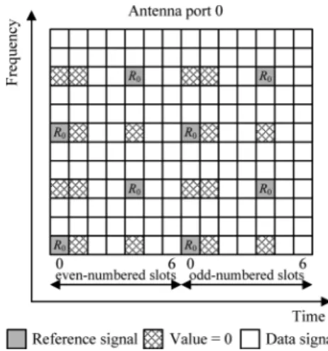
Fig. 2. Pilot locations for the first transmit antenna in the 3GPP-LTE system.
B. System Specification
In this paper, we follow the specification of 3GPP-LTE Re-lease 8 [15] to perform the analysis, simulation, and implemen-tation. The 3GPP-LTE supports a maximum 2048-point FFT size at 20-MHz bandwidth and has three MIMO configurations, 2 2, 2 4, and 4 4. In order to facilitate the operation of these MIMO configurations, 3GPP-LTE specifies the pilot pat-tern within an unit of resource block (RB) which contains twelve concatenated subcarriers. Fig. 2 shows an example of the pilot pattern in every RB of a subframe at the first antenna port, but the location may be shifted in frequency domain for dif-ferent subframes. In the simulation of this paper, we use refer-ence channel models specified by 3GPP-LTE [21] including Ex-tended Vehicular A (EVA), ExEx-tended Pedestrian A (EPA), and Extended Typical Urban (ETU) channel models.
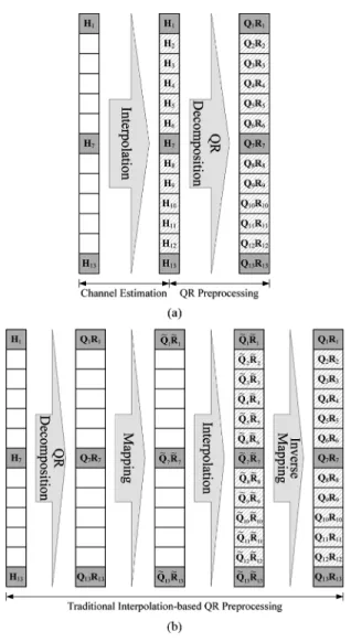
III. INTERPOLATION-BASEDQR DECOMPOSITION In general, the traditional tone-by-tone QR decomposition in a MIMO-OFDM system estimates the channel matrices by in-terpolation firstly and then performs the QR decomposition on each subcarrier as shown in Fig. 3(a), in which , and are the MIMO channel matrices for pilot subcarriers. The computational complexity of this brute-force QR decomposi-tion is extremely high for the large number of subcarriers and the high-dimension MIMO scheme. Thus, the interpolation method [18] was proposed to avoid computing the QR decomposition on every subcarrier so as to greatly reduce the overall complexity.
Fig. 3. (a) Traditional tone-by-tone QR decomposition algorithm. (b) Tradi-tional interpolation-based QR decomposition algorithm in the MIMO-OFDM system.
A. Traditional Interpolation-Based QRD
The generic interpolation-based QR decomposition al-gorithm [18] is a Gram-Schmidt-based alal-gorithm. The Gram-Schmidt orthogonalization is an iterative process expressed by
(1)
where . The and are the column
vec-tors of and , respectively, and the is the row vector of . The superscripts of and represent the Hermitian and transpose of a matrix respectively. The interpolation-based QR decomposition [18] verifies that only the Laurent polynomial (LP) matrices can be interpolated. This algorithm is conceptu-ally depicted in Fig. 3(b). Instead of estimating the channel ma-trices of all subcarriers, the algorithm only needs the channel matrices of the pilot subcarriers, , , and , and com-putes their corresponding and matrices. Because the
and matrices are not LP matrices, the polynomial interpo-lation technique can not be applied straightforward. Therefore, an invertible mapping function was introduced to obtain the
mapped LP matrices ; consequently, the
interpolation of and matrices becomes applicable. Then, the and matrices of data subcarriers are obtained by the in-verse mapping from their interpolated and matrices. The mapping and inverse mapping functions are formulated by (2) (3) and
B. Proposed Interpolation-Based QRD
The traditional Gram-Schmidt-based interpolation-based QR decomposition requires square root and division operations (1) and the mapping function. Thus, we try to further reduce these calculations by exploring (1) in a 2 2 MIMO system as an example. The 2 2 QR decomposition is written as
Then, according to (2), the mapped and matrices become
(4) and
(5) We found that all entries in the and matrices have no square root and division operations and all product terms in the
and can be found in the entries of and its Hermitian matrix , where
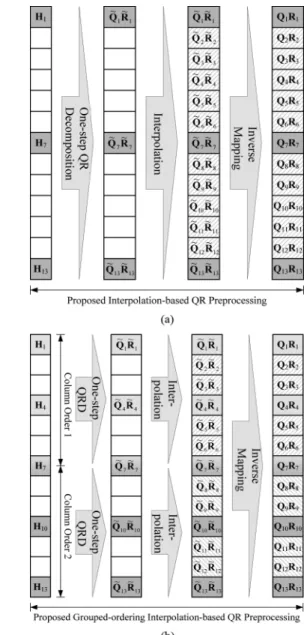
This property exists in any MIMO dimensions. Accordingly, we propose a modified interpolation-based QR decomposition (MIQRD) algorithm which computes the Hermitian matrix of the channel matrix before performing the QR decomposition. Then, the and matrices are computed directly from the en-tries of channel matrix and its corresponding Hermitian matrix with only multiplication and addition. After the and ma-trices are calculated by this one-step processing, the subsequent processes are the same as the traditional interpolation-based QR decomposition algorithm such as interpolation and inverse map-ping. The proposed algorithm can be illustrated in Fig. 4(a).
Furthermore, we extend the proposed algorithm to the 4 4 QR decomposition to show its scalable property. The proposed one-step processing is divided into several micro steps ac-cording to the number of transmit antennas, and these micro steps are performed sequentially as follows:
(6a)
(6b)
(6c)
(6d)
(6e) These sequential processes are similar to the order of Gram-Schmidt algorithm. The first column of the and the first row of the are computed firstly. Then, the second column and the second row are computed by utilizing the results of the previous micro-step. The other columns and rows of the
and can also be deduced by analogy.
The proposed algorithm features a scalability property for dif-ferent MIMO schemes. In the practical MIMO-OFDM system,
Fig. 4. Proposed interpolation-based QR decomposition for (a) the same column order and (b) the grouped column order.
the equivalent channel matrix may be not square because of non-full-rank channel or system deployment. For example, for a 4 3 channel matrix, the dimension of corresponding Her-mitian matrix is 3 3. Therefore, calculations for (6e) and
or , where , in (6b)–(6e) can be eliminated.
In summary of (6b)–(6e), for the scalable channel
ma-trix and , – represent the calculations for
, – for , and for , and
for . Without loss of generality, if the and of an channel matrix are computed, all the and ma-trices of other channel matrices, where
and , can be obtained without extra
calcula-tions in the proposed algorithm. Thus, the proposed algorithm features the scalability property that saves the hardware energy consumption while limited antenna resource is assigned in the system.
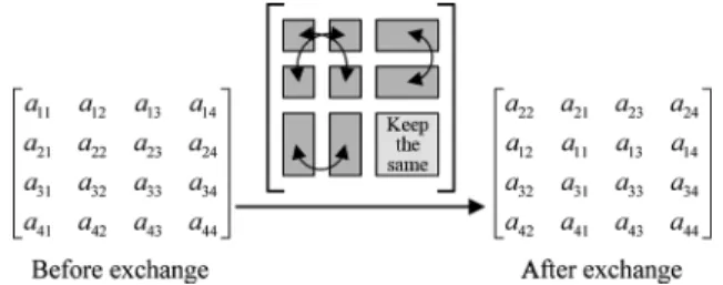
Fig. 5. Hermitian matrix before and after exchanging order of and .
TABLE I
RELATIONSHIPS OFEXCHANGING AND
C. Application to Sorted QR Decomposition
In the QR-based MIMO detection, sorted QR decomposi-tion is usually applied to improve the detecdecomposi-tion performance. However, the traditional interpolation-based QR decom-position becomes inapplicable in this situation because
, and have different column
orders. In order to solve this ordering problem, we propose a grouped-ordering modified interpolation-based QR decompo-sition (GO-MIQRD) algorithm. We divide all subcarriers into several groups and the subcarriers in one group have the same column order. Fig. 4(b) shows an example of two groups. The traditional algorithm must perform the QR decompositions of the pilot subcarrier twice at the group boundary, such as subcar-rier 7, for two different column orders; thus, the computational complexity doubles.
Nevertheless, the proposed algorithm can obtain the and matrices of two different column orders by sharing the Her-mitian matrix entries and a few additional computations. For example, if and of one channel matrix are exchanged as the channel matrix of the other column order, all entries of Hermitian matrix for the second column order are the same as those for the original column order except that their indices are exchanged, as shown in Fig. 5. If we compute the (6b)–(6e) for the index-exchanged Hermitian matrix, the order-exchanged pertaining to the original can be calculated as listed in Table I. In this best case, only needs to be
re-com-puted, and and share the same Hermitian
ma-trix. Therefore, the computational complexity can be greatly re-duced. Assume that there are groups in an OFDM symbol and pilots in each group. The GO-MIQRD algorithm is summa-rized in the following.
1) Set .
2) Determine the column order of group .
3) Set .
4) If , change the column order of the pilot in group to the column order of group , and go to step 6 by using sharing property. Otherwise, go to the next step. 5) Calculate Hermitian matrix of pilot .
6) Set .
7) Calculate the column of and the row of 8) If , go to the next step. Otherwise, set
and go back to step 7.
9) If , go to the next step. Otherwise, set and go back to step 5.
10) Interpolate the and of these pilots to obtain the and of other subcarriers in group .
11) If , go to the next step. Otherwise, set and go back to step 2.
12) For each subcarrier, apply .
For an channel matrix, the complexity of com-puting the and matrices in the traditional algorithm [18], [22] is
where is the number of complex multiplications for com-puting Givens-rotation-based QR decomposition, and de-notes the cost of mapping function . Furthermore, the com-plexity of the proposed algorithm for the same result is
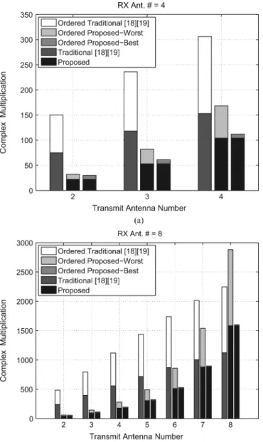
The computational complexity of the traditional and the proposed algorithms for various MIMO configurations are compared in Fig. 6. The proposed algorithm has a lower complexity than the traditional algorithm especially for the grouped-ordering scheme and the amount of reduced com-plexity varies depending on the column order. In Fig. 6(b), although the complexity of the worst case is higher than that of the traditional algorithm in 8 8 MIMO, the average cost still approximates that of the traditional algorithm. Most important of all, the proposed algorithm has much lower complexity than the traditional algorithm for the lower-rank MIMO schemes due to its scalability property.
D. High-Dimensional Extension
As described in Section III-B, the proposed algorithm can be extended to any MIMO dimensions. For the proposed one-step process, the straightforward method expands (1) and (2) sim-ilar to (4) and (5). Then, each micro step, such as (6b) and (6c), of the one-step process can be determined from these deduced forms. However, in the higher-dimension MIMO system, the equation expansion becomes very complicated and the micro
Fig. 6. Computational complexity comparisons of the traditional method and the proposed one-step method for (a) four receiving antennas and (b) eight re-ceiving antennas.
steps of the proposed one-step algorithm are difficult to be de-rived correctly. Thus, we further present an iterative algorithm that can efficiently derive the micro steps and make the proposed algorithm more useful.
As mentioned in Section III-B, the down-scalability describes
that and for , ,
etc., can be derived from and for an channel
matrix. From a reverse viewpoint, it is very possible that the up-scalability should be applicable such that and for
, , etc., can also be derived
from and for an channel matrix. By investigating the results for 2 2, 3 3 and 4 4 in (6b)–(6e), we found
that includes and terms, includes
and terms, and includes and terms.
Therefore, we deduce that for 5 5 QR matrices should include and terms and so on. According to these rules, we can derive a generalized method to compute the and
matrices for any MIMO dimensions.
1) Definition III.1: For a set ,
where , there exists a function
which is defined as
where means element is excluded in the set .
Definition III.2: For an channel matrix, the entries of and are defined as
where and .
According to Definition III.1 and Definition III.2, (6b)–(6e) can be summarized as
Similarly, all entries of the and for other MIMO dimen-sions can be derived quickly by these two definitions.
E. Interpolation Scheme
The and matrices of data subcarriers are generated by interpolation and then delivered to subsequent MIMO detector after inverse mapping. Hence, the accuracy of the interpolated
Fig. 7. SER performance results by utilizing different interpolation intervals and MCS-QR-SIC MIMO detectors for the (a) QPSK (4,4,1,1) case and (b) 16QAM (16,1,1,1) case.
and affects the final detection performance. In order to choose a proper interpolation scheme, we evaluate the detec-tion performance by utilizing the MCS-QR-SIC MIMO detector [23] under the ETU channel model because the ETU model has the longest tap delay in the 3GPP-LTE channel models. In the simulation, we used 1024 1000 data symbols and evaluated (4,4,1,1) and (16,1,1,1) cases in the 4 4 MCS-QR-SIC MIMO detector for the QPSK and 16QAM modulations, respectively. The pilot subcarrier interval in 3GPP-LTE is six subcarriers as illustrated in Fig. 2. In Fig. 7, we can see that there is a large per-formance gap between the perfect channel case and interpolated channel case especially in the high-order constellation even for the traditional channel estimation method.
Because the ETU channel is very frequency selective, short-ening interpolation interval is a possible method to improve the accuracy of interpolation. In Fig. 7, the symbol error rate (SER) performances of utilizing different interpolation inter-vals show that the detection performance is improved with a shorter interpolation interval. Thus, we can perform time-domain interpolation first to generate additional pseudo-pilot channels, and then the pilot subcarrier interval in the
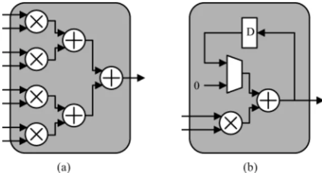
frequency-Fig. 8. Basic processing elements (a) norm and (b) MAC.
domain interpolation can be shortened from six to three subcar-riers. The simulation shows that the performance degradation is small by using linear polynomial interpolation scheme when is around 16 dB and 20 dB for the QPSK and 16 QAM modulations, respectively.
IV. TIMINGSCHEDULEANALYSIS
The proposed one-step process [see (6a)–(6e)] has two spe-cial properties. The first property is that all computations are composed of addition and multiplication operations. Thus, two basic hardware elements, norm and multiplication-and-accumu-lation (MAC), are proposed to implement these operations, as shown in Fig. 8. The norm element calculates the inner product and the MAC element accumulates the products. According to the complexity analysis in Section III-C, many norm and MAC elements are required to realize parallel implementation, espe-cially in the high-dimension MIMO system. The second prop-erty is that there exists data dependency between each micro step in the one-step process. Therefore, we must carefully parti-tion the algorithm into several subparallel computaparti-tions on the norm and MAC elements. The most important design issue is to balance the tradeoff between the hardware complexity and the computation cycle count with an appropriate subparallel hard-ware architecture and an efficient timing schedule of all opera-tions.
We use norms and MACs, that is complex mul-tipliers for receive antennas, to approach the cycle bound, so that the hardware efficiency can approach 100%. As the in-creases, the design complexity grows enormously because there is a large number of the norm and MAC combinations, and scheduling their operations for the optimal product, where is the hardware complexity defined as the number of complex multipliers and is the computational cycle count, becomes very difficult.
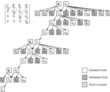
Therefore, we propose a method to obtain the optimal timing schedule by programming. First, in order to apply the scala-bility property to the timing schedule, we construct a depen-dency tree to determine the output order of entries of and , as shown in Fig. 9. Then, we can further expand the tree for according to the Definition III.1 and Definition III.2. Fig. 10 shows the expanded tree structure for . We can find that all computations in one-step process can be covered by
all possible , where ,
and . Thus, we use an -bit
Fig. 9. Output order tree of and for 4 4 channel matrix.
Fig. 10. Dependency tree of for 4 4 channel matrix.
the existence of the corresponding , and “0” represents its ab-sence. For example, “0101” represents {1, 3} and “1110” rep-resents {2, 3, 4}. Then, a dependency tree can be built up based on the data dependency of the micro-steps. For a given com-bination of the norms and MACs, we can traverse the depen-dency tree to schedule the operations of the proposed algorithm on the norms and MACs. One node must be scheduled after all of its child nodes have been scheduled. Note that because the computation of Hermitian matrix has the highest priority, we schedule dedicated norm elements to perform Hermitian matrix calculations to reduce the computational cycle count. After the Hermitian matrix computation is finished, the norm elements are then shared by other calculations. The MAC elements are almost scheduled for vectors because each of them occupies
Fig. 11. (a) Timing schedule results for different MIMO configurations. (b) Scheduled smallest product values for 12 12 channel matrix under dif-ferent timing constraints.
Fig. 12. Proposed MIQRD hardware architecture.
complex multipliers over several cycles. We performed the scheduling program using different combinations of norms and MACs based on these rules, and obtained the scheduled cycle count versus the hardware complexity ( multipliers) for various MIMO configurations, as shown in Fig. 11(a). If the one-step processing module must meet the throughput require-ment of the system, we can use Fig. 11(a) to obtain the min-imum hardware complexity under the constrained cycle time. On the other hand, the product versus timing constraint is plotted in Fig. 11(b). If the energy cost is the design con-straint, the optimal hardware combination can be determined by choosing the smallest timing constraint that approximates the lower-bound, that is, 200 cycles for the example of 12 12 channel matrix in Fig. 11(b).
V. HARDWAREARCHITECTURE ANDCIRCUITIMPLEMENTATION Based on the proposed interpolated-QR decomposition algo-rithm and the timing schedule program, we designed and imple-mented the QR decomposition processor for 3GPP-LTE MIMO-OFDM system. The proposed QR decomposition processor con-sists of one-step processing, interpolation and inverse mapping, as shown in Fig. 12.
A. One-Step Processing
In the system, the pilot channel matrix is updated every three cycles of the system clock and four or vectors must be
Fig. 13. Computation cycle counts for different combinations of the norm and the MAC in a 4 4 MIMO system.
Fig. 14. Timing schedule of 4 4 one-step with two norms and four MACs.
Fig. 15. Block diagram of one-step process with two norms and four MACs.
generated within four cycles for a 4 4 channel matrix. There-fore, in order to generate the and for three data sub-carriers, the timing processing constraint for the one-step pro-cessing module is twelve cycles of the operating . Then, two norms and four MACs are selected in the one-step processing module according to Fig. 13, and the final timing schedule can be derived from the scheduling program, as shown in Fig. 14. For 2 2 and 4 2 channel matrices, one-step pro-cessing requires only four cycles so that doubled clock rate is enough. The top-level block diagram of the proposed one-step process is illustrated in Fig. 15. The memory stores five
tem-poral complex values and 4 4 complex
ma-trices, including , , , and Hermitian matrix.
B. Interpolation
In 3GPP-LTE, the locations of pilot subcarriers in an OFDM symbol may be shifted in frequency domain for different sub-frames, and therefore the pilots may be not located at the edge of
Fig. 16. Three possible pilot locations at the resource block boundary.
Fig. 17. (a) Interpolation architecture of and and (b) the linear real-valued interpolator.
resource block. Three possible locations of the pilot and pseudo-pilot (estimated by time-domain interpolation) are summarized in Fig. 16. In 3GPP-LTE, the user equipment (UE) only receives the data located in the assigned resource blocks. In case 2 and case 3, the first pilot is not located in the resource block. In order to design a regular hardware architecture of the interpolation module, the first pilot channel is extrapolated by the channel es-timator.
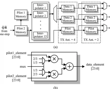
The architecture of the and interpolation is shown in Fig. 17(a), in which linear real-valued interpolators are utilized, as shown in Fig. 17(b). Because the proposed MIQRD is de-signed to output one column of and one row of per cycle, it requires fifteen real-valued interpolators, eight for and seven for calculations. The memories after the interpolators store the results for inverse mapping. If the pilot is a pseudo-pilot, it needs to be de-mapped so its result must also be stored. Besides, for 4 2 and 2 2 channel matrices, additional memories are required to wait for the processing of inverse mapping since the processing time of one-step module is shorter than that of the 4 4 case.
C. Inverse Mapping
Fig. 18(a) shows the block diagram of the inverse mapping module and it is composed of the demapping factor cal-culation and the demapper. In order to simplify the clock design,
Fig. 18. Block diagram of (a) the inverse mapping, (b) the demapping factor calculation, and (c) the parallel multiplications of demapper.
Fig. 19. Fixed-point simulation of MIQRD.
the inverse mapping hardware also operates at a quadruple fre-quency of the system clock. According to the word-length de-termined from the fixed-point simulation and the critical time
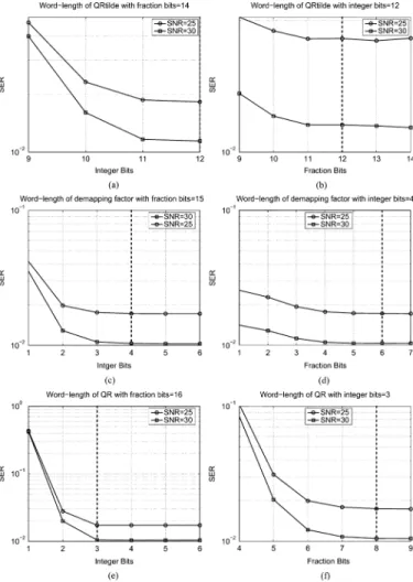
Fig. 20. SER performances of fixed point simulations for different word-lengths of and .
of the synthesis result, both of the square root and division are implemented by two-stage pipelined architecture to meet the timing constraint as depicted in Fig. 18(b). Then, 15 real-valued multipliers are used to de-map one column of and one row of
to the corresponding and , as shown in Fig. 18(c).
D. Fixed-Point Simulation
We use the symbol error rate (SER) as the metric to determine the word-length of the signal in the fixed-point simulation. Be-cause the clipping error has larger impact on the performance of the proposed architecture than the truncation error, we deter-mine the word-length of the integer part for the signal first, and then the fraction part. A fixed-point 2’s complement number is represented by (I,F), in which I and F denote the word-lengths of the integer part and the fraction part respectively. According to the fixed point simulation in Fig. 19, the word-length of the sig-nals is chosen to achieve with QPSK and 16QAM modulations. Fig. 20 shows the SER performances of fixed point simulations for different word-lengths of and in 4 4 16 QAM system. Table II lists the word-length of the signals in the three modules. The word-length for the and is larger than those of others and dominates the operating frequency because the dynamic range of grows along with the dimension of channel matrix. The processing time schedules of the whole MIQRD processor for different channel matrices are shown in Fig. 21. The latencies for and cases are 27 cycles and 15 cycles, respectively, to produce one column/row vector per cycle at the MIQRD output.
E. Circuit Implementation
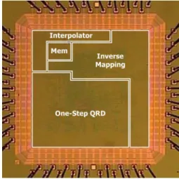
The proposed interpolation-based QR decomposition pro-cessor was designed and implemented using UMC 90-nm one-poly nine-metal CMOS technology. The processor
occu-pies with core area. Fig. 22 shows the
micrograph of the chip. The function of the chip was verified and the performance measured using a digital test station. The chip consumes 49 mW at its maximum frequency 140.65 MHz. The comparison of the implementation results of the proposed and other QR decomposition processors is summarized in
Fig. 21. Processing time of each module in MIQRD for (a) channel matrix and (b) channel matrix.
TABLE II
WORD-LENGTHS OF THEMODULES IN THEPROPOSEDMIQRD ARCHITECTURE
Table III. Since the proposed interpolation-based QR decom-position processor also executes the task of channel estimation, it requires a larger gate count than the other works. However, the throughput of the proposed chip is 35.16 MQRD/s and the normalized throughput of our chip is much higher than those of other works based on the tone-by-tone sole QR decomposition algorithm. Although raw gate-count number is very large in our design, the gate efficiency, either including or excluding the channel estimation, is not the worst as compared to others in the literature. Therefore, this architecture is suitable for designing a high-throughput QR decomposition processor for MIMO-OFDM receiver.
VI. CONCLUSION
This paper proposes a scalable interpolation-based QR de-composition algorithm and a grouped-ordering scheme for the
Fig. 22. Chip micrograph.
MIMO-OFDM system. The derived general equations and the proposed timing scheduling method facilitate the architecture design of the proposed algorithm. A configurable interpola-tion-based QR decomposition processor is also presented in the work. The processor supports 2 2, 4 2 and 4 4 channel matrices to meet the requirements of the next generation wireless communication system. Meanwhile, it features much higher data throughput at balancing the hardware cost that is very suitable for low-complexity MIMO-OFDM systems.
TABLE III COMPARISONRESULTS
ACKNOWLEDGMENT
The authors would like to thank Chip Implementation Center of National Applied Research Laboratories in Taiwan for tech-nical support.
REFERENCES
[1] G. J. Foschini, “Layered space-time architecture for wireless commu-nication in a fading envirenment when using multiple antennas,” Bell
Lab. Tech. J., vol. 1, no. 2, pp. 41–59, 1996.
[2] P. W. Wolniansky, G. J. Foschini, G. D. Golden, and R. A. Valenzuela, “V-BLAST: An architecture for realizing very high data rates over the rich-scattering wireless channel,” in Proc. URSI Int. Symp. Signals,
Systems, and Electronics, Sep. 1998, pp. 295–300.
[3] R. Böhnke, D. Wübben, V. Kühn, and K. D. Kammeyer, “Re-duced complexity MMSE detection for BLAST architectures,” Proc.
Globecom ’03, vol. 4, pp. 2258–2262, Dec. 2003.
[4] E. Agrell, T. Eriksson, A. Vardy, and K. Zeger, “Closest point search in lattices,” IEEE Trans. Inform. Theory, vol. 48, no. 8, pp. 2201–2214, Aug. 2002.
[5] K. W. Wong, C. Y. Tsui, R. S. K. Cheng, and W. H. Mow, “A VLSI ar-chitecture of a K-best lattice decoding algorithm for MIMO channels,” in Proc. IEEE Int. Symp. Circuits and Systems, May 2002, vol. 3, pp. 273–276.
[6] P. Luethi, A. Burg, S. Haene, D. Perels, N. Felber, and W. Fichtner, “VLSI implementation of a high-speed iterative sorted MMSE QR de-composition,” in Proc. IEEE Int. Symp. Circuits and Systems, May 2007, pp. 1421–1424.
[7] C. K. Singh, S. H. Prasad, and P. T. Balsara, “VLSI architecture for matrix inversion using modified Gram-Schmidt based QR decomposi-tion,” in Proc. 20th Int. Conf. VLSI Design (Held Jointly with 6th Int.
Conf. on Embedded Systems), Jan. 2007, pp. 836–841.
[8] P. Salmela, A. Burian, H. Sorokin, and J. Takala, “Complex-valued QR decomposition implementation for MIMO receivers,” in Proc. IEEE
Int. Conf. Acoustics, Speech and Signal Processing, Mar. 2008, pp.
1433–1436.
[9] K. H. Lin, R. C. H. Chang, C. L. Huang, F. C. Chen, and S. C. Lin, “Implementation of QR decomposition for MIMO-OFDM detection systems,” in Proc. 15th IEEE Int. Conf. Electronics, Circuits and
Sys-tems, Aug. 2008, pp. 57–60.
[10] P. Luethi, C. Studer, S. Duetsch, E. Zgraggen, H. Kaeslin, N. Felber, and W. Fichtner, “Gram-Schmidt-Based QR decomposition for MIMO detection: VLSI implementation and comparison,” in Proc. IEEE Asia Pacific Conf. Circuits and Systems, Nov. 2008, pp. 830–833.
[11] D. Patel, M. Shabany, and P. G. Gulak, “A low-complexity high-speed QR decomposition implementation for MIMO receivers,” in Proc.
IEEE Int. Symp. Circuits and Systems, May 2009, pp. 33–36.
[12] R. C. H. Chang, C. H. Lin, K. H. Lin, C. L. Huang, and F. C. Chen, “Iterative QR decomposition architecture using the modified Gram-Schmidt algorithm for MIMO systems,” IEEE Trans. Circuits Syst. I,
Reg. Papers, vol. 58, no. 5, pp. 1–8, May 2010.
[13] IEEE 802.16e-2005-Amendment 2: Physical and Medium Access
Con-trol Layers for Combined Fixed and Mobile Operation in Licensed Bands, IEEE Std. 802.16, 2006.
[14] IEEE 802.11n-2009-Amendment 5: Enhancements for Higher
Throughput, IEEE Std. 802.11, 2009.
[15] 3GPP TS 36.211-Physical Channels and Modulation, 3GPP Technical Specification, Rev. 8.9.0 2009.
[16] IEEE.16m-Amendment: Air Interface for Fixed and Mobile Broadband Wireless Access Systems—Advanced Air Interface, IEEE Draft, Rev. D5 2010.
[17] 3GPP TR 36.814-Further Advancements for E-UTRA Physical Layer Aspects 2010, 3GPP Technical Report, Rev. 9.0.0.
[18] D. Cescato, M. Borgmann, H. Bölcskei, J. Hansen, and A. Burg, “Inter-polation-based QR decomposition in MIMO-OFDM systems,” in Proc.
IEEE 6th Workshop on Signal Processing Advances in Wireless Com-munications, Jun. 2005, pp. 945–949.
[19] D. Wübben and K. D. Kammeyer, “Interpolation-based successive in-terference cancellation for per-antenna-coded MIMO-OFDM systems using P-SQRD,” in Proc. IEEE Workshop on Smart Antennas, Mar. 2006.
[20] P. L. Chiu, L. Z. Huang, and Y. H. Huang, “Scalable interpo-lation-based QRD architecture for subcarrier-grouped-ordering MIMO-OFDM system,” in Proc. 43th IEEE Asilomar Conf. on
Signals, Systems, and Computers, Nov. 2009, pp. 708–712.
[21] 3GPP TS 36.101-User Equipment (UE) Radio Transmission and Re-ception 2010, 3GPP Technical Specification, Rev. 8.9.0.
[22] A. Burg, “VLSI Circuits for MIMO Communication Systems,” Ph.D., Swiss Federal Inst. Technol., Zurich, Switzerland, 2006.
[23] P. L. Chiu and Y. H. Huang, “A scalable MIMO detection architec-ture with non-sorted multiple-candidate selection,” in Proc. IEEE Int.
Symp. Circuits and Systems, May 2009, pp. 689–692.
Po-Lin Chiu (M’09) was born in Tainan, Taiwan,
R.O.C., in 1975. He received the B.S. and M.S. degrees in electrical engineering from National Cen-tral University, Taoyuan, Taiwan, R.O.C., in 1997 and 1999, respectively. He is currently pursuing the Ph.D. degree at the Department of Communication Engineering, National Chiao-Tung University, Hsinchu, Taiwan.
Since 2004, he has been with the Department of Communication Engineering, National Chiao-Tung University. He is also a Member of Technical Staff at ITRI, Hsinchu. His research interests include the baseband signal processing, multiple-input multiple-output signal processing, and VLSI design of wireless communications.
Lin-Zheng Huang was born in Taiwan in 1985. He
received the B.S. degree in electronic engineering from National Cheng Kung University, Tainan, Taiwan, R.O.C., in 2007 and the M.S. degree in electrical engineering from National Tsing-Hua University, Hsinchu, Taiwan, R.O.C., in 2010. He is currently in military service in Taiwan, R.O.C.. His research interests include VLSI design and implementation of the communication applications.
Li-Wei Chai was born in Taiwan, R.O.C., in 1984.
He received the B.S. degree in communications engineering from Feng-Chia University, Taichung, Taiwan, in 2008 and the M.S. degree in commu-nications engineering from National Tsing-Hua University, Hsinchu, Taiwan, in 2010.
He is currently in military service in Taiwan. His research interests include VLSI design and implementation of the communication applications.
Yuan-Hao Huang (S’98–M’02) was born in Taiwan,
R.O.C., in 1973. He received the B.S. and Ph.D. de-grees in electrical engineering from National Taiwan University, Taipei, Taiwan, in 1995 and 2001, respec-tively.
He was a Member of Technical Staff with VXIS Technology Corporation, Hsin-Chu, Taiwan, from 2001 to 2005. Since 2005, he has been with the Deparment of Electrical Engineering, Institute of Communications Engineering, National Tsing-Hua University, Taiwan, where he is currently an Assis-tant Professor. His research interests include VLSI design for digital signal processing systems and telecommunication systems.
Dr. Huang is a Technical Committee Member of the Signal Processing Sys-tems (DiSPS) Technical Committee of the IEEE Signal Processing Society.