Cheng-Hung Shih, Ikai Lo, Shuo-Ting You, Cheng-Da Tsai, Bae-Heng Tseng, Yun-Feng Chen, Chiao-Hsin Chen, Chuo-Han Lee, Wei-I Lee, and Gary Z. L. Hsu
Citation: AIP Advances 4, 127120 (2014); doi: 10.1063/1.4904030 View online: http://dx.doi.org/10.1063/1.4904030
View Table of Contents: http://scitation.aip.org/content/aip/journal/adva/4/12?ver=pdfcov Published by the AIP Publishing
Articles you may be interested in
Investigation of CuGaSe2/CuInSe2 double heterojunction interfaces grown by molecular beam epitaxy AIP Advances 5, 027120 (2015); 10.1063/1.4908229
Successful growth of Cu2Se-free CuGaSe2 by migration-enhanced epitaxy J. Vac. Sci. Technol. B 30, 02B126 (2012); 10.1116/1.3690456
Growth of polycrystalline Cu ( In , Ga ) Se 2 thin films using a radio frequency-cracked Se-radical beam source and application for photovoltaic devices
Appl. Phys. Lett. 91, 041902 (2007); 10.1063/1.2766669
Reaction kinetics of CuInSe 2 thin films grown from bilayer InSe/CuSe precursors J. Vac. Sci. Technol. A 23, 310 (2005); 10.1116/1.1861051
Epitaxial growth of CuInS 2 on sulphur terminated Si(001) Appl. Phys. Lett. 72, 2733 (1998); 10.1063/1.121074
AIP ADVANCES 4, 127120 (2014)
The growth of heteroepitaxial CuInSe
2on free-standing
N-polar GaN
Cheng-Hung Shih,1Ikai Lo,2,aShuo-Ting You,2Cheng-Da Tsai,2
Bae-Heng Tseng,3Yun-Feng Chen,3Chiao-Hsin Chen,3Chuo-Han Lee,4 Wei-I Lee,4and Gary Z. L. Hsu5
1Multidisciplinary Science Research Center, National Sun Yat-Sen University,
Kaohsiung 80424, Taiwan ROC
2Department of Physics, Center for Nanoscience and Nanotechnology, National Sun Yat-Sen
University, Kaohsiung 80424, Taiwan ROC
3Department of Materials and Optoelectronic Science, National Sun Yat-Sen University,
Kaohsiung 80424, Taiwan ROC
4Department of Electrophysics, National Chiao Tung University, Taiwan ROC 5United Crystal Corporation, No. 243-3, Wenshan 36061, Miaoli, Taiwan ROC
(Received 22 September 2014; accepted 27 November 2014; published online 9 December 2014)
We report that chalcopyrite CuInSe2thin films were grown on free-standing N-polar GaN (000¯1) by molecular beam epitaxy. X-ray diffraction showed that the CuInSe2 thin film was grown in (112) orientation, and its peak of rocking curve with full width at half maximum of about 897.8 arc-sec indicated the epitaxial growth of CuInSe2 (112) film on N-polar GaN. Microstructure analysis of the CuInSe2 showed that the large lattice mismatch (28.5%) between CuInSe2 and GaN is accommodated by domain matching, and no interface reaction occurs between CuInSe2and GaN. Our experimental results show that GaN is stable for the epitaxial growth of CuInSe2thin film, which exhibits a promising potential for optoelectronic applications. C2014
Au-thor(s). All article content, except where otherwise noted, is licensed under a Creative Commons Attribution 3.0 Unported License.[http://dx.doi.org/10.1063/1.4904030]
I. INTRODUCTION
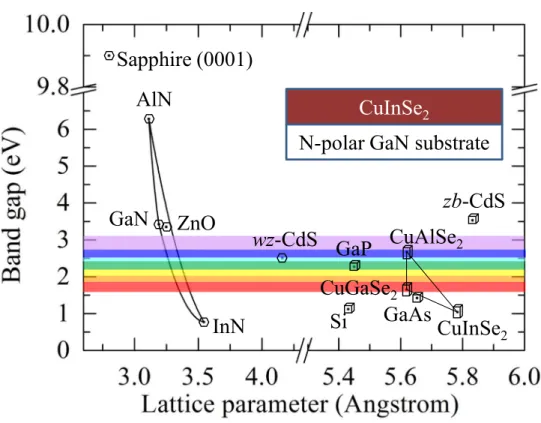
CuInSe2 (CIS) is a chalcopyrite structure semiconductor with a direct band gap of ∼1 eV and high absorption coefficient of 107 m-1, which was widely used in the field of solar cell.1
Moreover, the Cu(In,Al,Ga)Se2ternary chalcopyrite semiconductors are promising candidates for light emitting devices in the visible and ultraviolet spectral ranges.2The band gap range is from
1.0 eV (CuInSe2) to 2.6 eV (CuAlSe2) by varying the composition of Cu/III-element, as shown in Fig. 1. In general, the conventional polycrystalline CIS thin film solar cell is fabricated by the configuration of soda-lime-glass (SLG)/molybdenum (Mo)/Cu(In,Ga)Se2/CdS/ZnO.1The back contact of Mo shades the light from back wall of the solar cell and reduces the area of optical absorption. Therefore, using a transparent back contact can avoid the problem of shade from the back contact of Mo. In addition, single crystalline CIS grown on wide band gap material is essential to optimize its optical properties for the optoelectronic applications. To grow a single crystal CIS thin film, a lattice-matched substrate can reduce structural defects in the CIS thin film. The epitaxial growth of CIS on single crystal substrates, including GaAs,3Si,4and GaP5has been investigated
by different groups. Because the bang gap (Eg) of these substrates is much lower than 3.0 eV, the non-transparent and low band-gap substrates create a problem of shade with wild absorption of photons, leading to the decreasing of device efficiency. The growth of CuInSe2 thin film on a wide band-gap substrate (Eg >3.0 eV) was scarcely reported in the literature. It was mentioned
ae-mail:[email protected], Tel:+886-7-525-3734, FAX: +886-7-525-3709
FIG. 1. Band gap energy and lattice constant of various III-nitride and chalcopyrite semiconductors at room temperature. Inserts show the schematic of sample structure. Abbreviations of “wz” and “zb” indicate wurtzite and zinc blende, respectively.
by Hofmann et al. in the high crystalline quality of ZnO (Eg= 3.32 eV) thin film grown on CuInSe2 thin film.6 They found that an interface reaction between CuInSe2 and ZnO took place to form a ZnSe layer during the deposition of CuInSe2 thin film. The ZnSe layer will affect the band alignment between CuInSe2and ZnO. In addition to the effect of band alignment, the interface reaction can produce unnecessary impurities and structural defects in the CuInSe2layer as well. In contrast to ZnO, GaN is also a wurtzite material but has a wider band gap (3.42 eV) and lower resistivity, which provide electronic properties to guaranty higher efficient performance of CIS for optoelectronic applications. The bang-gap energies versus the lattice parameters for these materials are plotted in Fig.1. It is shown that the lattice size and crystal structure are quite different between
CIS (tetragonal, a: 5.784 Å, c: 11.621 Å) and GaN (wurtzite, a: 3.189 Å, c: 5.185 Å). In spite of these differences, we were able to grow the heteroepitaxial CIS thin film, directly, on a c-plane free-standing N-polar GaN substrate, as shown schematically in the inset of Fig.1, which demon-strated the growth of I-III-VI2chalcopyrite compounds on an III-nitride substrate. In addition, the light refraction index of wurtzite GaN is nGaN =2.78 at 3.4 eV7 and that of chalcopyrite CIS is nCIS=2.91 at 0.8 eV.8The critical angle of total internal reflection, θc=sin−1(nGaN/nCIS) = 74.1◦, benefits the CIS/GaN heterojunction a good waveguide structure for optical application. In general, a GaN thin film (>4 µm) can be grown on sapphire (0001) substrate to form a GaN template substrate. In order to fabricate vertical CIS/GaN device, we grow CIS thin film on free-standing N-polar GaN substrate i.e. removed sapphire substrate. In this paper, we show the epitaxial growth of CIS thin film on free-standing N-polar GaN (000¯1) substrate by molecular beam epitaxy. It was found that the tetragonal CIS was epitaxially grown on wurtzite GaN and no interface reaction was observed at the interface between CIS and GaN. Our experimental results show that III-nitride is a good substrate material for the epitaxial growth of chalcopyrite semiconductor. It can combine the advantages of III-nitride and I-III-VI2 chalcopyrite compound to create a better design for high-efficiency solar-cell and light emitting devices.
127120-3 Shih et al. AIP Advances 4, 127120 (2014)
II. EXPERIMENTAL DETAILS
The growth of CIS films by molecular beam epitaxy (MBE) was performed on 1 × 1 cm2 free-standing N-polar GaN (000¯1) substrate at a substrate temperature 500◦C and a growth rate of 1.0 µm/hr. The free-standing N-polar GaN (000¯1) substrate was prepared by HVPE. The thick N-polar GaN film (thickness: 150 µm) was grown on sapphire (0001) substrate. After thin film growth, the sapphire substrate was removed by laser lift-off technique to obtain the free-standing GaN substrate. The free-standing N-polar GaN substrate was polished by chemical mechanical polish (CMP) to achieve atomic flat surface (roughness < 0.5 nm) after lift-off from the sapphire substrate. Two samples S1and S2were grown with flux ratio of Cu/In = 1.2 and 0.82 under the growth condition of Cu-rich and In-rich, respectively. Because of the high vapor pressure of sele-nium (Se), the Se flux was kept over pressured during the epitaxial growth to avoid the deficiency of Se in the thin film.
By using the X-ray diffraction measurements of 2 theta-omega and double crystal rocking, we evaluated the crystal structure and quality of the samples, respectively. The X-ray diffraction measurements were performed by X-ray diffractometry (XRD, model: Bede D1) with Si (220) dual channel monochromator delivering Cu Kα1X-ray. The measurement of reflection high-energy electron diffraction (RHEED) for the growth of CIS on N-polar GaN substrate was taken in a MBE chamber (Veeco Applied-EPI 930) with the settings of 15 kV and 1.4 mA. The composition and surface morphology of the samples were measured by field emission scanning electron microscope (FE-SEM, model: Jeol-6700), equipped with an energy-dispersive X-ray spepctroscope (EDS). The FE-SEM was operated with the accelerated voltage of 10 kV. The surface morphology of the sam-ples was observed by atomic force microscope (AFM). AFM images were taken with tapping mode by silicon probe and the scanning data were characterized by software NanoScope (R) III (Digital Instruments, version 5.12r2). The microstructure of CuInSe2 was characterized by field emission transmission electron microscope (FE-TEM) (Phillips, model Techni F-20). The FE-TEM was oper-ated with the acceleroper-ated voltage of 200 kV. The cross-sectional TEM specimens were prepared by focus ion beam (FIB) (Seiko Inc., model SII-3050). The FIB was performed with accelerated voltage of 30 kV to cut the samples roughly and then refined the sample further by accelerated voltage of 5 kV. The crystal phase of CIS thin film was studied by Raman spectroscopy at room temperature and excited with Nd-YAG laser operating at 532 nm (Witec, model alpha 300 R). In addition, the crystal structure of CIS and GaN was simulated by software CaRine to investigate the growth mechanism of CIS on GaN. The software CaRine can simulate not only crystal structure but also electron diffraction pattern.
III. RESULTS AND DISCUSSION
Figure 2(a)shows the X-ray 2θ-ω scan of bare c-plane N-polar GaN substrate, Cu-rich and In-rich CIS grown on the N-polar GaN substrate, labeled as S0, S1 and S2, respectively. It shows the formation of polar surface for CIS {112}, which is epitaxially grown on N-polar GaN substrate. However, we found that CIS (220) and CIS (312) diffraction peaks appear in the X-ray spectrum of In-rich CIS thin film (S2), indicating the film with a polycrystalline structure. The crystal quality of CIS thin film was evaluated by double crystal X-ray rocking curve. The results of rocking curve measurement at CIS (112) are shown in Fig.2(b). The full width at half-maximum (FWHM) of the Cu-rich CIS and In-rich CIS samples is 897.8 and 2552.7 arc-sec, respectively. The FWHM value of Cu-rich CIS (S1) is much smaller than that of In-rich CIS (S2), which indicates the high-quality of Cu-rich CuInSe2. In addition, compared to the diffraction angle of relaxed CIS (112), the 2θ value of CIS epi-layer (2θ: 26.683◦) is larger than that of the relaxed CIS (JCPDS card No.: 87-2265, 2θ: 26.649◦). It indicates that the epi-layers are under compressive stress along the growth direction.
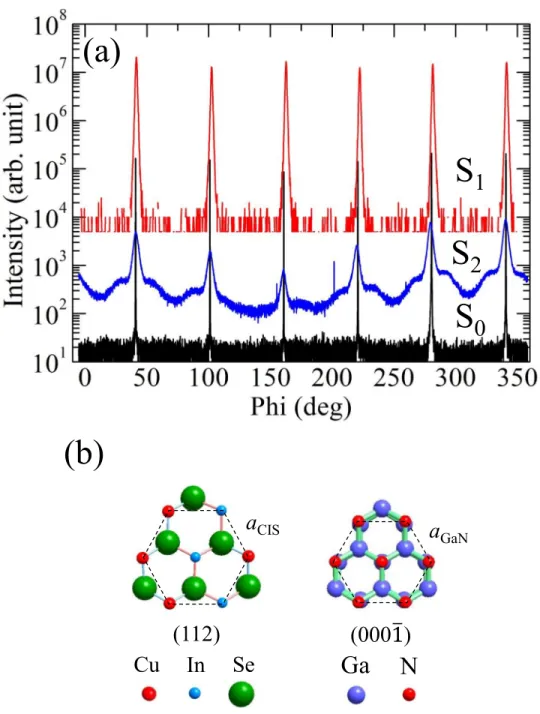
To determine the epitaxial relationship between the CIS films and the GaN substrate, XRD Phi-scans were further carried out. Figure3(a)shows the Phi-scan spectrum recorded at CIS {204} (Chi= 35.8◦, 2θ= 44.2◦) for Cu-rich and In-rich CIS samples, along with that for GaN {10¯12} (Chi = 45.1◦, 2θ= 48.1◦). Six peaks displayed in the Phi-scan spectrum represent the six-fold symmetry in the CIS (112). It is interesting that the Phi-scan spectrum of In-rich CIS (S2) shows
FIG. 2. (a) XRD data of CIS grown on c-plane N-polar GaN substrate. The labels S0, S1and S2indicate N-polar GaN substrate, Cu-rich and and In-rich CIS, respectively. (b) The rocking curve and the FWHM value of Cu-rich and and In-rich CIS (112), respectively. The solid lines indicate the diffraction position of strain free of GaN (000¯1) and CIS (112), respectively. Unknown peak labels “?”.
a different diffraction profile. In the Phi-scan spectrum of In-rich CIS (S2), two shoulders appear symmetrically at the sides of main diffraction peaks. The angle of the two shoulders differs from the main diffraction peak by 12◦. The shoulders could arise from tilted crystal plane of CIS {204}. On the other hand, from the Phi-scan and rocking curve measurements, it can conclude that the Cu-rich
127120-5 Shih et al. AIP Advances 4, 127120 (2014)
FIG. 3. (a) In-plane Phi scans of CIS thin films and N-polar GaN. S0Recorded at GaN {10¯12} with a tilt angle (Chi) of 45.1◦; S
1and S2recorded at Cu-rich and In-rich CIS {204} with a tilt angle of 35.8◦. (b) Projections of CIS to the (112) and GaN to (0001). The lengths of CIS (112) aCISand GaN (000¯1) aGaNare 4.10 Å and 3.19 Å, respectively.
CIS film (S1) can be grown epitaxially on the N-polar GaN substrate with an orientation of CIS (112)//GaN(000¯1).
According to the crystal structure of CIS (112), i.e., a pseudo-hexagonal basal plane, CIS (112) can be epitaxially grown on six-fold symmetry {111} zinc blende substrate, such as GaAs (111)9
or Si (111).4In contrast to {111} zinc blende structure, the crystal symmetry of c-plane GaN is a
six-fold hexagonal wurtzite structure as well. To understand the epitaxial growth of CIS on GaN, the crystal structure models of CIS (112) and GaN (000¯1) are shown in Fig.3(b). Figure3(b)shows the projection of CIS (112), which exhibits a clear hexagonal feature. The side length of CIS (112) is aCIS= 4.10 Å. The side length of CIS (112) is greater than that of GaN (000¯1), i.e., aGaN= 3.19 Å.
The lattice mismatch between CIS and GaN is: (aCIS- aGaN)/aGaN= 28.5 %. According to the result of lattice mismatch, the possibility of epitaxial growth of CIS (112) on N-polar GaN is challenging. In contrast to conventional lattice matching epitaxy growth, the lattice matching epitaxy during thin film growth is possible when the lattice mismatch between the film and the substrate is less than 7%-8%. In large lattice mismatch systems, the epitaxial growth of thin films is possible by match-ing of domains where integrate multiples of major lattice planes to match across the interface of substrate, i.e., domain matching epitaxy (DME).10The domain mismatch can be expressed: f
m/n= (n×afilm– m×asubstrate)/ (m×asubstrate). Therefore, the domain mismatch for CIS (112) grown on GaN (000¯1), fm/n= (n×aCIS– m×aGaN)/ (m×aGaN), gives to m= 5, n = 4 and f5/4= 2.8%.
Surface morphology of the CIS thin films was characterized by SEM and AFM. Figure 4(a)
and4(c)shows the SEM images of the Cu-rich and In-rich CIS samples, respectively. Both surface morphologies of Cu-rich and In-rich CIS samples show a rough surface. However, the surface of Cu-rich CIS (S1) reveals island structure which exhibits a three-dimensional (3D) Stranski-Krastanov heteroepitaxial growth mode, where there is appreciable lattice mismatch between the epilayer and substrate.11 In contrast to Cu-rich CIS, the surface morphology of In-rich CIS (S2) reveals triangular grain-like surface. The grain-like surface indicates a polycrystalline structure, corresponding to the result of XRD shown in Fig. 2(a). Besides, the composition of the two CIS thin films was quantified by EDS measurement, which gave the Cu/In ratio in S1and S2to be 1.42 and 0.61, respectively. It confirms indeed S1 to be Cu-rich CIS and S2to be In-rich CIS. AFM was used to characterize the surface morphology and surface roughness, and the results are shown in Fig.4(b)and4(d). The root-mean-square surface roughness of Cu-rich CIS (S1) and In-rich CIS (S2) was analyzed to be 25.3 nm and 23.5 nm, respectively. According to the results of SEM and AFM,
FIG. 4. SEM images of Cu-rich and In-rich CIS were taken showing in (a) and (c). AFM images of Cu-rich and In-rich CIS by 5 µm × 5 µm scan. (b) In-rich CIS, (d) Cu-rich CIS. Squares indicate the executed area of RMS analysis.
127120-7 Shih et al. AIP Advances 4, 127120 (2014)
it clearly shows two different surface morphologies between Cu-rich CIS and In-rich CIS. We found that the Cu-rich CIS (S1) has bigger grains than the In-rich CIS (S2). It means that the adatoms have a longer diffusion distance under the growth condition of Cu-rich.
In order to investigate the mechanism of domain matching epitaxy growth (DME) for CIS on N-polar GaN, we performed the TEM measurement on Cu-rich thin films. The TEM specimens of Cu-rich CIS thin films were prepared by FIB. Figure5(a) shows the high resolution TEM image at Cu-rich CIS/GaN interface. In the high resolution TEM image of the interface, we did not find amorphous structure forming at the interface in spite of lattice mismatch between CIS and GaN. Figure 5(b) shows the inversed fast Fourier transform (IFFT) image from Figure 5(a). Detailed analysis of Fig.5(b)can verify that the epitaxy of CIS grown on GaN occurs by domain matching,
FIG. 5. Cross-section TEM images of Cu-rich CIS on N-polar GaN substrate. (a) Bright field TEM image of Cu-rich CIS taken along CIS [110]; (b) High resolution TEM image taken at the interface region of Cu-rich CIS. (c) EDS line profile taken at the interface region of Cu-rich CIS. The dash line in (c) indicating interface. Insert is STEM image indicating the region of probe of EDS line profile.
which yields to domain matching epitaxy with m= 5 (10¯10) planes of GaN and n = 4 (112) plane of CIS. The supplementary planes in each domain, marked in Fig. 5(b), permit the f5/4 domain matching epitaxy of CIS on GaN. The result of the IFFT image is in agreement with the model of domain matching epitaxy with domain mismatch of 2.8% in Fig.3(b). To inspect the HR-TEM image, the lattice d-spacing of CIS {112} measured from Fig. 5(a)is 0.351 nm which is larger than that of relaxed CIS {112} (d-spacing: 0.334 nm) [JCPDS card No.: 87-2265], indicating that the CIS film is under compressive stress. This result agrees with the result of X-ray diffraction. In addition, we considered that another crystal structure of CIS could form in the CIS thin film, i.e. wurtzite structure.12The lattice parameters of hexagonal wurtzite CIS are a= 4.08 Å and c =
6.69 Å. Comparing the lattice parameters between tetragonal CIS (112) and wurtzite CIS, the lattice parameters of wurtzite CIS closes to tetragonal CIS (112) (a= 4.10 Å). However, the measured angle of {112} plane is 54.2◦which is coincident to the angle between (004) and (¯112) chalcopyrite CIS (54.8◦). Therefore, in spite of the similar lattice parameter between wurtzite CIS and tetragonal CIS (112), we did not find that any wurtzite structure of CIS formed at the interface of CIS/GaN.
In addition, CIS has a polar surface on {112} plane. The orientation of surface polarity will affect the band gap profile of p-n junction. The polar direction of CIS will be determined by initial growth of the CIS thin film. GaN is a hexagonal wurtzite structure, which offers two nonequivalent surfaces on the c-plane of GaN due to the polarity of Ga-N bilayers, resulting in two types of dangling-bonds: cationic Ga dangling-bond for (0001) surface and anionic N dangling-bond for (000¯1) surface. The polar surface of GaN will affect the growth of CIS. Therefore, we are interesting in the surface polarity of CIS thin film. According to the crystal model of Fig.3(b), N-polar GaN (000¯1) surface offers anionic surface i.e. nitrogen atom termination. When CIS grows on N-polar GaN (000¯1) surface, the cationic atoms of CIS (i.e. Cu or In atoms) will bond with nitrogen atoms at the hetero-interface. Finally, the surface atom on the top of CIS thin films will be Se-terminated CIS.
Because of the void of the information for inter-diffusion or inter-reaction between GaN and CIS, EDS line profile scans were performed to probe the distribution of elements at the CIS/GaN interface. Figure 5(c)shows the EDS line profile taken with the mode of scanning transmission electron microscopy (STEM) at the interface region of Cu-rich CIS. The composition profiles for each element show sharp changes at the interface, indicating that no inter-diffusion happened at the CIS/GaN interface. We also inspected the CIS/GaN interface further by high resolution TEM. It clearly showed a flat interface, which confirms no inter-diffusion at the interface. According to the results of EDS and high resolution TEM, GaN is a promising substrate for the growth of CIS epi-layer.
The crystal phase of CIS thin film was also studied by Raman spectroscopy. Figure6 shows Raman spectra of our CIS samples. The peak position of polytype CIS has been labeled in the Fig.
6. According to literature, the lattice modes of chalcopyrite CIS (CH-CIS) show at 175 (A1), 215 (B2) and 235 (E1) cm-1;13the lattice modes of CuAu-CIS show at 130 (B2) and 185 (A1) cm-1;14
the lattice mode of OVC shows at 150 (A1) cm-1.13 To inspect the Raman spectra, we found that
only chalcopyrite CIS exists in Cu-rich CIS thin film and some weak signals of the CuAu-CIS and OVC are present in In-rich CIS thin film. Besides, a strong peak at 263 cm-1is generally attributed to Cu2Se second phase which is present in the Cu-rich and In-rich CIS samples. We did not find the Cu2Se phase in XRD data due to the overlap of the X-ray diffraction of Cu2Se (111) [2θ= 26.7◦, JCPDS card No.: 06-0680] with the CIS (112) [2θ= 26.6◦, JCPDS card No.: 87-2265]. We are curious why Cu2Se phase is formed in In-rich CIS sample. In general, the Cu2Se is present on the surface of Cu-rich CIS but absent in In-rich CIS. A few literatures reported the abnormal phenomena for Cu2Se forming on In-rich CIS.15This could be explained by symmetry distortions of the chalcopyrite structure or inadequately reaction for the growth condition of Cu-poor CIS resulting in phase segregation. The RHEED pattern of Cu-rich CIS thin film taking along with [1¯10] azimuth is shown in the inset of Figure6. The enlarged spots exhibit that the Cu-rich CIS thin film is in the form of 3D epitaxial growth on N-polar GaN substrate due to lattice mismatch. In addition to the main streaks of CIS, more spots appear near the main streaks indicating a superposition of different azimuths crystallites or twin reflections.16These spots from twin reflections formed Laue
127120-9 Shih et al. AIP Advances 4, 127120 (2014)
FIG. 6. Raman spectra of CIS grown on N-polar GaN substrate. The inset shows RHEED pattern of CIS thin film on N-polar GaN. Arrows indicate main streaks.
on germanium (111) as well.16Two kinds of electron reflections of c-plane GaN can be obtained in
terms of scattering geometry taking along [11¯20] and [10¯10]. The epitaxial relationships of CIS on GaN are found to be [110]CIS// [11¯20]GaNand [112]CIS// [10¯1 0]GaNin terms of scattering geometry. Based on these evidences, we conclude that the major phase of our CIS samples is chalcopyrite and epitaxially grown on GaN.
IV. CONCLUSIONS
In conclusion, we have grown epitaxial CuInSe2thin films on c-plane N-polar GaN substrate. In spite of a large lattice mismatch between CuInSe2 and GaN, Cu-rich and In-rich CIS thin films can be grown on N-polar GaN along with the direction [110]CIS // [1120]GaN. The large lattice mismatch between CIS and GaN is accommodated by an f5/4domain matching, resulting in a semicoherent sharp interface. Composition analysis indicates that no interface reaction was observed. We also demonstrated that GaN is stable for the growth of CuInSe2 thin film to form a chalcopyrite/III-nitride device for the optoelectronic applications.
1Miguel A. Contreras, K. Ramanathan, J. AbuShama, F. Hasoon, D. L. Young, B. Egaas, and R. Noufi, “Diode Characteristics in State-of-the-Art ZnO/CdS/ Cu(In1−xGax)Se2Solar Cells,”Prog. Photovolt: Res. Appl.13, 209–216 (2005).
2S. F. Chichibu, T. Ohmori, N. Shibata, T. Koyama, and T. Onuma, “Greenish-white electroluminescence from p-type CuGaS2heterojunction diodes using n -type ZnO as an electron injector,”Appl. Phys. Lett.19, 4403–4405 (2004). 3Bae-Heng Tseng, Song-Bin Lin, Gin-Lern Gu, and Wei Chen, “Elimination of orientation domains and antiphase domains
in the epitaxial films with chalcopyrite structure,”J. Appl. Phys.79, 1391–1396 (1996).
4A. N. Tiwari, S. Blunier, K. Kessler, V. Zelezny, and H. Zogg, “Direct growth of heteroepitaxial CuInSe
2layers on Si substrates,”Appl. Phys. Lett.65, 2299–2301 (1994).
5Osamu Igarashi, “Epitaxial growth of CuInSe
2single crystal by halogen transport method,”J. Cryst. Growth130, 343–356 (1993).
6E. Janocha, A. Hofmann, and C. Pettenkofer, “Interface formation of CuInSe
2(112) and ZnO deposited by atomic layer deposition,”Rad. Phys. Chem.93, 72–76 (2013).
7M. E. Lin, B. N. Sverdlov, S. Strite, H. Morkog, and A. E. Drakin, “Refractive indices of wurtzite and zincblende GaN,”
8M. I. Alonso, K. Wakita, J. Pascual, M. Garriga, and N. Yamamoto, “Optical functions and electronic structure of CuInSe 2, CuGaSe2, CuInS2, and CuGaS2,”Phys. Rev. B63, 075203 (2001).
9B. Schurmann, A. Tempel, and G. Kühn, “Epitaxial layers of CuInSe
2,”Solar Cells16, 43–63 (1986).
10J. Narayan and B. C. Larson, “Domain epitaxy: A unified paradigm for thin film growth,”J. Appl. Phys.93, 278–285 (2003). 11K. Barnham and D. Vvedensky, Low-dimensional Semiconductor Structures (Cambridge University Press, 2001), Chap.
1.3, p. 8.
12Jian-Jun Wang, Yong-Qing Wang, Fei-Fei Cao, Yu-Guo Guo, and Li-Jun Wan, “Synthesis of Monodispersed Wurtzite Struc-ture CuInSe2Nanocrystals and Their Application in High-Performance Organic–Inorganic Hybrid Photodetectors,”J. Am.
Chem. Soc.132, 12218–12221 (2010).
13X. Fontané, V. Izquierdo-Roca, L. Calvo-Barrio, J. Álvarez-Garcia, A. Pérez-Rodríguez, J. R. Morante, and W. Witte, “In-depth resolved Raman scattering analysis of secondary phases in Cu-poor CuInSe2based thin films,”Appl. Phys. Lett. 95, 121907 (2009).
14B. J. Stanbery, S. Kincal, S. Kim, C. H. Chang, S. P. Ahrenkiel, G. Lippold, H. Neumann, T. J. Anderson, and O. D. Crisalle, “Epitaxial growth and characterization of CuInSe2crystallographic polytypes,”J. Appl. Phys.91, 3598–3604 (2002). 15Manfred Klose, Raymund Schäffler, Gert Irmer, Michael Bieger, Dieter Schmid, and Hans Werner Schock, “Raman
scatter-ing investigations of CuInSe2films deposited by co-evaporation and laser ablation,” Proc. SPIE 2403, Laser–Induced Thin Film processing, 240–249 (1995).
16B. Schurmann, A. Tempel, C. Georgi, and G. Kühn, “Heteroepitaxy of CuInSe
2on {111}-oriented germanium,”Thin Solid


![FIG. 5. Cross-section TEM images of Cu-rich CIS on N-polar GaN substrate. (a) Bright field TEM image of Cu-rich CIS taken along CIS [110]; (b) High resolution TEM image taken at the interface region of Cu-rich CIS](https://thumb-ap.123doks.com/thumbv2/9libinfo/7634118.135888/8.891.175.718.346.1031/cross-section-images-substrate-bright-resolution-interface-region.webp)

