A High-speed Real-Time Binary
BCH Decoder
Shyue-Win Wei, Member, IEEE, and Che-Ho Wei, Senior Member, IEEE
Abstract-A high-speed real-time decoder for t-error-
correcting binary Bose-Chaudhuri-Hocquenghem (BCH) codes based on a modified step-by-step decoding algorithm is pre- sented. The average operation cycles for decoding each received word is just equal to the block length of the codeword. The decoder is constructed by three modules: the syndrome module, the comparison module, and the error corrector. Since all of the modules can be implemented by systolic circuits, the operation data rate of this decoder can theoretically be up to a rate of the inverse of two logic-gate delays. Based on different VLSI tech- nologies, such as CMOS, BiCMOS and G a b , the decoder can be operated from approximately several hundreds megabits per second to the order of gigabits per second. Thus, the decoder can be applied in the broadband service and video processing. Besides, by avoiding the use of inverse operation in the step-by- step decoding method, the circuit complexity of this decoder can be much less than the standard algebraic method in which the inverse operation is usually required for finding the coefficients of the error-location polynomial. The detailed circuit diagrams of the comparison module and error corrector for the double- and triple-error-correcting binary BCH codes are given for illustration.
Keywords-BCH code; error-control coding; real-time imple- mentation; VLSI architecture.
I. INTRODUCTION
E Bose-Chaudhuri-Hocquenghem (BCH) codes
correcting cyclic codes [11-[5]. The cyclic structure of BCH codes has been proved by Peterson in 1960 [6]. The most popular error-correcting procedure for the binary BCH codes is the standard algebraic decoding method consisting of three major steps [11-[51:
1) calculate the syndrome values S,, i = 1,2,-.., 2t from
2) determine the error-location polynomial a h ) from
3) solve for the roots of a b ) , which are the error
T”
are a class of most extensively studied random-error-the received-word polynomial r ( x ) ;
the syndrome values of the received word; and locators.
Among these decoding steps, the Berlekamp’s iteration algorithm for Step 2 and Chien’s search algorithm for
Manuscript received March 27, 1992; revised July 20, 1992. Paper was recommended by Associate Editor Peter Pirsch.
C.-H. Wei is with the Institute of Electronics and Center for Telecom- munications Research, National Chiao Tung University, Hsinchu, Tai- wan 300, Republic of China (author to whom correspondence should be addressed).
S.-W. Wei is with the Telecommunications Laboratories, Chung-Li 32099 Taiwan, Republic of China.
IEEE Log Number 9207314.
Step 3 are the most efficient. Another algebraic decoding
method, known as the step-by-step decoding method, was first presented by Massey in 1965 for the general cases of
BCH codes [7]. The basic principle of the conventional
step-by-step decoding method is that it involves changing received symbols one at a time with testing to determine whether the weight of error pattern has been reduced. The method is less complex than the standard algebraic method since the step-by-step method avoids calculating the coefficients of error-location polynomial and search- ing the roots [7]. Another major advantage of the step-by- step method in hardware implementation is that there is
no need for inverse operation in the decoding process. To simplify hardware implementation, a modified step-by-step decoder for decoding the double-error-correcting binary BCH codes was recently presented by the authors [8]. The basic principle of the modified step-by-step decoding algo- rithm is that it directly compares the number of errors in the current cycle with that in the previous cycle. However, this step-by-step decoder is not a real-time decoder since it requires n
+
k clock cycles for decoding one receivedword, where n is the block length and k is the length of
information bits. In addition, the comparison circuit is
designed using static read-only memory (ROM), thus the decoding speed of the decoder is limited by the computa- tion time of the comparison module.
Using some results in [3]-[7], the idea presented in [8] can be extended for decoding a general t-error-correcting binary BCH code. Furthermore, a shifted-syndrome gen- erator is added into the decoder to enable the decoder to decode consecutive input code words in real time. The matrix calculation circuit in the comparison module is now designed by systolic circuits, thus the average compu- tation time for the high-speed real-time decoder is only two logic-gate delays.
For the video-signal transmission and broadband ser- vice, very high data rate of transmission is usually re-
quired. Based on current VLSI technologies, such as
CMOS, BiCMOS [9], and GaAs [lo], propagation delay of
one logic gate can vary from nanoseconds (ns) to picosec- onds (ps). It implies that the decoder can be operated from several hundred megabits per second up to gigabits per second if the average decoding time of each bit is only two logic-gate delays.
11. BINARY BCH CODES
A t-error-correcting binary-primitive BCH code is de-
signed to be capable of correcting any combination of t or
1051-8215/93$03.00 0 1993 IEEE
WE1 AND WEI: A HIGH-SPEED REAL-TIME BINARY BCH DECODER
~
139
fewer errors and can be denoted as ( n , k, d,,,) bp BCH code. The code is defined as follows [11-[5]
Block length:
Number of information bits:
Minimum distance :
n = 2" - 1 , m 2 3 (imeger )
k 2 n - mt
d,,, 2 2t
+
1The generator polynomial of the code is specified in terms of its roots from the Galois field GF(2"). If a is a primitive element in the Galois field GF(2"), the genera- tor polynomial g(x) is the lowest-degree polynomial over GF(2), which has a', a 2 , - - * , a'' as its roots. Let (x) be
the minimal polynomial of a', then g(x) is the least
common multiple (lcm) of M l ( x ) , M,(x)l;-., M z r - Jx), that
is
g(x)
=
lcm{Ml(x)7M,(x),-, 4 - I ( X ) } . (1) The degree of each minimal polynomial is m or less, the degree of g(x) is therefore at most mt. In fact, the degreeof the generator polynomial is 2m for t = 2, and is 3m for
m > 4 i f t = 3 .
The encoding process of a bp BCH code is the same as the typical cyclic code and can be described as
C(x) = K(X)X"-"
+
mod{K(x)x"-k/g(x)}where K(x) is the associated information polynomial and
mod {K(x)x"-k/g(x)} indicates the remainder polynomial of
K(x)x"-~
divided by g ( x ) . The encoding circuit for asystematic (n, k , d,,,) bp BCH code can be implemented
by an (n - k)-stage linear-feedback-shift-register (LFSR)
circuit [3].
Let e ( x > be an error polynomial and C ( x ) be a system-
atic code-word; the received polynomial I ( X ) can be ex- pressed as
= C O
+
C I X+
* * * +c,-lx"-' (2)r ( x ) = C ( x )
+
e ( x )= ro
+
r l x+
r 2 x 2+
+ r n - l x n - l (3) and the corresponding syndrome values can be computed bY S , " ( a ) = r ( x ) , , = , 1 = e(x)l,,,i = mod b - w / M l w } , x = d =s,qo
+
Slq1a+
S , q 2 a 2+
* * . t S l q m - p m - l i = 1,3;--,2t - 1 (4) and S:, = ( S p ) 2 , i = 2,4,..-,2t for the bp BCH codes [11-[5]. In the paper, superscript "0" of S," means no shift operation of the received word is peiformed. S,", i =1,3;-., 2t - 1, are called initial syndrome values hereafter.
Each syndrome value can be expressed as a polynomial of
degree m - 1, or an m-tuple vector. In practice, the
syndrome values can be computed by using a syndrome
generator composed of t pieces of m-stage LFSRs [11-[51.
Clearly, each S , ( x ) = e ( x ) if the degree of e ( x ) is less
than the degree of M , ( x ) .
111. DECODING ALGORITHM
The basic principle of the step-by-step decoding method is that it involves changing the received bits one at a time by testing to determine whether the weight-of-error pat- tern has been reduced. Therefore, the relationship be- tween syndrome and weight-of-error pattern should be determined first. For a t-error-correcting bp BCH code, the relations among syndrome values can be found by using Peterson's direct-solution method [2], property 4' of [7], or theorem 9.11 of [31. For consistency in the following presentation, the theorem is rewritten as follows:
Theorem I: For an (n, k, dmin) bp BCH code, let syn-
drome matrix L:, 1 I p I t be given by
1 0
...
0 1p = 1,2;*., t. Then, L: is singular if the number of errors is p - 1 or less and is nonsingular if the number of errors is p or
p
+
1.Using the theorem, the number of errors can be bounded in terms of det (L:), det (Lo,),..., det (L:). For in- stance, det (Lo,) = 0 implies that the number of errors is
three or less. Furthermore, the number of errors can be determined in terms of the relations among det(L:,), det (LO,);.., det (L:). For example, if det (LO,) # 0, det (L:)
# 0, and det (Lo,) = 0 for p = 3,4,-.., t , then two errors have occurred. Since we only care whether or not the value of det(L:) is equal to zero, the results can be denoted by using t decision bits h; ( p = 1,2,...,t), de-
fined by
h; = 1 if det (L:) = 0, p = 1,2,..., t. ( 5 )
Using the decision bits, a decision vector Ho is defined as
Thus, the number of errors can be uniquely determined in
terms of the decision vector Ho if and only if the number
of errors is t or less. From implementation point of view, the decision vector can be regarded as different determi- nants are computed in parallel. For example, if t = 2, it can be found that
If there is no error, then Ho = (1,l).
If there is one error, then Ho = (0,l).
If there are two errors, then Ho = (0,O).
Using Theorem 1, the decision vector of a general t-error-correcting 6p BCH code can be determined as follows:
If there is no error, then Ho E c $ ~ = {(l')}, where 1'
indicates t consecutive identical bits of 1. For exam- ple, vector (i3) = (I, I, 1).
- . - .
3::
si
If there are
5
errors, 2 I5
<
t, i.hen Ha E4c
=Kx5-’, O,O, lf-c)l, where the symbol “x” can be “0” or “1.”
If there are t errors, then Ha E
4‘
= { ( ~ ‘ - ~ , 0 , 0 ) ) .In general,
45
(0 Il
I t ) is a set of all possible decision vectors that4‘
errors have occurred.From the above rules, the decision vectors of various weights-of-error patterns can be distinguished from one another if the weights of the error patteims are t or less. Thus, the number of errors can be correctly determined in terms of the pattern-of-decision vector if and only if the
weight-of-error pattern is t or less. Since the bp BCH
codes are an important class of cyclic codes, the code words and the received words can be cyclically shifted without losing their information of syndrome. Using the cyclical properties of the bp BCH codes, if the first position of r ( x ) , r,,- 1 , can be decoded correctly for all
correctable error patterns, then the entire word can be decoded correctly [31, [71. If r’(xS is obtamed by cyclically shifting r ( x ) j places to the right, then it is known that
the corresponding syndrome, denoted by Si, can be ob-
tained by shifting the contents of the LFSR’s j times in a syndrome generator with initial contents [3, theorem 8.71.
Let us first denote that
-
S,l = Si, f o r j = 0; i = 1,3;..,2t - 1 (7a)
si
= Si+
1, for 1 ~j ~ n i ;= 1,3,-..,2t - 1.Sp and Si
+
1, j = 1,2,--., n; i = 1,3;.., 2t - 1 in (7) are represented by a unified symbol where !?I, wheresp
= Sp(i = 1,3,..-, 2t - 1) are initial syndrome values of r ( x ) , and
si
( j 2 1; i = 1,3;..,2t - 1) are syndrome values ofr ’ ( x )
+
1. That the magnitude of the j bit place of d x ) ,r,,-, is changed is indicated by r ’ ( x ) t 1. Some corre- sponding decision bits can also be defined in the follow- ing: hL = 1 if det (LL) = 0, p = 1,2;.., t ; 1 I j I n (8) where ...
1
p i p - l s i p - 2 s i p - 3 - . - . p = 1,2,...,t; 1 I j I n .Finally, these decision bits can be used to form a decision vector HI:
HI = ( h { , h $ , . - . , h j ) , 1
s,j
~ n . (9)Thus, Ho is the decision vector of initial syndrome
values and HI, j 2 1 is the decision vector of temporarily
+
magnitude of the first position of r’(x) is temporarily
changed. Thus, the number of errors represented by H’
will decrease by one if the first position of r’(x), r,,-, is an erroneous bit; otherwise, an extra error is added to r ’ ( x ) and the number of errors will increase by one. Obviously, the weight difference between the error vector repre- sented by H o and the error vector represented by H’ is one. Thus, the first position of r’(x) can be determined to be an erroneous bit or not in terms of the difference
between Ho and HI.
Theorem 2: For a t-error-correcting ( n , k , d,,,) bp BCH code, if all the decision-vector sets
4c
( 5
= 1,2;.., t ) can be found and distinguished from one another, then any error pattern of weight t or less can be corrected by a step-by-step decoding method.Proofi
Case I : If the weight of the received error pattern is 1, then Ha E
&.
Consider temporarily changing the re- ceived digits r , , ~ l , * ~ ~ , r a one at a time. Suppose that‘,,-,
is an erroneous bit; then changing rn-, will reduce the weight-of-error pattern and hence H’ E&.
Conversely, suppose r,,-, is a correct bit; then changing r,,-, will increase the weight-of-error pattern to two and henceH’ E
42.
Since+,,,
+1, and42
can be distinguished fromone another, the error pattern can be correctly decoded. Case U , 2 I U
<
t: If the weight of the received error pattern is U , then Ho E&.
Consider temporarily chang- ing the received digits r,,- 1 , * * * , one at a time. Sup-pose r,,-] is an erroneous bit; then changing r,,-, will
make H’ E Suppose r,,-, is a correct bit; then
changing r,,-, will make H’ E
4u+l.
Since&,
and4u+l
can be distinguished from one another, the error can be corrected. After the first error has been corrected, this case is reduced to the case ( U - 1).Case t: If the weight of the received error pattern is t ,
then Ho E
4!.
Consider temporarily changing the receivedsymbols r,,- 1 , * - * , r f - one at a time. Suppose r,,
-,
is anerroneous bit; then changing r,,-, will make H’ E
4t-l.
Suppose r,,-, is a correct bit; then changing r,,-, will increase the weight-of-error pattern to t
+
1. That is, the weight of e ( x )+
x’ is t+
1. For a t-error-correcting bp BCH code, d,,, 2 2t+
1, and thus it is possible for some received words to have 4 x 1+
x n - l = C ( x )+
e ( x )+
x n - l = C ‘ ( x )+
e ’ ( x ) where C ’ ( x ) is another code word andthe weight of e ’ ( x ) is at least t. Clearly, Hamming dis- tance of {C,C’} = weight of { e
+
e’}. Therefore, the deci- sion vectors of e’(x> and e ( x )+
xn-’ can be discrimi- nated with any other decision vector belonging to the decision-vector set4‘
- 1 . Besides,4‘
can be distinguishedfrom
4t-l.
Therefore, the error can be corrected. Afterthe first error has been corrected, this case is reduced to the case ( t - 1).
In summary, any combination of t or less errors can be
decoded correctly with a step-by-step method.
Based on Theorem 2, a modified step-by-step decoding algorithm for decoding a t-error-correcting bp BCH code can be described as follows:
WE1 AND WEI: A HIGH-SPEED REAL-TIME BINARY BCH DECODER
~
141
Let j = 0.
Calculate syndrome values Ss ( i = 1,3;-.,2t - 1) from d x ) .
Obtain Ho.
L e t j = j + l .
Shift syndrome values once; calculate S / ( x )
+
1 (i =1,3,-..,2t - 1) and then obtain Hi.
Let Ho E
& and
Hi E $L-l (where 1 I5
I t ) , then perform: r n - j = r n - j+
1.If j = n , then pass the check bit ro without decod- ing; otherwise, go to step 3.
This modified step-by-step decoding algorithm needs 2n operation cycles to decode one received word. In the first
n operation cycles, initial syndrome values Ss are calcu- lated in step 1. In the n
+
lth operation cycle, Ho is calculated. In the other n - 1 Operation cycles, the errorsin the received word, except ro, are corrected. Since we
only concern the errors in the information part of the code, the decoding work of check bit ro can be skipped without effecting the performance. The reason of skipping ro without decoding is to achieve a real-time decoding in hardware implementation. The number of total operation cycles for finding Hi ( j = 0,1,2;--, n - 1) is just equal to n, which is equal to the requirement number of operation
cycles for calculating initial syndrome values. Therefore, when the decoder is used for finding Hj of the current received word, the initial syndrome v.alues of the next received word can be concurrently calculated by another extra syndrome generator 131. Thus, the average operation cycle for decoding each received word is equal to the block length of the code. The detailed operation proce- dure of the real-time decoder will be described in the next section.
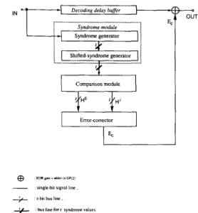
IV. HARDWARE IMPLEMENTATION A high-speed real-time decoder based on the above decoding algorithm is proposed in the following. Fig. 1 shows the functional block diagram of the decoder. The decoder comprises one syndrome gene rator, one shifted syndrome generator, one comparison module, and one error corrector. The first syndrome generator is used to
calculate the initial syndrome values of received words, Sp
(i = 1,3;.-,2t - l), that is, step 1 of the modified step-
by-step decoding algorithm. The second shifted syndrome generator is used to obtain shifted-syndrome values,
S:, S;,**-, S:-' in sequence. Both the syndrome generator and the shifted syndrome generator can be implemented by conventional LFSR's [11-[5], or by systolic circuits. The comparison module is used to calculate the temporarily changed syndrome values
si
(0 I j I n - 1; i = 1,3;..,2t - 1) and then determine the decision bits h; (0 ~j I
n - 1; p = 1,2;-., t ) . According to the decision bits, h: ( p = 1,2,.-., t ) and h; (1 s j I n - 1; p = 1,2;-.,t), the
error corrector can tell whether the first position of r J ( x ) , r n P l , is erroneous or not. If the corresponding bit is judged to be an erroneous bit, the decoder sends a cor-
recting bit E, = 1 to change its magnitude. The detailed
Decoding delay buffer
.- Syndrome generator j i Campanson module Error - c o me c t o r I 4 OUT
r-bii bur line bur line for I syndrome values
+
Fig. 1. Functional block diagram of the high-speed real-time t-error-
correcting bp BCH decoder.
design of each module of the decoder is described as
follows.
A. LFSR Syndrome Generator
It is well known that a conventional syndrome genera- tor can be implemented by t pieces of LFSR's [11-[51. A combined design of syndrome generator and shifted syn- drome generator is proposed by slightly modifying the conventional syndrome generator, as shown in Fig. 2. The circuit showed in Fig. 2 is an example of (15,7,5) bp BCH code, and the architecture can be analogously extended for any other codes. As soon as the entire r ( x ) has been
shifted into the upper LFSR's, the contents in the upper LFSR's are saved in mt pieces of latches that will be used
to reset the contents of the lower LFSR's at the (n
+
21thclock cycle by a control sequence CS1 = (1,O"-
'I:,
wheresymbol (1,O"-
'),"
denotes a periodic bit sequence having a period of n bits and having d delay bits preceding the firstbit of the bit sequence. Each of the delay bits is with a "don't-care" value, as shown in Fig. 3. After the setting,
S; can be obtained at the output. Continuously shifting
the lower LFSR n - 1 times, we can find S!, S:;.., Sr-
at the output in sequence. In Si circuit of Fig. 2, some latches are inserted between the lower LFSR and the
adders to speed up the computation of the syndrome
module. The design rule is to make the computation time less than two logic-gate delays, which is the average com- putation time of the comparison module. In S{ circuit of Fig. 2, the same number of latches are also inserted to let all the syndrome values arrive the comparison module at the same time.
The latency of the syndrome module depends on the insertion of latches, where the latency is defined as the group delay of first-input and first-output bit. For exam- ple, the latency of Fig. 2 is n
+
4.Y
.-
111-
--
111 9 3-..
m i
WE1 AND WEI: A HIGH-SPEED REAL-TIME BINARY BCH DECODER ~ 143 cso= (1,cP'): : j 1 0 0 0 e . . 0: I 0 0 0 * * e 0; 1 0 0 0
...
(a) (1.V'): . O S d < n : x-
x X 1 0 0 0 * * * 0 1 0 0 0 0 1 0 0 0 * - . 0 1 0 0 0 * - - d-bit n b mNote x means 1 can be '0' or '1'
for any control sequence (1.0" 'JP
, j , p f = d- bt delays 01 sequence 01 ii.& . where d
-
P modulo n (b)Fig. 3. Required control sequences of the real-time bp BCH decoder. (a) Global clock and basic control sequence. (b) Required control sequences.
B. Systolic Syndrome Generator
Since a feedback connection is required in an LFSR circuit, the speed of shift operation will be affected be-
cause of propagation delay of long feedback wire. In
general, the degradation in speed depends on the layout of feedback-connection wire and its length. For small m, the operation of LFSR can still be very fast. When the decoding speed is very critical, based on (5), a systolic
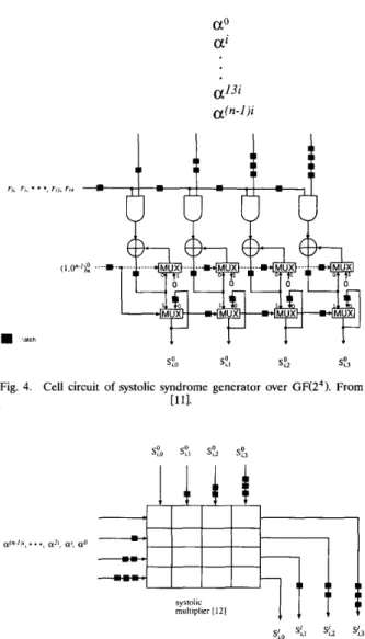
syndrome generator is presented 1111. The syndrome gen-
erator consists of t cells, where the cell circuit is redrawn
in Fig. 4. When the syndrome values are calculated in the
syndrome generator, the values will be kept there by a control sequence CS1 = (1,O"-
'1:
until the syndrome values of the next received word are calculated. Clearly, the latency of the systolic syndrome generator is n clock cycles.The shifted syndrome generator can also be imple- mented by systolic circuits. Since Sf can be further ex- pressed by
Si( a ) = rJ(x)lx=al
= mod(r(x)x'/x"
+
l } l x = , l= S p ( a ) a J ' , 0 s j I n ; i = 1,3,...,2t - 1. (10)
A cell circuit of a systolic shifted syndrome generator based on (10) is shown in Fig. 5. To perform the multipli- cation operation in GF(2"
1,
a parallel-in, parallel-out product-sum systolic multiplier can be employed, where the average computation time of a multiplication is only two gate delays[lo].
The latency of the systolic multiplieris 2m clock cycles. A shifted syndrome generator consists
of t identical cells. The shifted syndrome generator keeps
the syndrome values in the first cycle, then cyclically shifts the syndrome values once in each multiplication, that is,
obtaining Sp, S:, S,?,..., Sy- in sequence. Since some
latches are added at the output of the multiplier to let all of the bits of syndrome value arrive the output at the same time, the latency of systolic shifted syndrome gener- ator is 3m - 1 clock cycles.
a13i a(n-1)'
latch
Fig. 4. Cell circuit of systolic syndrome generator over G F e 4 ) . From
[HI.
Fig. 5. Cell circuit of systolic shifted syndrome generator.
Hereinafter, all the control sequences used in the de- coder are based on the assumption that the systolic syn- drome generator and shifted syndrome generator are em- ployed.
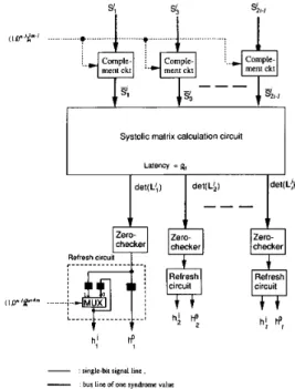
C. Comparison Module
Fig. 6 is a block diagram of a comparison module,
where t pieces of simple complement circuits are used to
pass Ss =
sp,
i = 1,3,..-,2t - 1 in parallel at the first clock cycle and then used to obtainSi
+
1 = $! for j = 1,2;--, n - 1. The operation is controlled by a control sequence CS2 = (l,O"-')~''-'. When CS2 = 1, the com-plement circuits pass the first bit of syndrome values;
when CS2 = 0, the complement circuits complement the
magnitude of the first bit of syndrome values. Fig. 7 shows
the circuit of a complement circuit. To determine the decision bits h i (0 I j I n - 1; p = 1,2;--, t ) in terms of
144 IEEE TRANSA(JI?ONS ON CIRCUITS AND SYSTEMS FOR VIDEO TECHNOLOGY, VOL. 3, NO. 2, APRIL 1993
late the values of det (LA) (0 I j 5 n - 1; p = 1,2;.-, t ) . In Fig. 6 , the matrix-calculation circuit, a subcircuit in the comparison module, is used to calculate the determinant
of the syndrome matrix, det (L;). Only addition and multi-
plication operations are required for computing the deter-
minant of the syndrome matrix. The addition operation in
GF(2") is quite simple and can be accomplished by using a set of m pieces of 2-input exclusive-oR (XOR) gates.
Since the multiplication operation is performed by a prod- uct-sum systolic multiplier with a latency of 2m clock cycles [121, the latency of the matrix-calculation circuit is determined by the number of multipliers. To reduce the overall latency of the matrix-calculation circuit, a power- sum systolic circuit can also be employed [131. The design of matrix-calculation circuits for double- and triple-error- correcting bp BCH codes will be illustrated in the later section. Finally, after finding the values of det (LA), the decision bits h; (0 I jln - 1; p = 1,2;.., t > can be deter-
mined by using t simple zero-checking circuits, each one
constructed by an m-input NOR gate and some latches, as
shown in Fig. 8. The t refresh circuits are cascaded with the zero checkers. There are two parallel outputs in the refresh circuit: the right output represents the initial decision bits, h:; while the left output pin represents the h;. The write-in operation of ho is controlled by the control sequence CS3 = (1,O"-
1)g:'4m.
/is the value h: is saved, it will be kept unchanged in the next n - 1 clock cycles. Clearly, the values appearing in the two output pins of the refresh circuit will be the same at the write cycle of h:. Finally, it is noted that the calculation of decision bitshi
for all j can be obtained by using the same - circuits, since it only depends on the circuit input,Si.
D. Error Corrector
The error corrector is used to perform the operation of
step 5 of the modified step-by-step decoding algorithm.
When the decision vectors Ho and H' are determined, the
error corrector can then determine whether the corre- sponding bit is erroneous or not in terms of the difference
between Ho and HI. The error corrector can be easily
implemented by some logic gates. After the decision, the circuit sends a correcting bit E, = 1 or E, = 0 to decode the corresponding bit. Some latches may need to be added in the error corrector to make the average computation time equal to or less than two logic-gate delays, which is the computation time in the syndrome module and com- parison module. The logic function of the error corrector is determined only by t and is independent of the block length of the code. Based on the logic function of the modified decoding algorithm, it is found that the output of
the error corrector, E,, is always equal to 0 in the writing
cycle of Ho (within this cycle, H' = Ho for any j ) . E. Operation and Control Sequences
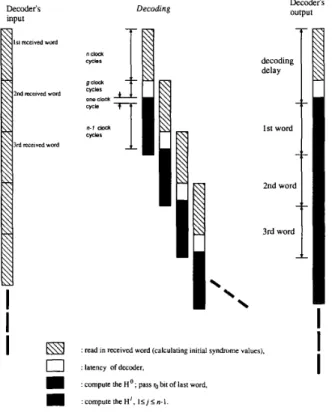
Fig. 9 shows the operation principle of the high-speed real-time decoder. The received words are consecutively read in. After n clock cycles, the initial syndrome values
Systolic matrix calculation circuit Latency =Q, det(L',) checker h: Zero- circuit h:
*,
- slngle-hl signal h e ,-
bur line of one syndrome valueFig. 6. Comoarison module I of the real-time decoder for t-error-cor-
recting bp BCH codes. I r"'- ~ ~ ~ ~ - - s _______
-
-Fig. 7. Circuit of complement circuit.
1
Fig. 8. Circuit of zero checker.
of the first received word are calculated in the syndrome generator and then passed to the shifted syndrome gener- ator, as shown in Figs. 2 and 4. At the same time, the syndrome generator is ready for calculating the initial syndrome values of next received word, that is, the second received word is consecutively read into the syndrome generator without interrupting. After g,
+
4m clock cy- cles, the decision vector Ho is obtained at the output ofWE1 AND WEI: A HIGH-SPEED REAL-TIME BINARY BCH DECODER Decoder's input IS, n c C l " e d wotd 2nd mewed word 3rd received word
Decoding Decoder's output
decoding delay
1st word
: read in received word (calculating initial syndrome values).
0
: latency of decoder,m
m
:computetheH'. I S j S n - I .: compute the Ho ; pass ro bit of last word,
Fig. 9. Operation sequence of the real-time decoder.
the comparison module. When the first ( n - 1 - gd -
4m) bits of the first received word are decoding, i.e., after 2n clock cycles of the global clock, the initial syndrome value of the second received word is found in the syn- drome generator. After the first n - :l bits of the first
received word are decoding, the Ha of the second re-
ceived word is consecutively sent to the refresh circuit of the comparison module, that is, the ro bit of the first received word is directly read out from the buffer without decoding at the cycle of finding the Ho of the second received word. Fortunately, bit ro is a check bit when the received word is in systematic form. Repeating the same process, the high-speed real-time decoder may work at a speed equal to the line-data rate, with a group delay of n
+
g+
1 clock cycles at the initial time, where g is the latency of the decoder and the extra one clock delay is used for finding Ha of the first received word.The required global-control clock signal CLKl of the
real-time decoder is shown in Fig. 3. All the shift opera-
tions of latches and registers of the decoder are controlled by the pulse lead of CLKl. In practice, the basic clock signal CLKl can be extracted from the line signal by
employing a phase-locked-loop (PLL) circuit. As shown in
Figs.1-8, the high-speed real-time decoder requires only three control sequences to do the decoding work. The first control sequence CS1 = (I, On-'): or CS1 = (1,O"-
'1;
is used to calculate the initial syndrome values and pass them to the shifted syndrome generalor. The second control sequence CS2 = (0,l"-'):"-'
is used to comple-s:
power-sum
AA
csystolic circuit [I31 E : In-Order circuit Function of
: 2m-bit delay buffer
Fig. 10. Matrix-calculation circuit of ( n , k , 5) bp BCH decoder.
Fig. 11. In-order circuit
~
145
ment the first bit of syndrome values. The third control
sequence CS3 = (1,0n-')p+4m is used to save the deci-
sion bit h:. All the three control sequences can be gener-
ated from the basic control sequence ( l , O " - ' ) ~ by some delay latches.
V. DESIGN EXAMPLES
A, Double-Error-Correcting bp BCH Codes
Fig. 10 shows the circuit diagram of a matrix calculation circuit. It needs only a power-sum circuit, which is com-
posed of m2 identical cells [13] and some in-order circuits
to control the input bit sequences [121, [131. The in-order circuit can be constructed by some latches, as shown in Fig. 11. The latency of the matrix calculation circuit is
only 2m, and the latency of the comparison circuit is
therefore equal to 3m
+
1. Fig. 12 shows the comparisonmodule of a (15,7,5) bp BCH decoder as an example. In
the fresh circuits, since the first 25 bits of (1, Oi4);: can be of any pattern, as shown in Fig. 3, the control sequence (1, Ol4):; can be substituted by (1, Oi4):, without affecting
the decoding process. For the double-error-correcting bp BCH code, +a = {(1,1)1, +1 = KO, 111, and
+*
= K0,ON.Based on the decision vectors, Fig. 13 shows the corre- sponding error corrector. The latency of the error correc- tor is only one clock cycle. Thus, considering one clock
delay of finding Ha, the decoding delay of double-error-
correcting bp BCH code can be found to be n
+
6m+
2,which is the required length of the decoding delay-buffer
MUX :
h i h:
Fig. 12. Comparison module of (15,7,5) bp BCH decoder
Fig. 13. Error corrector of (n, k , 5) bp BCH decoder.
B. Triple-Error-Correcting bp BCH Codes
From Theorem 1, the decision-vector sets of triple-er-
ror-correcting bp BCH codes are
4o
=: {(l, 1, l)), =KO,
LO},
42
= KO, 0,1)), and43
= ((1, 0, O), (O,O, 0)). The error corrector for the ( n , k, 7) bp BCH codes is imple-mented in Fig. 14 by using the decision-vector sets. The
latency of the error corrector is two clock cycles. From a
hardware-implementation point of view, the computation path in the matrix-calculation circuit should be designed carefully; a well-planned organization of computation paths will make the latency of the matrix-calculation circuit small. For example, in this case of triple-error-cor-
recting bp BCH code, computations of (let (LI), det (Li),
and det (Li) in the matrix-calculation circuit are required.
The operations of det (Li) and det (Li) are the same as
that in the double-error-correcting case. The expression
det (Li) =
(f{)6
+
(fi)33i
+
+
(Til2
can be reorga-nized as
+
+
[(f{I23i
+
s$(,
then only oneproduct-sum multiplier, three power-sum circuits, and one
adder are required to compute det (Lg). The detail of the
...
H0 H'
Fig. 14. Error corrector of (n, k , 7) bp BCH decoder.
design of a matrix-calculation circuit is illustrated in Fig. 15. It can be seen that the latency of the matrix-calcula- tion circuit is only 5m clock cycles. Thus, the decoding
delay of the triple-error-correcting bp BCH code is n
+
9m
+
3.VI. CONCLUSIONS
A modified step-by-step decoding algorithm for t-
error-correcting bp BCH codes has been presented. The decoding algorithm avoids the need to calculate the error-location polynomial in order to find the error loca-
WE1 AND WEI: A HIGH-SPEED REAL-TIME BINARY BCH DECODER 147 d e ~ 4 1 det(L:) det(LL1 .ddn m G F ( h Funclionof A 0 z m skmsni m GF(Z7 Syslollc pmduct-sum mulbplier [12]
Fig. 15. Matrix calculation circuit of ( n , k, 7) bp BCH decoder.
inverse operations, the modified decoding method can be much less complex than the conventional standard alge- braic method in hardware implementatioa. Based on the modified step-by-step decoding algorithm, a high-speed real-time bp BCH decoder has been presented. The de- coding speed of this decoder can be up to the inverse of two logic-gate delays. Based on different VLSI technolo- gies, the decoder can be operated from several hundred
megabits per second up to the order of gigabits per
second. The decoder requires only three control se- quences, which can be generated by a basic control se- quence. The detailed circuits of the matrix-calculation circuit and error-corrector of double- and triple-error-cor- recting codes are also given. Because of its simplicity in structure and circuit realization, this decoder may be easily implemented in one monolithic chip.
REFERENCES
S. Lin and D. J., Costello, Jr., Error Control ICoding. Englewood
Cliffs, NJ: Prentice-Hall, 1983.
A. M. Michelson and A. H. Levesque, Error-Control Techniques for Digital Communication. New York Wiley, 15%
W. W. Peterson and E. J. Weldon, Jr., Enor-Correcting Codes.
Cambridge, MA: M.I.T. Press, 1972.
R. E. Blahut, Theory and Practice of Error Ccaml Codes. Read-
ing, MA: Addison-Wesley, 1983.
C. C. Clark and J. B. Cain, Error Correcting Coding for Digital Communicarions. New York Plenum, 1981.
W. W. Peterson, “Encoding and error-correcting procedures for the Bose-Chaudhuri codes,” IRE Trans. Info~m. Theory, vol. IT-6,
pp. 459-470, Sept. 1960.
J. L. Massey, “Step-by-step decoding of the Bose-Chaudhuri- Hocquenghem codes,” IEEE Tmns. Inform. Xbeory, vol. IT-11, no. 4, pp. 580-585, Oct. 1965.
S. W. Wei and C. H. Wei, “High speed hardware decoder for double-error-correcting binary BCH codes,” Inst. Elec. Eng. Proc.,
vol. 136, no. 3, pp. 227-231, June 1989.
M. Kubo, I. Masuda, K. Miyata, and K. Ogiue, “Perspective on
BiCMOS VLSI’s,” IEEE J . Solid-State Circuits, vol. 23, no. 1, pp.
5-11, Feb. 1988.
H. Morkoq, “MODFET’s: Soar to 400 GHz,” IEEE Circuits De- uices Mag., vol. 7, no. 6, pp. 14-20, Nov. 1991.
C.-L. Wang and W.-J. Bair, “A VLSI architecture for implementa- tion of the decoder for binary BCH codes,” in Proc. Int. Symp. Commun., (Taiwan), Dec. 9-13, 1991, pp. 36-40.
C.-S. Yeh, Irving S. Reed, and T. K. Truong, “Systolic multipliers for finite fields GF(2m),” IEEE Trans. Comput., vol. C-33, no. 4,
pp. 357-360, Apr. 1984.
S. W. Wei, “A systolic power-sum circuit for GF(2“),” in Proc. Int. Sympos. Commun., (Taiwan), Dec. 9-13, 1991, pp. 61-64.
Shyue-Win Wei (S’85-M’86-S’88-M90) was born in Taiwan on June 9,1958. He received the
B.S. degree in telecommunications from Central
Police College, Taiwan, R.O.C., in 1980, the
M.S. degree in communications and the Ph.D.
degree in electronics from National Chiao Tung University, Hsinchu, Taiwan, in 1986 and 1990, respectively.
From 1980 to 1984 he worked at the Institute of Police Telecommunications, Taiwan. In 1990 he joined Telecommunications Laboratories. Chung-Li, Taiwan, where hd worked on the development of a high-bit: rate digital subscriber-line transmission system. Since 1992 he has been Associate Professor in the Department of Electrical Engineering, Chung Hua Polytechnic Institute. His research interests include digital trans- mission system, digital subscriber lines, coding theory, and VLSI, imple- mentation.
Che-Ho Wei (S’73-M76-M’79-SM87) was born in Taiwan in 1946. He received the B.S. and M.S. degrees in electronic engineering from Na- tional Chiao Tung University (N(=TU), Hsinchu, Taiwan, R.O.C., in 1968 and 1970, respectively, and the Ph.D. degree in electrical engineering from the University of Washington, Seattle, in 1976.
From 1976 to 1979, he was an Associate Pro- fessor at N m , where he is now a Professor in the Department of Electronics Engineering and the Institute of Electronics. From 1979 to 1982, he was the Engineering Manager of Wang Industrial Company in Taipei, Taiwan. He was the Chairman of the Department of Electronics Engineering of NCIW from 1982 to 1986 and Director of the Institute of Electronics from 1984 to 1989. He served as Associate Director of the Microelectronics and Information Science and Technology Research Center of NCTU from February to August 1990. He was on leave from the Ministry of Educa- tion and served as Director of the Advisory Office from September 1990 to July 1992.
Dr. Wei was the founding chairman of both the IEEE Circuits and Systems Society and IEEE Communication’s Society chapters in Taipei. He received the Outstanding Research Award in 1987-1989 and the Distinguished Research Award in 1990 from the National Science Coun- cil, Taiwan, R.O.C. His research interests include digital communica- tions, signal processing, and related VLSI circuits design.