國
立
交
通
大
學
資訊學院資訊學程
碩
士
論
文
車輛移動與交通號誌變換偵測系統
A Vision-based Detection System of
Vehicle Motion and Traffic Signal Transition
研 究 生:林秉聖
指導教授:莊仁輝 教授
車輛移動與交通號誌變換偵測系統
A Vision-based Detection System of
Vehicle Motion and Traffic Signal Transition
研 究 生:林秉聖 Student:Bing-Sheng Lin
指導教授:莊仁輝 Advisor:Jen-Hui Chuang
國 立 交 通 大 學
資 訊 學 院 資 訊 學 程
碩 士 論 文
A ThesisSubmitted to Institute of Computer Science and Engineering College of Computer Science
National Chiao Tung University in partial Fulfillment of the Requirements
for the Degree of Master
in
Computer Science
August 2013
Hsinchu, Taiwan, Republic of China
i
車輛移動與交通號誌變換偵測系統
研究生:林秉聖
指導教授: 莊仁輝
國立交通大學資訊學院資訊學程
摘要
一般而言,駕駛輔助系統在人們操作車輛時需要持續不斷地監測週遭環境,並從增 進交通安全與駕駛便利性的角度提供駕駛額外的資訊。從觀察中得知駕駛在長時間等待 交通號誌時經常會分心處理注意交通狀況以外的事,使得在必須起步時仍然不自覺,造 成交通堵塞或被後方以喇叭提醒。本篇研究以電腦視覺為基礎提供一偵測系統,在交通 號誌變換或前車前進時自動提醒駕駛。此系統包含三個模組:(1)以時間及空間記錄 (spatiotemporal-profile)或掃描線(scan-line)為基礎,判斷駕駛車輛是否正在前進或停止之 自身移動(ego-motion)偵測模組;(2)以 Gentle AdaBoost 為基礎來尋找可能存在的前方車 輛,並在其移動時提醒駕駛的車輛偵測模組;(3)以顏色、形狀為基礎尋找可能的號誌, 並配合背景模型在燈號轉換時發出提醒的交通號誌偵測模組。本系統希望在此較不緊急 的情況下提供人們一個減輕駕駛負擔的功能。實驗結果顯示,在白天市區的場合,本系 統在紅燈停止時能以 95.5%的查全率(recall)與 87.5%的準確率(precision),適時提醒駕駛 該再次起步以免造成交通堵塞。ii
A Vision-based Detection System of
Vehicle Motion and Traffic Signal Transition
Student: Bing-Sheng Lin
Advisor: Jen-Hui Chuang
Institute of Computer Science and Engineering
National Chiao Tung University
ABSTRACT
In general, Driving Assistance Systems continuously monitor surrounding environment, providing information to assist human driver, in order to increase safety and convenience. By observation we found when stopping at a long-waiting traffic signal, a driver may be distracted by other tasks and not focus on traffic. When it is time to go, he or she may block the traffic or be honked by the rear car for blocking the traffic, if he or she does not move. This thesis provides a vision-based detection system which reminds the driver while it is time to start moving. The system includes three modules: (1) a spatiotemporal-profile-based or scan-line-based ego-motion detection mechanism which determines whether the driver’s vehicle is moving, (2) a Gentle AdaBoost-based vehicle detector finds possible front vehicles and sends notifications once they move, and (3) a traffic signal detector based on color/shape attributes and a background model finds possible candidates and notifies the driver once the traffic signal turns green. This system tries to provide a convenient functionality that assists people in easing driving effort in such a less critical condition. Experiments show when a driver stops at a red
iii
traffic signal in day-time urban areas, this detecting system sends notifications at a recall of 95.5% and a precision of 87.5%, therefore prevents a driver from blocking the traffic.
iv
ACKNOWLEDGEMENTS
I would like to thank my advisor, Prof. Jen-Hui Chuang, who provided a free environment for me to choose such an interesting and practical research topic. During this period Prof. Chuang also encouraged me with patience to think differently, hence in the system a novel scan-line-based ego-motion detector with excellent performance was created.
Especially I would like to thank Dr. Hua-Tsung Chen who helped a lot in completing this thesis. From Dr. Chen I learned the rigorous spirit in scientific essay writing. Also with careful chosen vocabulary and expressions, it is easier to correctly transfer the concept and context behind the idea.
Lastly I want to thank my family who support me to accomplish this master degree. Now I can confidently face future challenges without past concerns in my mind.
v
CONTENTS
摘要 i ABSTRACT ... ii ACKNOWLEDGEMENTS ... iv CONTENTS ... v LIST OF FIGURES ... viLIST OF TABLES ... viii
LIST OF SYMBOLS ... ix
Chapter 1. Introduction... 1
1.1 Motivation... 1
1.2 Review of Related Works ... 1
1.3 Overview of Proposed Methods ... 3
1.4 Thesis Organization ... 5
Chapter 2. System Architecture... 6
2.1 Timing to issue a T2G notification ... 6
2.2 The Finite State Machine ... 7
2.3 Ego-Motion Detector (EMD) ... 8
2.3.1 Spatiotemporal-profile-based Approach (SpT) ... 8
2.3.2 Scan-line-based Approach (SL) ... 11
2.4 Vehicle Detector (VD) ... 13
2.5 Traffic Signal Detector (TSD) ... 16
Chapter 3. Experiment Results ... 20
3.1 Data Collection and Ground Truth Generating ... 20
3.2 Performance of Ego-Motion Detector ... 22
3.3 Performance of Vehicle Detector and Traffic Signal Detector ... 25
3.4 Performance of the Time2Go System... 29
3.5 Supplemental Information ... 31
Chapter 4. Conclusions and Future Works ... 32 References 33
vi
LIST OF FIGURES
Figure 1. Flowchart of the Time2Go System ... 4
Figure 2. Landscape type (left) and portrait type (right) traffic signals ... 6
Figure 3. The finite state machine maintained in the system ... 7
Figure 4. Mask w(x, y) ... 9
Figure 5. Different patterns of spatiotemporal image T(x, t) (a) Moving forward and then turning right (b) Turning right, slowing down and then stopped ... 9
Figure 6. Gray image (top), spatiotemporal image (middle) and StdDev (bottom). (a) An ego-moving condition (b) A full-stop condition (c) Vertical stripes at the middle of spatiotemporal image indicates a temporary stop or passing through an open-sky area. ... 10
Figure 7. Scan-lines arranged as a fan shape. Green- (red-) colored feature points and scan-lines represent forward (backward) moving direction. The vanishing point in yellow color is manually set. ... 11
Figure 8. List of statuses of scan-lines and the legends. ... 12
Figure 9. Histogram of Orientation Gradient (a) An HOG detection window and its structure (b) A bicycle and its HOG feature ... 14
Figure 10. Some false alarms of AdaBoost vehicle classifier ... 15
Figure 11. Procedures used in Vehicle Detector ... 15
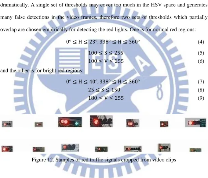
Figure 12. Samples of red traffic signals cropped from video clips ... 17
Figure 13. Glare reduction (a) A red signal with glare (b) The red light and the glare (c) After removing the glare ... 18
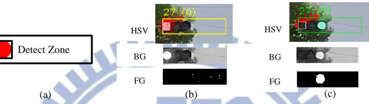
Figure 14. Traffic Signal Detector (a) A Detect Zone aligns and surrounds a good red candidate. (b) Detect Zone #27 and the BG/FG of Sigma-Delta BG Model. 0 hits of green regions. (c) Detect Zone #27 has 5 hits and a red-green transition is found. ... 18
Figure 15. Route of collecting dataset in Taipei City. Recorded by Google My Tracks. ... 21
Figure 16. Samples for Vehicle Detector training ... 21
Figure 17. Definitions for EMD performance. (TP = True Positive, FP = False Positive, FN = False Negative, ST = STOPPED, M = MOVING) ... 22
Figure 18. Conditions for the Ego-Motion Detector to behave incorrectly (a) Passing an open sky area (b) A high-height vehicle comes and stops nearby after cool-down is completed. ... 24
Figure 19. User interface of Time2Go System ... 25 Figure 20. Examples of VD detections (a) A false vehicle detection (b) Skew rear view (c) A
vii
detection ... 28 Figure 21. Examples of incorrect TSD detections (a) A bus triggers a Detection Zone (b) A
neon board forms a Detection Zone and triggers (c) Background with red-like color (d) Flickering effect of a bus LED sign board (e) A true positive detection 28
viii
LIST OF TABLES
Table 1. Timing to issue notification ... 7
Table 2. Part of statistics of the dataset used in this thesis ... 21
Table 3. Performance of Ego-Motion Detectors ... 23
Table 4. Parameter of Ego-Motion Detectors (EMD) ... 24
Table 5. Parameters of Vehicle Detector (VD) and Traffic Signal Detector (TSD) ... 26
Table 6. Performance of Vehicle Detector (VD) and Traffic Signal Detector (TSD)... 27
Table 7. Performance of the Time2Go System ... 29
ix
LIST OF SYMBOLS
Dcd Cool-down duration for EMD
Err1 Error tolerance earlier than a ground truth
Err2 Error tolerance later than a ground truth
ErrM1 Error tolerance earlier than a MOVING ground truth
ErrM2 Error tolerance later than a MOVING ground truth
ErrST Error tolerance for a STOPPED ground truth
HDZ Expansion factor of height for a Detect Zone
ISD Lower bound of standard deviation
Lseg Lower bound of consecutive pixels
Mgr Lower bound of consecutive frames for green regions
Mov Upper bound of time for a Detect Zone to be ready
Mred Lower bound of consecutive frames for red regions
MSL Lower bound for a scan-line to report movement
Mv Lower bound of consecutive frames to report T2G
Pdark Lower bound of % for dark pixels in a red region
Pfg Lower bound of % of foreground pixels
Pgr Lower bound of % for green pixels in a foreground region
Rneighbor Search range in a scan-line
Pred Lower bound of % for a red region to be overlapped
Ssmaller Lower bound of % for size comparison of red regions
Slarger Upper bound of % for size comparison of red regions
SSL Lower bound of speed of feature points
Vdark Upper bound of intensity value for dark pixels
1
Chapter 1. Introduction
1.1 Motivation
For typical driving experience in the urban areas in Taiwan, there is a high possibility that a driver need to stop at the traffic signals for more than 60 seconds. If a driver is distracted from the waiting for the traffic signal to turn green, e.g., for tuning for a radio program or finding accessories in the purse, he or she is very likely to miss the traffic signal transition, or be honked by the rear vehicle for blocking the traffic. We want to develop a detecting system which starts to monitor traffic signals and vehicles when the driver stops at a red traffic light, and notifies the driver when it is time to move again.
As car video recorders become popular, more and more people attach these devices to the windshield or on the dashboard to record their journeys. Compared to the radar or laser solutions, camera-based solutions are more accessible. Many brands of car video recorders, ranging from NTD 3,000 to NTD 10,000, can be easily bought. Furthermore, considering the computation power of mobile devices today, e.g., HTC One X with 1.5 GHz quad-core CPU (2012), car video recorders with more powerful computing capabilities are also expectable. Therefore, we choose vision-based approach to detect traffic events and issue timely notifications to the driver.
1.2 Review of Related Works
While driving on the roads, the traffic conditions may change rapidly. Besides controlling the vehicle, a driver has to continuously attend to and react immediately and properly to receive visual and acoustic information around the vehicle. However, humans may not maintain a high level of concentration for a prolonged period of time, nor has automatic vehicle driving not been mature, the development about Driver Assistance Systems (DAS) [1] becomes an
2
important research field. A DAS monitors surrounding environment continuously by sensors and provides extra information to the driver. Besides assisting the driver, some DAS technologies can be the foundations of autonomous driving in the future.
Categorized by applications, many technologies [2] have been developed for DAS which include: lane departure warning system [3] [4], adaptive cruise control [5], collision avoidance system [6], pedestrian protection system [7] blind spot detection [8], driver drowsiness detection [9], automatic parking [10], traffic sign recognition [11] [12] [13], etc. Some of these technologies have also been commercialized. For example, Volvo’s City Safety [14] can prevent collision at speed under 50 km/h by using an active sensor to scan the region 10 meters in front of the vehicle, and will apply brake if the driver is not aware of the obstacle.
While most DAS technologies attempt to increase car safety by informing the driver immediately when the system detects a possible danger, others, such as automatic parking and traffic sign recognition intent to provide useful and convenient functionalities to ease the driving effort. This thesis will concentrate on the convenience point of view.
As described previously we plan to design a system to notify a driver stopped by the traffic signal or stopping vehicles in front when to start moving again. In general, whether a notification should be issued will be determined by the transition of traffic signals as well as the behavior of front vehicles. Color and shape are important features for detecting traffic signals. Park and Jeong [15] find traffic signal regions by thresholding RGB values, applying circularity check and rejecting candidates which do not last long enough. Gonzâles et al. [13] use Hough transform and aspect ratio to extract possible traffic sign locations. Meanwhile, multi-frame validation is proved to be effective to reject unstable candidates.
As for vehicle detection, Zheng and Liang [16] train classifiers by using RealBoost [17] with edge-like stripe features and deal multi-view problem with Cluster Boosting Tree [18] algorithm. Kuo and Nevatia [19] detect multi-view vehicles with a tree structure detector in
3
which each node is a Gentle AdaBoost classifier [17] based on HOG feature [20]. Chen and Lin [21] identify vehicles at night by analyzing candidates of brake light regions in the frequency domain. Jazayeri et al. [22] represent the movement of vehicles in a spatiotemporal image constructed by horizontal edges. To the best of our knowledge, there are no studies about detecting the transitions of traffic signals, which motivates the proposed approach.
1.3 Overview of Proposed Methods
In this thesis, we design an innovative and practical daytime DAS system, entitled
Time2Go, which is capable of reminding the driver when it is time to drive forward by analyzing
the video clips captured by a car video recorder. Fig. 1 illustrates the flowchart of the Time2Go System which is initiated whenever a video frame is captured. After it is converted to HSV space the frame is then sent to different modules in the system depending on the driver is moving on the road (state MOVING) or stopping at the traffic signal (state STOPPED), as determined by the Ego-Motion Detector. (Both a spatiotemporal-profile-based method [22] and a scan-line-based method will be considered for the Ego-Motion Detector in this thesis.)
If the system determines that driver’s vehicle is stopped, video frames will be sent to the Vehicle Detector and the Traffic Signal Detector in an interleaving way. The Vehicle Detector finds the locations and motions of front vehicles based on Gentle AdaBoost [17] and HOG features [20]. The performance is further improved with a red-region-pair checking. The Traffic Signal Detector is used to locate the candidates of traffic signals, and sends out a notification when a red-to-green happens. The concept of multi-frame validation is widely used in all three modules.
4
No RGB to HSV conversion
Set state MOVING
Ego-Motion Detector Set state MOVING Set state STOPPED User exits or no more frame? End Ego-motions? Start Yes No Yes
Vehicle Detector Traffic Signal Detector Frame number Vehicle status? Signal status? Even Odd Moving Stay still or no vehicle found Red or no signal found Green Send Time2Go notification Figure 1. Flowchart of the Time2Go System
5
1.4 Thesis Organization
The remainder of this thesis is organized as follows. Chapter 2 elaborates the detail of each modules of the proposed DAS system, including Ego-Motion Detector, Vehicle Detector and Traffic Signal Detector. Dataset collection, experiment results and assessment of system performance are described in Chapter 3. Finally, conclusions and future works of this thesis are given in Chapter 4.
6
Chapter 2. System Architecture
The purpose of the Time2Go system is providing a notification, T2G, to signal the driver it is time to start moving when stopping at a traffic signal. However, it is still the driver’s responsibility to decide if it is actually a safe timing to move, in case of any vehicle or pedestrian charging into the way suddenly. In the following sections, we will describe when the T2G notification will be issued and the design concept of the whole system.
2.1 Timing to issue a T2G notification
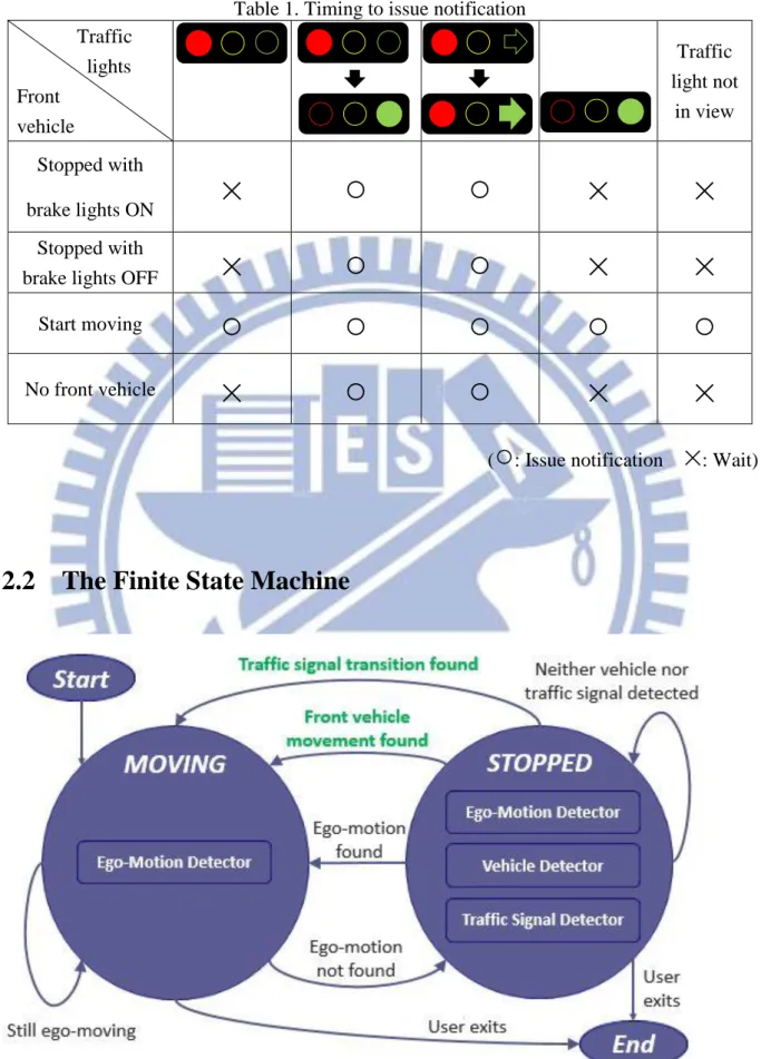
Table 1 shows the timing when a driver should concentrate back on the driving when stopping at a red traffic signal. One can see that the timing to notify is when the green signal is turned ON while the red signal turns OFF, or when a green signal shows up near a red signal (i.e. a right-turn signal), or when the front vehicle, if exists, starts moving.
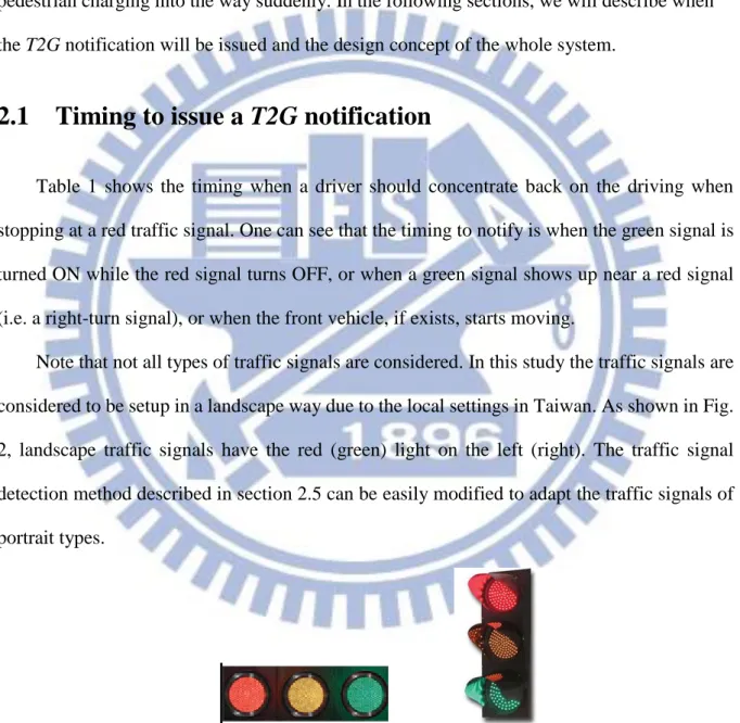
Note that not all types of traffic signals are considered. In this study the traffic signals are considered to be setup in a landscape way due to the local settings in Taiwan. As shown in Fig. 2, landscape traffic signals have the red (green) light on the left (right). The traffic signal detection method described in section 2.5 can be easily modified to adapt the traffic signals of portrait types.
7
Table 1. Timing to issue notification Traffic lights Front vehicle R Traffic light not in view Stopped with brake lights ON
×
○
○
×
×
Stopped withbrake lights OFF
×
○
○
×
×
Start moving
○
○
○
○
○
No front vehicle
×
○
○
×
×
(
○
: Issue notification×
: Wait)2.2 The Finite State Machine
8
According to the above rules, the Time2Go System maintains a finite state machine which consists two states: MOVING and STOPPED, as shown in Fig. 3. Ego-Motion Detector (EMD) is enabled in both states and processes every frame to decide if the driver’s vehicle is moving or not. When it is in STOPPED state, Vehicle Detector (VD) and Traffic Signal Detector (TSD) are enabled. Frames are sent to the two modules alternatively to ease CPU loading. The system sends notifications only when VD detects front vehicle movements or TSD detects traffic signal transitions (shown in green in Fig. 3) as described earlier in section 2.1.
2.3 Ego-Motion Detector (EMD)
In this thesis two methods are studied and compared for their effectiveness in determining the status of ego-motion. The spatiotemporal-profile-based approach is inspired by the method for detecting vehicle locations in [22]. Various stripe patterns can be used to distinguish between moving and stopped. In addition, a scan-line-based approach which calculates the moving speed of feature points in video frames along scan lines originated from the vanishing point of the road.
2.3.1 Spatiotemporal-profile-based Approach (SpT)
Referring to the method used in [22] to detect vehicle positions, the approach will find (i) horizontal edges Et (x, y) of a frame t, (ii) apply a mask w(x, y) on Et (x, y) to focus on the region
of interest, and (iii) vertically project the masked ROI onto a spatiotemporal image T(x, t) with
/2 2 / ) , , ( ) , ( ) , ( h h y t y x E y x w t x T (1)where h is the height of spatiotemporal image. T(x, t) can be seen as a profile of horizontal edges along the time axis of consecutive frames.
9
signs provide enough information to generate distinctive profiles. In this thesis, the mask w(x,
y) is set to focus on the upper portion of video frame, as shown in Fig. 4, to avoid interference
of relative motions of nearby vehicles. The height of spatiotemporal image provides a temporal buffer when the vehicle is temporarily stopped or passing an open sky area (Fig. 6c). This buffer also means a cool-down duration (Dcd) before the finite state machine going to STOPPED state.
In urban area, a buffer of 300 frames (about 10 seconds) is considered to be a reasonable time window.
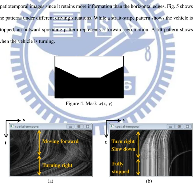
Instead of horizontal edges in [22], we extract edges of all directions in frames to form spatiotemporal images since it retains more information than the horizontal edges. Fig. 5 shows the patterns under different driving situations. While a strait-stripe pattern shows the vehicle is stopped, an outward spreading pattern represents a forward ego-motion. A tilt pattern shows when the vehicle is turning.
x t Turning right Moving forward x t Fully stopped Turn right Slow down (a) (b)
Figure 5. Different patterns of spatiotemporal image T(x, t) (a) Moving forward and then turning right (b) Turning right, slowing down and then stopped
10
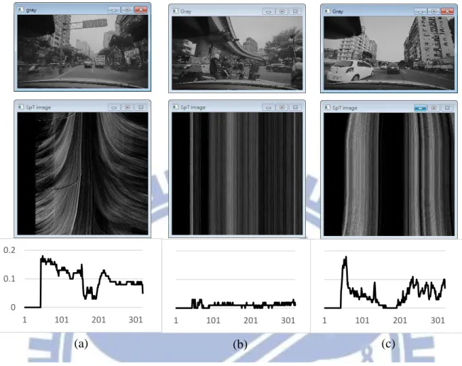
To describe if the driver is ego-moving, standard deviation of each column in T(x, t) is used to describe the vertical homogeneity of profile, as shown in the bottom row of Fig. 6.
𝜇𝑡(𝑥) =1ℎ∑ℎ 𝑇(𝑥, 𝑡)
𝑡=1 (2)
𝜎𝑡(𝑥) = √1ℎ∑ℎ𝑡=1(𝑇(𝑥, 𝑡) − 𝜇𝑡(𝑥))2 (3)
When there is an ego-motion, continuous high standard deviation values appear in σt (x) as
shown in the bottom charts of Fig. 6. A simple mechanism searches for the existence of segments using a threshold ISD for the values of σt (x) and a threshold Lseg for the length of
segments, and thus distinguishes between the states of moving and stopping.
Figure 6. Gray image (top), spatiotemporal image (middle) and StdDev (bottom). (a) An ego-moving condition (b) A full-stop condition (c) Vertical stripes at the middle of spatiotemporal image indicates a temporary stop or passing through an open-sky area.
0 0.1 0.2
1 101 201 301 1 101 201 301 1 101 201 301
11
2.3.2 Scan-line-based Approach (SL)
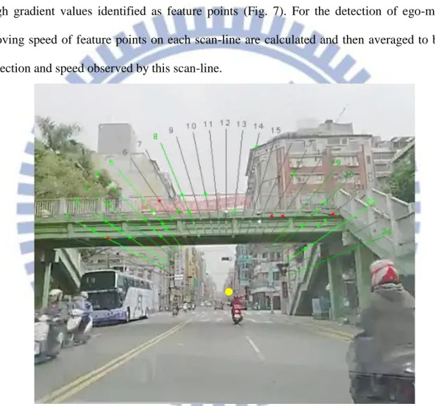
For a forward looking video recorder, objects in the video will spread outward from the vanishing point of the road as the vehicle is moving forward along a straight road. Therefore we can design a method to track feature points in 1D space (i.e. a scan-line) rather than in 2D space (video frame), to save much computation time. Gradients of pixels are calculated, with high gradient values identified as feature points (Fig. 7). For the detection of ego-motion, moving speed of feature points on each scan-line are calculated and then averaged to be the direction and speed observed by this scan-line.
Figure 7. Scan-lines arranged as a fan shape. Green- (red-) colored feature points and scan-lines represent forward (backward) moving direction. The vanishing point in yellow color is manually set.
In general, as the vehicle moves forward, feature points should move outward along the scan line. For each scan-line, the scan-line-based algorithm compares the same scan-line in the previous frame, and searches for a nearest neighbor for each feature point in a predefined range
12
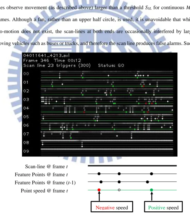
Rneighbor. The distance between these two neighbor feature points is used as the moving speed
(in pixels/frame) of this point, and the average speed of these points defines how fast and which direction the scan-line observes ego-motion. E.g., as shown in Fig. 8, scan-line #1 on the left has two feature points. The green one is a forward moving point and the red one is backward moving. The scan-line is green-colored due to the average of the two points is still positive.
To filter noises, this fan is designed to report ego-moving only when more than one scan-lines observe movement (as described above) larger than a threshold SSL for continuous MSL
frames. Although a fan, rather than an upper half circle, is used, it is unavoidable that while ego-motion does not exist, the scan-lines at both ends are occasionally interfered by large moving vehicles such as buses or trucks, and therefore the scan line produces false alarms. Such
Figure 8. List of statuses of scan-lines and the legends.
Negative speed Positive speed
Scan-line @ frame t Feature Points @ frame t Feature Points @ frame (t-1)
13
false alarms can be reduced heuristically by confirming if both leftmost and rightmost scan-lines agree or not. The fan reports stopped only after a cool-down duration Dcd of 300 frames
(about 10 sec), as same as in the spatiotemporal profile.
2.4 Vehicle Detector (VD)
To detect the vehicles in front of the driver, a Gentle AdaBoost [17] classifier cascade using Histogram of Oriented Gradients (HOG) features [20] is trained. AdaBoost [23] is an iterative process to train a strong classifier by adding weak classifiers in each turn, until a predetermined number of weak classifiers are found or a target accuracy is met. In each iteration the training process re-weights samples to focus on those misclassified in the last iteration.
Real AdaBoost [24] and Gentle AdaBoost are two of the several variants of AdaBoost. Unlike the weak classifiers which output discrete values {-1, 1} in AdaBoost, weak classifiers of Real AdaBoost output real values between [0, 1]. This value is a probability that an input sample belongs to a class, under current weight distribution of the training samples. Real AdaBoost performs exact optimization on each weak classifier Hm(x). Gentle AdaBoost further
improves it by using Newton stepping and provides a more stable ensemble that outperforms
Algorithm 1. Gentle AdaBoost
Input: 𝑍 ≔ {𝑧1, 𝑧2, … , 𝑧𝑁, }, 𝑧𝑖 ≔ (𝑥𝑖, 𝑦𝑖), the training set
M, a maximum number of weak classifiers
Output: 𝑠𝑖𝑔𝑛(𝐻(𝑥)), a strong classifier for the training set Z
1. Initialize weights 𝑤𝑖 ← 1 𝑁⁄ , 𝑖 ≔ {1,2, … , 𝑁} 2. for m = 1 to M do
3. Fit the regression function ℎ𝑚(𝑥) by weighted least square 𝑦𝑖 to 𝑥𝑖 with 𝑤𝑖 4. Update 𝐻(𝑥) ← 𝐻(𝑥) + ℎ𝑚(𝑥)
5. Update 𝑤𝑖 ← 𝑤𝑖𝑒𝑥𝑝(−𝑦𝑖ℎ𝑚(𝑥𝑖)) and renormalize 6. end
14
Real AdaBoost. Algorithm 1 shows how Gentle AdaBoost works.
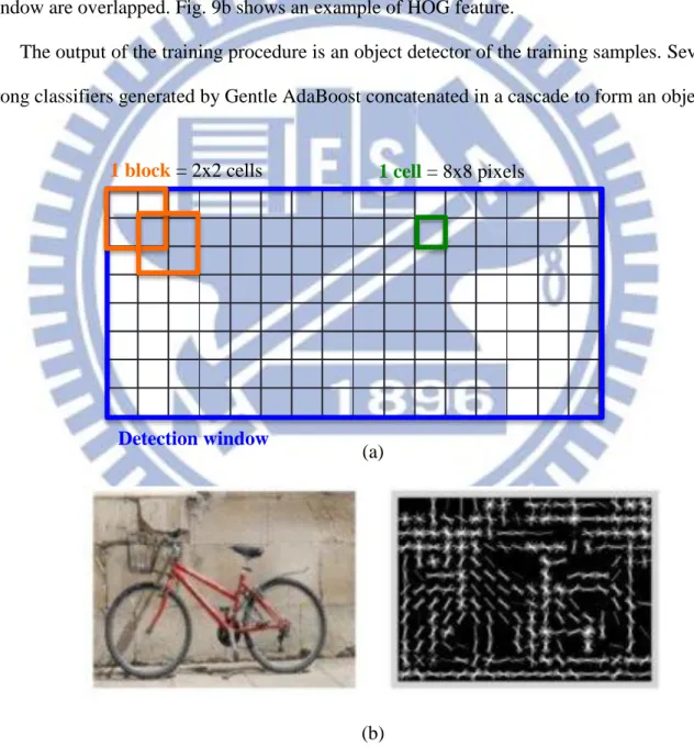
HOG is based on the idea that object appearance can be described by the distribution of intensity gradients. An HOG detection window (Fig. 9a) scans all over the input image to find expected objects. The window is divided into cells of 8x8 pixels. For each pixel in the cell, the magnitude and orientation of gradients are calculated and stored in a histogram. Each HOG descriptor is a block consisting 2x2 cells (i.e. 4 histograms), and the positions of blocks in the window are overlapped. Fig. 9b shows an example of HOG feature.
The output of the training procedure is an object detector of the training samples. Several strong classifiers generated by Gentle AdaBoost concatenated in a cascade to form an object
(a)
(b)
Figure 9. Histogram of Orientation Gradient (a) An HOG detection window and its structure (b) A bicycle and its HOG feature
1 block = 2x2 cells 1 cell = 8x8 pixels
15
detector. We trained the detector by using OpenCV 2.4. At the training stage, a target false alarm rate of each level, and a maximum number of levels should be set as parameters to be the stopping criteria. Although we set the target false alarm rate of each level with 0.4, and the false alarm rate of the whole cascade is 0.4 13 = 6.71 10-6 after 13 levels were generated, it is still
too high when comparing to the total number of detections, i.e. the number of detection windows in a single frame, multiplied by the number of frames in a video. Some false positive
(a) Apply trained HOG detection cascade on each frame
(e) Apply a Sigma-Delta
background model
(f) A vehicle is moving if the % of foreground pixels is above a threshold and lasts long enough.
(d) Focus on 2/9 of center area where includes car plate and excludes braking lights
(b) A “stable” candidate should be detected twice and regions overlap over 80%.
(c) A “good” candidate should have a red region pair in both left and right 1/3 region.
dt+1
dt
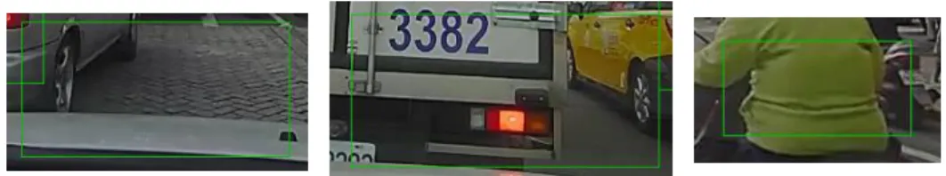
Figure 10. Some false alarms of AdaBoost vehicle classifier
16
examples are shown in Fig. 10. To increase the precision of Vehicle Detector, two techniques are applied as shown in Fig. 11b and 11c. First, a detected candidate dt in frame t is confirmed
to be a “stable” one only when there is another detection dt+1 in frame (t + 1), and dt+1 overlaps
dt over 80% in area (Fig. 11b). Second, since we are searching for the rear view of vehicles, the
braking light pair is a good clue to reject false alarms. A “stable” candidate is recognized as a “good” one only if two red regions are identified in the left 1/3 and right 1/3 of the detecting window (Fig. 11c). The technique of finding red regions is the same as in Traffic Signal Detector (section 2.5).
Once good vehicle candidates are found, the next step is to determine when the vehicle moves. A Sigma-Delta Background Model [25] is applied on each good candidate for motion detection. The background model is applied only on the center-bottom area of detection window, for the reasons that the license plate provides rich textures, also the luminance changes of both break lights and the center brake lamp are avoided (Fig. 11d & 11e). The front vehicle is recognized as moving if the percentage of foreground pixels is over Pfg % for consecutive Mv
frames (Fig. 11f), and the Vehicle Detector issues a T2G notification.
2.5 Traffic Signal Detector (TSD)
Another source indicating the timing of start moving comes from the traffic signals. The idea behind traffic transition detection is to find a status change when a green signal appears near the location of a red signal. Compared to other methods which locate static traffic signals in a video, the detection of dynamic transition from red to green can be benefitted by utilizing background estimation. The background model allows us to generate more red regions with loosen thresholds regardless of the quantity of false positives, because fewer candidates are able to change brightness over time. To determine thresholds such as colors, area, width-height ratio, bounding box dimension for traffic signals, we cropped 228 traffic signal images from the
17
testing video dataset for training (Fig. 12).
A red signal finding procedure in HSV color space is the first step for finding traffic signal candidates. Due to the high luminance of LED traffic signals, different view angles to the LEDs, as well as the auto white balance and auto gain control of the car video recorder, we found the hue value of red traffic signals may range from red to orange, also saturation values vary dramatically. A single set of thresholds may cover too much in the HSV space and generates many false detections in the video frames, therefore two sets of thresholds which partially overlap are chosen empirically for detecting the red lights. One is for normal red regions:
0° ≤ H ≤ 23°, 338° ≤ H ≤ 360° (4)
100 ≤ S ≤ 255 (5)
100 ≤ V ≤ 255 (6)
and the other is for bright red regions:
0° ≤ H ≤ 40°, 338° ≤ H ≤ 360° (7)
25 ≤ S ≤ 150 (8)
180 ≤ V ≤ 255 (9)
Figure 12. Samples of red traffic signals cropped from video clips
Next we reject regions with improper shapes and sizes. Separated regions are identified by a region growing process and attributes of each region including area, bounding box, width-height ratio are calculated as well. The traffic signal detection proposed in [15] also introduces a circularity check for identifying red lights. However, it is not considered in this thesis due to lens distortion, perspective distortion, and occlusion all make circularity impractical. Only regions with proper range of region sizes, width-height ratios, bounding box size are chosen for
18
later process. Further, to get more precise regions of red lights with glares, regions marked as normal red (darker gray region in Fig. 13b) are removed if they are surrounded a bright red region (light gray region in Fig. 13b). The result here are refined regions of the red lights.
Multi-frame validation is then applied to detect stable red light candidates. The red signal detecting procedure starts from the time entering STOPPED state. To be recognized as a good candidate, each red region should be overlapped by the later regions for over Pred % and Mred
times. The size range of the later regions should also between Ssmaller (< 1) and Slarger (> 1) times
of the candidate. This detecting procedure is expected to complete within Mov frames, otherwise
this candidate is considered to be a blinking light such as a neon signboard and discarded. The intensity of traffic lights changes as time goes by, which is a good property to differentiate from other objects. For each good red region candidate, a larger Detect Zone of predefined scale, WDZ times wider and HDZ times higher, is created. This scale ensures both the
widest traffic signal and slightly tilt traffic signals can be included (Fig. 14a). Each Detect Zone Detect Zone HSV BG FG HSV BG FG (a) (b) (c) (a) (b) (c)
Figure 13. Glare reduction (a) A red signal with glare (b) The red light and the glare (c) After removing the glare
Figure 14. Traffic Signal Detector (a) A Detect Zone aligns and surrounds a good red candidate. (b) Detect Zone #27 and the BG/FG of Sigma-Delta BG Model. 0 hits of green regions. (c) Detect Zone #27 has 5 hits and a red-green transition is found.
19
is actually a Sigma-Detla Background Model (Fig. 14b). By introducing a background model we further reduce the data size from the whole frame to a small bounding box, and thus the thresholds of green colors can be loosen. The thresholds below are determined subjectively to include all light green colors:
100° ≤ H ≤ 200° (10)
3 ≤ S ≤ 255 (11)
70 ≤ V ≤ 255 (12)
One more characteristic helps reduce false detection. Since traffic signals are visually darker when no light is shown, the average luminance value of the darker pixels (V < Vdark,
excluding the red region and sky area) inside the Detect Zone, should be lower than the average luminance of the red region. Also the number of dark pixels should be at least Pdark % of the
red pixels. A low value of 30% is chosen for Pdark because the number of dark and red pixels
vary dramatically due to glare or different viewing angles.
Next we determine when the traffic signal turns green and the following two characteristics describe this behavior well. First, foreground pixels in the BG model imply luminance change. Second, if there are more than Pgr % of foreground pixels are green, and this situation lasts for
Mgr frames, these pixels are eligible to be a stable light green region. A Detect Zone recognizes
that the green signal is stably ON after Mgr consecutive counts is accumulated, otherwise the
counter is reset. The Traffic Signal Detector then issues a T2G notification if any Detection Zone finds a stable ON green region.
20
Chapter 3. Experiment Results
3.1 Data Collection and Ground Truth Generating
To evaluate the system performance a new dataset is created by collecting the videos captured by Vosonic V737W car video recorder (1280 x 720 at 29.97 fps, RGB format). We drive around Taipei City (Fig. 15) in cloud and sunny day times. The total distance is 155.6 KM, and 9 hours 7 mins is spent. The raw video files are cut into short clips containing about 10 seconds before the driver stops and 10 seconds after the traffic signal transition or front vehicle movement. All timings (in seconds) when the driver stops, the front vehicle starts moving, and the traffic signal turns from red to green are manually recorded as ground truths. There are total 223 stop-then-go video clips created. Besides video clips, 197 images of rear views of sedans are cropped from the video frames for vehicle detector training (Fig. 16).
Table 2 shows part of the statistics of testing dataset we created. According to the table, when stopped, there is a 100% probability that a vehicle or a traffic signal is in camera view. There is a 96.1% probability that a front vehicle exists or the traffic signal is large enough (≥ 4x4) for the system to identify. These are the reasons showing automatic vision-based detection is feasible.
21
Figure 15. Route of collecting dataset in Taipei City. Recorded by Google My Tracks.
Figure 16. Samples for Vehicle Detector training
22
3.2 Performance of Ego-Motion Detector
To test both performances of the spatiotemporal-profile-based (SpT) and the scan-line-based (SL) Ego-Motion Detector, all 9 hrs and 7 mins video files are used for evaluation. We separately evaluate recall and precision of the timestamps when the detector reports STOPPED and MOVING. Note that the total number of reported detections may be different from the number of ground truths. For example, when each time the driver’s vehicle is stopped, the detector may incorrectly report an extra false MOVING, due to certain unwanted reasons before the driver really starts moving, and then reports another extra false STOPPED after the cool-down is finished again.
Fig. 17 below shows how the statistic indices in this thesis are defined. Note that the timestamps are compared in frames. The detected STOPPED time TST_det should fall in the range
between (TST_gt – ErrST) and (TST_gt + Dcd+ ErrST) to be a true positive, where TST_gt is the ground
truth of STOPPED time, Dcd is the cool-down duration for passing by an open-sky area, and
ErrST is a tolerance limit. The detected MOVING time TM_det should fall in the range between
(TM_gt – ErrM1) and (TM_gt + ErrM2) to be a true positive, where TM_gt is the ground truth of
MOVING time, ErrM1 and ErrM2 are the tolerance limits.
We consider 300 frames (about 10 seconds at 29.97 FPS) to be a reasonable value for the cool-down duration Dcd of the Ego-Motion Detector in urban region. ErrST is set to 30 frames
due to the ground truths are manually recorded in a time resolution of seconds, and the frame rate is 29.97 fps. ErrM1 is also set to 30 frames for the same reason. ErrM2 is considered to be
TPST TPM TST_det TM_det Ground truth TST_gt TM_gt t Detector t FPST FPM TPST FPM FPST TPM FNST FNM
Figure 17. Definitions for EMD performance. (TP = True Positive, FP = False Positive, FN = False Negative, ST = STOPPED, M = MOVING)
23
Table 3. Performance of Ego-Motion Detectors
Spatiotemporal-based (SpT) Scan-line-based (SL) STOPPED MOVING STOPPED MOVING Recall 91.9% 90.7% 91.7% 90.8% Precision 74.3% 63.3% 92.3% 82.5% Avg. proc.
time
Original: 84.8 ms/frame
1/16 size: 8.3 ms/frame 0.14 ms/frame
less critical since the main purpose of the EMD is to enable (from MOVING to STOPPED) the other two modules, but not to disable (from STOPPED to MOVING) them. We set it to 90 frames regarding the starting movement may be slow and difficult to be detected.
Table 3 shows the performance of both methods. For the SpT method, video frames are scaled down to 1/16 of the original size to achieve real-time (over 30 FPS), saving time for the other two modules to work simultaneously in the state STOPPED. For the SL method, original 720p frames are used. Both methods show excellent recall rate of over 90%. This means when the driver stops or moves, EMD is highly possible to be triggered. For both methods the only the reason of not detecting a stop (i.e. a false negative) in this experiment is that the period of stop is shorter than the EMD cool-down duration, therefore before the detector reports STOPPED ego-motion starts again.
From the perspective of precision, the SL method does better than the SpT method at both reporting STOPPED and MOVING. Nearly all false alarms of STOPPED-MOVING pairs by the SL method are due to slow ego-motion at an open sky area such as driving near a traffic circle (Fig. 18a), where textures in the sky are not rich enough to leave patterns on the spatiotemporal image. Another condition of false MOVINGs is when the driver starts slowly, tiny relative motions of objects in the background trigger the SL-based EMD late. The SpT
24
method suffers from the same reasons. Besides, the SpT method does not tell relative forward motions from backward ones. This results in false alarms when buses or trucks (i) come and stop at the traffic signal later than the driver (Fig. 18b), (ii) pass by at the opposite lane, or (iii) stop in front of the driver. In such situations buses/trucks are possible to enter the region of sky mask w(x, y) so that SpT-based EMD may incorrectly recognizes as MOVING. This explains
why the precision of SpT is much lower than the precision of SL. For the performance and computing cost reasons, we choose the SL method as the Ego-Motion Detector to integrate with the other two modules. Parameters used in this experiments are shown in Table 4.
Table 4. Parameter of Ego-Motion Detectors (EMD)
Modules Param. Value Description
SpT ISD 100 Lower bound (L.B.) of standard deviation
Lseg 15 pixels L.B. of consecutive pixels
SL
Rneighbor 20 pixels Search range in a scan-line
SSL 0.2 pixel/frame L.B. of speed of feature points
MSL 5 frames L.B. for a scan-line to report movement
Performance
Dcd 300 frames Cool-down duration for EMD
ErrST 30 frames Error tolerance for a STOPPED ground truth
ErrM1 30 frames Error tolerance earlier than a MOVING ground
truth
ErrM2 90 frames Error tolerance later than a MOVING ground
truth
(a) (b)
Figure 18. Conditions for the Ego-Motion Detector to behave incorrectly (a) Passing an open sky area (b) A high-height vehicle comes and stops nearby after cool-down is completed.
25
3.3 Performance of Vehicle Detector and Traffic Signal Detector
Figure 19. User interface of Time2Go System
Next we test if VD and TSD issue T2G notification on time. Fig. 19 illustrates the user interface. The white-colored text at the center bottom indicates EMD status. The green rectangle stands for a good candidate of VD. The small square in the rectangle is the ROI of background model for detecting vehicle motion. A bar at the left indicates the proportion of foreground pixels. Yellow rectangles represent Detect Zones created by TSD and white blocks at the top shows their statuses.
In this experiment the performances of the two modules are evaluated independently with the 223 cut video clips. Each traffic signal transition from red to green and the start timing of front vehicle movement are manually recorded as ground truths. If there are more than one vehicles in front, the one which is closer to the center is chosen. Due to the training set for the Vehicle Detector includes only sedans, movements of front buses and trucks are not recorded in the ground truths. Traffic light transitions and front vehicle movements found in the
cool-26
down duration Dcd after the stopping of driver’s vehicle are not recorded either.
A T2G notification is issued when a front vehicle movement or a traffic signal transition is detected. This timing should fall in the range between (Tgt – Err1) and (Tgt + Err2) to be a
true positive, where Tgt is the ground truth and Err1, Err2 are the tolerance limits. When neither
expected object (traffic signal or front vehicle) is in view nor T2G is generated is the detection considered as a true negative. Note that more than one detections can be generated in each video clip. For example, a front vehicle moves forward and stops again, or a traffic signal Detection Zone is unexpectedly triggered, deleted and then re-created. As the same reason in the previous section, we set Err1 to 30 due to ground truths are manually generated. Err2 is set to a larger
value 60 for the multi-frame validation to take effect. Refer to table 5 for the parameters used in this experiment.
Table 5. Parameters of Vehicle Detector (VD) and Traffic Signal Detector (TSD)
Module Param Value Description
VD Pfg 8 Lower bound (L.B.) of % of foreground pixels
Mv 15 frames L.B. of consecutive frames to report T2G
TSD
Pred 75 L.B. of % for a red region to be overlapped
Pgr 40 L.B. of % for green pixels in a foreground region
Pdark 30 L.B. of % for dark pixels in a red region
WDZ 8 Expansion factor of width for a Detect Zone
HDZ 2 Expansion factor of height for a Detect Zone
Mred 5 frames L.B. of consecutive frames for red regions
Mgr 10 frames L.B. of consecutive frames for green regions
Mov 20 frames Upper bound of time for a Detect Zone to be ready
Ssmaller 0.75 L.B. of % for size comparison of red regions
Slarger 0.75-1 U.B. of % for size comparison of red regions
Vdark 100 U.B. of intensity value for dark pixels
Performance Err1 30 frames Error tolerance earlier than a ground truth
27
Table 6. Performance of Vehicle Detector (VD) and Traffic Signal Detector (TSD) Vehicle Detector Traffic Signal Detector
Recall 82.6% 87.4%
Precision 76.2% 85.8%
Table 6 shows performance of the VD and TSD. VD gains a good recall of 82.6% and a lower precision of 76.2%. The main reasons for the false alarms are: a false positive detection (Fig. 20a) triggered by other moving objects, far distance from the vehicles (Fig. 20b), and trucks or SUVs detected by the sedan-specific AdaBoost classifier. An occasional condition is a pedestrian or a scooter passing through a true detection (Fig. 20c). In contrast, false negatives are resulted by slow movement of front vehicle when VD is detecting, and red cars which cannot be granted by the red-pair checking mechanism (Fig. 20d). Fig. 20e shows a correct detection of vehicle.
The proposed TSD achieves a good recall rate of 87.4% and 85.8% precision respectively. A variety of reasons may results in false positives, e.g., Detect Zones which are triggered by a waving tree or a greenish bus (Fig. 21a), or a dynamic neon board forms a Detect Zone and triggers (Fig. 21b), etc. False negatives are generated by a red-like background region which includes the red traffic light, forming a large red region and being rejected by the TSD (Fig. 21c). Also the flicker effect of a bus LED board makes the Ego-Motion Detector staying in the MOVING state (Fig. 21d), thus the TSD is never enabled. Fig. 21e shows a correct detection of traffic signal.
In summary, the Vehicle Detector and the Traffic Signal Detector achieve good performance under most circumstances. The accuracy of AdaBoost cascade majorly affects the performance of Vehicle Detector, and a variety of environmental factors may result in incorrect detections for the Traffic Signal Detector.
28 (a) (b) (c) (a) (b) (c) (d) (d) (e) (e)
Figure 20. Examples of VD detections (a) A false vehicle detection (b) Skew rear view (c) A detection triggered by a scooter (d) A red car rejected by VD (e) A true positive detection
Figure 21. Examples of incorrect TSD detections (a) A bus triggers a Detection Zone (b) A neon board forms a Detection Zone and triggers (c) Background with red-like color (d) Flickering effect of a bus LED sign board (e) A true positive detection
29
3.4 Performance of the Time2Go System
Recall in section 2.1, we define the timing for issuing a T2G notification is when the front vehicle moves or the traffic signal transition happens. In this experiment, we integrate all three modules (EMD, TSD and VD) to be the Time2Go System, and test it with the same video clip set. When the system goes into the STOPPED state, video frames are sent to the VD and TSD alternatively to save computing effort. EMD still works in the STOPPED state to disable the other two modules once the driver starts moving. Since the timing of issuing a T2G notification is when the front vehicle moves or when the traffic signal turns green, if both VD and TSD issue notifications, we compare the timestamp of earlier notification with the ground truth. In case that the earlier event is failed to be detected, the timestamp of the other event is used instead. Parameters and definitions of statistic indices are still the same as in section 3.3.
Table 7. Performance of the Time2Go System Time2Go System
Recall 95.5% Precision 87.5%
As shown in table 7, the 95.5% recall shows that with TSD and VD working together the system detects nearly all the timings of start moving, and prevents a driver from blocking the traffic. The precision reaches 87.5%, among the failed cases there are total 24 false positives and 8 false negatives found in 223 ground truths. After analyzing the reasons for false detections we categorize them (Fig. 22) as follows:
1. Ego-Motion: the driver’s ego-motion is not obvious enough to disable Vehicle Detector but triggers it.
30
Table 8. Reasons for false detections of Time2Go System.
Reason False Positives False Negatives Ego-Motion 5 0 Moving background 0 1 Region 2 5 Similar color 2 0
Vehicle Detector performance 9 2 Vehicle Detector BG Model 4 0
Misc. 2 0
Subtotal 24 8
VD or TSD. (Fig. 20c, 21a, 21b)
3. Region: TSD cannot create Detect Zones due too small red regions.
4. Similar color: A large combined region, e.g. one formed by a sunset sky and a red signal, is rejected by TSD. (Fig. 21c)
5. Vehicle Detector performance: false detections are generated by Vehicle Detector. (Fig. 20a, 20b, 20d)
6. Vehicle Detector BG Model: the background model of VD is not sensitive enough to detect small movements of front vehicles.
7. Misc.: TSD is triggered by traffic signals of non-related lanes, stopping at a green traffic signal with un-trained vehicles in front, etc.
As shown in the Table 8, false positives are mainly resulted from Vehicle Detector performance, due to the errors from the trained cascade. On the other hand, errors due to small red or green regions ignored by the TSD dominate false negatives.
31
3.5 Supplemental Information
In order to improve the performances of TSD and VD, we have tried the following two approaches. Although the improvement is not as expected, these efforts are still worth to be recorded for reference.
As mentioned in section 3.3, a bus passing through a Detect Zone may cause the false trigger of the TSD (Fig. 21a). We try to reject these cases by setting a threshold on the foreground pixel ratio in the background model. This ratio of green lights varies from 0.9% to 10%, due to view angles, lens distortion and partial occlusion. On the contrary, textures on the buses are not necessarily rich. Therefore, when a bus passes through the background model, the foreground pixel ratios change between 5% and 50%. These ratios overlap with the range of green pixel ratios and fail to separate green lights from other objects. Hence, thresholding of foreground pixel ratio is not capable of rejecting unwanted objects.
Second, in traffic signal detection cases we also try to exclude the false triggers due to passing-by buses and waving trees by applying shape analysis on the green regions, just the same as the red regions. This solution effectively filter unwanted objects (i.e. reduces false positives), but it also rejects green regions such as far and small ones, as well as wider or higher regions due to partial occlusion (i.e. reduces true positives). The recall therefore drops 0.2% and the precision drops 1.2%, so this solution is not applied either.
Lastly, we provide the computation performance information. The system runs on an Intel Core i5 (2.5 GHz) CPU platform. At the stage when the TSD is searching for traffic signal candidates and the VD is searching for vehicle candidates, the processing speed is between 10 and 20 fps, mainly depending on the number of red regions detected. After candidates are determined, detecting traffic signal transitions and vehicle movements the system achieves 20
32
to 30 fps according to the number of Detect Zones found. The system runs in real-time at most of the time.
Chapter 4. Conclusions and Future Works
In this thesis we propose a Time2Go System as a convenient functionality which works when a driver stops at a traffic signal. This system identifies the timing of traffic signal transitions and front vehicle movement, and then notifies the driver to start moving again. In general, this system runs in real-time and performs well in most daytime circumstances of urban areas. We also create a dataset which includes 223 video clips of stop-then-go scenarios. The timestamps when the front vehicle stops or moves, as well as the traffic signals turn from red to green are also recorded as ground truths. Our vision-based approach benefits from easy access of mobile phone cameras or car recorders, and it is highly feasible to be integrated into such devices.
Finally, to make this system more practical, it is essential to identify the rain drops on the windshield, and the actions of windshield wipers. Also at night times, mechanisms to recognize ego-motions, traffic signals and vehicles can be totally different from the method used in day times. We believe these topics are worth exploring in the future.
33
References
[1] Driver assistance systems [Online]. Available: http://www.bosch-automotivetechnology.com/en/de/driving_safety/driving_safety_systems_for_passenger_ cars_1/driver_assistance_systems/driver_assistance_systems_2.html
[2] Advanced driver assistance systems [Online]. Available:
http://en.wikipedia.org/wiki/Advanced_driver_assistance_systems
[3] Hsiao, Pei-Yung, Chun-Wei Yeh, Shih-Shinh Huang, and Li-Chen Fu. "A portable
vision-based real-time lane departure warning system: day and night." Vehicular
Technology, IEEE Transactions on58.4 (2009): 2089-2094.
[4] Clanton, Joshua M., David M. Bevly, and A. Scottedward Hodel. "A low-cost solution for an integrated multisensor lane departure warning system." Intelligent
Transportation Systems, IEEE Transactions on 10.1 (2009): 47-59.
[5] Li, Shengbo, Keqiang Li, Rajesh Rajamani, and Jianqiang Wang. "Model predictive multi-objective vehicular adaptive cruise control." Control Systems Technology,
IEEE Transactions on 19.3 (2011): 556-566.
[6] Taleb, Tarik, Abderrahim Benslimane, and Khaled Ben Letaief. "Toward an effective risk-conscious and collaborative vehicular collision avoidance system."
Vehicular Technology, IEEE Transactions on 59.3 (2010): 1474-1486.
[7] Llorca, D. F., et al. "Stereo regions-of-interest selection for pedestrian protection: A survey." Transportation research part C: emerging technologies 25 (2012): 226-237.
[8] Lin, Bin-Feng, Yi-Ming Chan, Li-Chen Fu, Pei-Yung Hsiao, Li-An Chuang, Shin
Shinh Huang, and Min-Fang Lo. "Integrating appearance and edge features for sedan vehicle detection in the blind-spot area." Intelligent Transportation Systems,
IEEE Transactions on 13.2 (2012): 737-747.
[9] Hu, Shuyan, and Gangtie Zheng. "Driver drowsiness detection with eyelid related parameters by Support Vector Machine." Expert Systems with Applications 36.4 (2009): 7651-7658.
[10] Jung, Ho Gi, Yun Hee Lee, and Jaihie Kim. "Uniform user interface for semiautomatic parking slot marking recognition." Vehicular Technology, IEEE
34
[11] Baró, Xavier, Sergio Escalera, Jordi Vitrià, Oriol Pujol, and Petia Radeva. "Traffic sign recognition using evolutionary adaboost detection and forest-ECOC classification." Intelligent Transportation Systems, IEEE Transactions on 10.1 (2009): 113-126.
[12] Stallkamp, Johannes, Marc Schlipsing, Jan Salmen, Christian Igel. "The German
traffic sign recognition benchmark: a multi-class classification
competition." Neural Networks (IJCNN), The 2011 International Joint Conference
on. IEEE, 2011.
[13] González, Á lvaro, Miguel Á ngel García-Garrido, David Fernández Llorca, Miguel Gavilán, J. Pablo Fernández, Pablo F. Alcantarilla, Ignacio Parra, Fernando Herranz, Luis M. Bergasa, Miguel Á ngel Sotelo, and Pedro Revenga de Toro. "Automatic traffic signs and panels inspection system using computer vision." Intelligent Transportation Systems, IEEE Transactions on 12.2 (2011): 485-499. [14] Reward 2010 - Volvo City Safety [Online]. Available:
http://www.euroncap.com/rewards/volvo_city_safety.aspx
[15] Park, Jin-Hyung, and Chang-sung Jeong. "Real-time signal light detection." Future Generation Communication and Networking Symposia, 2008. FGCNS'08. Second International Conference on. Vol. 3. IEEE, 2008.
[16] Zheng, Wei, and Luhong Liang. "Fast car detection using image strip features." Computer Vision and Pattern Recognition, 2009. CVPR 2009. IEEE Conference on. IEEE, 2009.
[17] Friedman, Jerome, Trevor Hastie, and Robert Tibshirani. "Additive logistic regression: a statistical view of boosting (With discussion and a rejoinder by the authors)." The annals of statistics 28.2 (2000): 337-407.
[18] Wu, Bo, and Ram Nevatia. "Cluster boosted tree classifier for view, multi-pose object detection." Computer Vision, 2007. ICCV 2007. IEEE 11th International Conference on. IEEE, 2007.
[19] Kuo, Cheng-Hao, and Ramakant Nevatia. "Robust multi-view car detection using unsupervised sub-categorization." Applications of Computer Vision (WACV), 2009 Workshop on. IEEE, 2009.
[20] Dalal, Navneet, and Bill Triggs. "Histograms of oriented gradients for human detection." Computer Vision and Pattern Recognition, 2005. CVPR 2005. IEEE
35
Computer Society Conference on. Vol. 1. IEEE, 2005.
[21] Chen, Duan-Yu, and Yu-Hao Lin. "Frequency-tuned nighttime brake-light detection." Intelligent Information Hiding and Multimedia Signal Processing (IIH-MSP), 2010 Sixth International Conference on. IEEE, 2010.
[22] Jazayeri, Amirali, Hongyuan Cai, Jiang Yu Zheng, Mihran Tuceryan. "Vehicle detection and tracking in car video based on motion model." Intelligent Transportation Systems, IEEE Transactions on 12.2 (2011): 583-595.
[23] Freund, Yoav, and Robert E. Schapire. "A decisitheoretic generalization of on-line learning and an application to boosting." Journal of computer and system sciences 55.1 (1997): 119-139.
[24] Schapire, Robert E., and Yoram Singer. "Improved boosting algorithms using confidence-rated predictions." Machine learning 37.3 (1999): 297-336.
[25] Vargas, Manuel, Jose Manuel Milla, Sergio L. Toral, and Federico Barrero. "An enhanced background estimation algorithm for vehicle detection in urban traffic scenes." Vehicular Technology, IEEE Transactions on 59.8 (2010): 3694-3709.