ANALYSIS OF AN SOC ARCHITECTURE FOR MPEG RECONFIGURABLE VIDEO
CODING FRAMEWORK
Jer-Min Hsiao and Chun-Jen Tsai
Department of Computer Science
National Chiao Tung University, Hsinchu, Taiwan
Abstract—Due to the variety of popular video coding standards, many efforts have been put into the design of a single video decoder chip that supports multiple formats. In 2004, ISO/IEC MPEG started a new work item to facilitate multi-format video codec design and to enable more flexible usage of coding tools. The work item has turned into the MPEG Reconfigurable Video Coding (RVC) framework. The key concept of the RVC framework is to allow flexible reconfiguration of coding tools to create different codec solutions on-the-fly. In this paper, flexible SoC architecture is proposed to support the RVC framework. Some analysis has been conducted to show the extra costs required for this platform compared to hard-wired codec architecture. In conclusion, the RVC framework can be mapped to an SoC platform to provide flexibility and scalability for dynamic application environment with reasonable cost in hardware design.
I. INTRODUCTION
Most multimedia devices today have to support multiple codec standards. Take video codecs for example, a portable multimedia player usually supports the playback of the MPEG-1/2, MPEG-4 SP, WMV, and H.264/MPEG-4 Part 10 video contents. In order to reduce system cost, a single-chip SoC solution that supports all these standards is a sensible approach. From IC designers’ point of view this is not a serious problem since most (if not all) popular video codecs share the same block-based motion compensated transform coding data flow. In addition, many coding tools have similar architecture. However, there are some application issues that makes traditional codec design approaches unsatisfactory [1].
A major problem with existing approach of defining a codec standard is the lack of flexibility when new applications emerge. A video codec is composed of several coding tools (e.g. DCT/IDCT, MC, VLC/VLD, etc.). However, for a codec standard, the conformance point is defined at codec-level, instead of tool-level. Different profiles/levels are created for each codec to address the need of different classes of applications. This approach works fine in the past since the application scenarios were quite simple (e.g. DVD, DTV). However, with the exponential growth of new multimedia applications, the old approach of defining conformance point at codec-level becomes awkward. Quite often, a new application designer finds it impossible to find a reasonable codec
profile@level to fit the target application well. For example, the FMO tool of H.264 is useless for many applications but a decoder may still need to support it simply because it is included in AVC baseline profile. In general, application environment is changing faster than an international standard can catch up that there should be a more efficient way of allowing a codec to adapt to new applications while maintaining interoperability among different solutions.
MPEG has recognized this issue and started a new work item called Video Coding Tools Repository (VCTR) in 2004. After some investigations, the direction and benefit of VCTR is becoming clear [2]. Later, this effort becomes the Reconfigurable Video Coding (RVC) framework in 2006 [3]. This new framework defines the conformance point at tool-level. Therefore, in principle, an RVC-enabled codec can negotiate on-the-fly with the video bitstream encoder/sender about which coding tools is required and how the data path can be wired among these coding tools in order to decode the video bitstream. After the setup stage, the decoder can decode the bitstream correctly. With this approach, an SoC can support multiple codec standards as well as creating customized codecs in real time as long as it contains all the standard-conforming tools that is necessary to decode bitstreams from different encoders.
So far, the RVC framework is still in development. Most of the investigations are done using C models and behavioral model simulators such as Moses [4]. In this paper, SoC architecture that can be used to implement the RVC framework is proposed. The paper is organized as follows. The RVC framework is introduced in section II. The SoC architecture for direct support of RVC is presented in section III. Some comparisons of the RVC architecture to a common hard-wired solution is also given in this section. Section IV studies an implementation to get an idea on the cost for such flexibility. Finally, some discussions are given in section V.
II. MPEG RVC FRAMEWORK
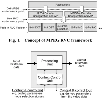
The concept of MPEG RVC framework can be illustrated by Fig. 1. The key difference between RVC and the old MPEG codec standards is that the interface of each coding tools is defined precisely so that they can be used (like LEGO blocks) to build various codecs. The decoder
761
configuration describes how input bitstream can be parsed so that the raw input data to each coding tools can be extracted. A decoder description language is under development so that the configuration of a specific codec (such as H.264) can be described using a (small) configuration bitstream. The decoder configuration bitstream will be processed by an RVC decoder before decoding of a video bitstream conforming to the described standard. Note that after processing a configuration bitstream, the RVC decoder will generate a Global Control Unit (GCU) that governs the operation of the coding tools.
In principle, the configuration description tells the RVC decoder how to wire the coding tools to form a data path. In the RVC framework, each coding tools is called a functional unit (FU) and is specified in Fig. 2 [1]. In Fig. 2, a control signal is a signal embedded in the video bitstream (for example, the width and height of the video frame). A context signal is a signal generated from the processing of bitstream data (for example, the AC prediction direction in the MPEG-4 Part 2 video standard). The context-control unit reads in the context and control signals generated by previous FU’s and generates (or passes on) some context and control signals to the next FU’s based on the result of the processing unit.
A partial example of a configured RVC codec that behaves like an H.264 baseline decoder is shown in Fig. 3. In Fig. 3, the functional blocks encircled in the dashed rectangles will be implemented using the proposed architecture in next two sections.
8×8 IDCT 4×4 GBT prediction4×4 intra- ¼-Pel MC ½-Pel MC H.264 Decoder
Configuration and API Configuration and APIMPEG-4 Decoder
Tools in RVC Toolbox Applications Old MPEG conformance point New RVC conformance point
Fig. 1. Concept of MPEG RVC framework
Processing Unit Input bitstream data Output bitstream data
Context & control [in]
e.g. coding parameters, mode selection signals
Context & control [out]
e.g. derived parameters from the video data
Context-Control Unit
Fig. 2. Definition of a functional unit in RVC
Parser Networks of HW/SW FUs Encoded Bitstream GCU SE1 SE2 SE3 … SEK Data for FU1 Data for FU2 … Data for FUn parsing Decoder Description FU Network Configuration Inloop deblocking filter TQ-1 + Intra/Inter Comp Demux Entropy(coeff)
YCFrameBCR MV/Intra mode decoding Ref 1 Ref 2 Ref 3 Ref 1 Ref 2 Ref 3 mode, model slice info QP Scan-1
Fig. 3. Example of RVC configuration III. PROPOSED SOC ARCHITECTURE FOR RVC
Since the specification of the video decoder configuration language and the actual mechanism of a GCU are still under development at MPEG, this paper proposes a potential VLSI architecture that is suitable for supporting the RVC framework and perform some early analysis on such architecture. The RVC framework actually fits the platform-based design principle of SoC quite well. For maximal flexibility, the GCU will be implemented in software and running on the processor core of an SoC. Each coding tool can be implemented as an IP on the bus with limited configurability via a private register file. The proposed architecture is show in Fig. 4.
It is important to note that in the proposed architecture, hardware FUs and software FUs (stored in SDRAM) can be mixed to compose a network of functional units for a specific codec. It is also important to note that the hardware coding tools are not attached to the main system bus (AMBA AHB) directly. A local bus, Multi-Media Bus (MMB), is used to off-load the bandwidth from the main system bus. In our implementation, MMB is a simplified version of AHB. A two-way DMA is used to transfer data between external SDRAM and internal SRAM banks. The DMA can be invoked from either the ARM core or the coding tool IPs. The reason for multiple SRAM’s on the MMB is to reduce the memory bandwidth requirement for parallel operations of the coding tools.
DMA H.264 ILF ARM SDRAM SRAM 1 AHB MMB H.264 CAVLD DMA Register file DMA Register file H.264 TQ H.264 INTRA H.264 CABAC MPEG-2 IDCT SRAM 2 SRAM 3 MPEG-2 MC H.264 MC DMA H.264 ILF ARM SDRAM SRAM 1 AHB MMB H.264 CAVLD DMA Register file DMA Register file H.264 TQ H.264 INTRA H.264 CABAC MPEG-2 IDCT SRAM 2 SRAM 3 MPEG-2 MC H.264 MC
Fig. 4. SoC architecture for RVC framework
ARM memory AHB Deblocking filter INTRA Decode MC TQ–1 CAVLD
Fig. 5. Hard-wired decoder example
Although local bus and multiple SRAM banks are used to alleviate the bandwidth issue, the performance of this architecture still cannot match that of a hard-wired architecture. For example, a hard-wired H.264 baseline decoder may have a tighter MB decoding pipeline as shown in Fig. 5. There are two main advantages of the architecture in Fig. 5. First of all, the decoding pipeline is controlled by a hard-wired FSM with cycle-based synchronization. On the other hand, for the RVC framework, the GCU controller will be implemented in software, and hence, cannot guarantee cycle-based operation of the pipeline. Another advantage of the hard-wired approach is that it does not require excessive accesses to external memory.
It is important to point out that the purpose of the RVC framework is not to obtain the most efficient design of a single codec, but to allow a flexible and extensible design of codec systems. Multi-standard codec support (or even generating customized codecs on-the-fly) can be achieved by configuring a new GCU via decoder description bitstreams. In the next section, we will study an actual implementation of the proposed architecture in Fig. 4 to get an idea about the cost one has to pay for such flexibility.
IV. IMPLEMENTATION STUDY OF THE PROPOSED SYSTEM
In this section, an implementation of the proposed system architecture (Fig. 4) is investigated. The implementation is based on an SoC emulation platform, the ARM Integrator [6]. The platform is composed of a main board, an ARM 9 processor core module, and a Xilinx VirtexE XCV2000E FPGA logic module. The platform adopts the AMBA bus protocol. The RVC coding toolbox logic of the proposed system is implemented in the FPGA. The local bus protocol, MMB, of the toolbox logic is a reduced version of AHB with much less wires and a minimal implementation of bus arbiter and decoder.
In the proposed system architecture, the controller that drives the operation of the network of FUs is implemented in software. As a result, the codec pipeline is not executed in a lock step fashion but instead driven by the software controller via signals triggered by read/write
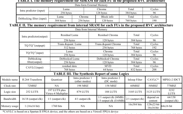
of register files. Each coding tool FU (please refer to Fig. 2) is implemented so that the input bitstream data is coming from a SRAM bank on the MMB and the output bitstream data will be stored in another SRAM bank on the MMB. Block RAMs of the Virtex II FPGA and the ZBT SRAM of the ARM Integrator are used for this purpose. Note that in the proposed architecture, the input/output SRAM banks for a FU (either software or hardware) are dynamically controlled by a memory allocator module (see Fig. 6). Table I and Table II list the required memory for the input data and output data. It is obvious that such implementation is not as efficient as a tightly-coupled pipeline [5] where different pipeline stages are connected via registers or FIFO.
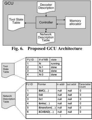
On the other hand, since the system controller is implemented in software, the Global Control Unit of the MPEG RVC framework can be dynamically implemented as in Fig. 6. In Fig. 6, tool state table is a runtime table that record the states of each running FUs. The table is used by the controller to synchronize the operation of the codec pipelines. The network description table is extracted from the decoder description which is attached to the encoded video bitstream. It basically describes the input/output connections (i.e. SRAM banks) of the networks of the functional units. Note that this table can be modified by the memory allocator to allow optimal use of the available SRAM banks. An example of the tool state table and the network description table is shown in Fig.7. GCU Controller Network Description Table Tool State
Table allocatorMemory
Decoder Description GCU Controller Network Description Table Tool State
Table allocatorMemory
Decoder Description
Fig. 6. Proposed GCU Architecture
done N-3 4 … done N-2 3 running N 1 done N-1 2 # of MB state FU ID done N-3 4 … done N-2 3 running N 1 done N-1 2 # of MB state FU ID Tool State Table Network Description Table Parameter Count out addr in addr Pointer FU ID 0 null null &MC(…) 1 0 null null 0x0 2 0 null null 0x1 3 0 null null &intra(…) 4 0 null null &transform(…) 5 0 null null &CABAD(…) 6 … Parameter Count out addr in addr Pointer FU ID 0 null null &MC(…) 1 0 null null 0x0 2 0 null null 0x1 3 0 null null &intra(…) 4 0 null null &transform(…) 5 0 null null &CABAD(…) 6 …
Fig. 7. Tool State and Network Description Tables Also note that in Fig. 7, the “Pointer” field of the network description table stores a pointer to the entry 763
point of software FU and the address of the control register for hardware FU. For hardware FUs, the implementation of the processing unit and context-control unit follows traditional hard-wired IP design methodology where the processing unit is implemented as a data path and the context-control unit is a hard-wired FSM with register files for memory-mapped I/O configuration and signaling. Currently, most of the FUs supported in the proposed platforms are for H.264. The synthesis report of some of the implemented FUs is shown in TABLE III.
V. CONCLUSIONS
This paper introduces the MPEG RVC framework and proposes SoC architecture to support the framework. Since the RVC framework is still under development at MPEG. There is not much research on how the framework can be efficiently supported using an SoC platform design
paradigm. In particular, the reconfigurable video bitstream parser and the decoder configuration language are still yet to be defined by MPEG [7]. However, based on our study, the proposed architecture is very feasible for practical SoC implementation of the RVC framework. Although a reconfigurable video codec cannot compete with a hard-wired codec for performance given current VLSI implementation technology, it is much more scalable in the sense that any new codecs (coding tools) can be added into the platform with minimal effort. The potential of exploring parallelism dynamically at runtime when multiple codecs tasks are issued is also very promising.
V. ACKNOWLEDGEMENT
This research is partly funded by National Science Council, Taiwan, R.O.C., under grant number NSC 95-2219-E-002-012.
TABLE I. The memory requirement for SDRAM for each FU in the proposed RVC architecture
Data form External Memory
Luma Chroma Total Cycles
Intra predictor (input)
256 bytes 128 bytes 384 bytes 96
Luma Chroma Block info Total Cycles
Deblocking filter (input)
384 bytes 256 bytes 120 bytes 760 bytes 190
TABLE II. The memory requirement from internal SRAM for each FUs in the proposed RVC architecture
Data from Internal Memory
Residual Luma Residual Chroma Total Cycles
Intra predictor(output)
256 bytes 128 bytes 384 bytes 96
Trans.&quant. Luma Trans.&quant Chroma Total Cycles
TQ/TQ-1(outpupt)
512 bytes 256 bytes 768 bytes 192
Luma Chroma Total Cycles
TQ/TQ-1(input)
256 bytes 128 bytes 384 bytes 96
Deblocked Luma Deblocked Chroma Total Cycles
Deblocking
filter(output) 256 bytes 128 bytes 384 bytes 96
residual data MVD Total Cycles
CAVLC(input)
768 bytes 64 bytes 832 bytes 208
TABLE III. The Synthesis Report of some Logics
Module name H.264 Transform Quantizer Intra predictor 1 (other modes) Intra predictor 2 (DC mode) Inloop Filter CAVLC* MPEG-2 IDCT
Clock rate 72MHZ NA 198 MHZ 158 MHZ 60MHZ 50MHZ 77MHZ
Logic size 252 LUTS Virtex-4 Multiplier 197 LUTS plus 879 LUTS 188 LUTS 3105 LUTS 3125 LUTS LUTS 3232
Bandwidth 16/18 (output/clk) 1/1 (output/clk) 4/1 output/clk 1/5 output/clk (I16MB)1/1 output/clk (I4MB) 2/1 (output/clk) depend on content (output/clk) 64/158
Memory usage 1 (16x16 bit) 1760 bits NA NA 16x384 bits 128x22-bit 16x16-bit 64x16 bit
*CAVLC is based on a Spartan II FPGA device, and the others are based on a VirtexE FPGA device
REFERENCES
[1] E. S. Jang, K. Asai, and C.-J. Tsai, Study of Video Coding
Tool Repository v5.0, MPEG Meeting Document N7329,
Poznan, July 2005.
[2] C.-J. Tsai, Suggestions on the Direction of VCTR, MPEG
Input Document M12074, Busan, April, 2005.
[3] ISO/IEC MPEG Video Group, Final Call for Proposals on
Reconfigurable Video Coding, MPEG Meeting Document N8070, Montreux, April 2006.
[4] J. Janneck et al., Moses Tool Suite, https://sourceforge.net/projects/mosestoolsuite/.
[5] T.-C Chen, Y.-W. Huang, and L.-G. Chen, “Analysis and
design of macroblock pipelining for H.264/AVC VLSI architecture,” Proc. of IEEE ISCAS 2004, Kobe, 2004. [6] http://www.arm.com/products/DevTools/IntegratorAP.html [7] S. Lee, E. S. Jang, M. Matavelli, C. –J. Tsai, Working
Draft of ISO/IEC 23001-4: Codec Configuration Representation, MPEG Meting Document N8762, Marrakech, Jan. 2007.