Subject terms: grism; dense wavelength division demultiplexer; plunge-cut diamond-turning technology.
Paper 040405R received Jun. 23, 2004; revised manuscript received Aug. 23, 2004; accepted for publication Aug. 23, 2004; published online Feb. 8, 2005.
1 Introduction
In recent years, it has become more and more important to develop a high-capacity and high-speed transmission sys-tem in the rapidly growing information industry. Dense wavelength division demultiplexing 共DWDDM兲 systems provide a new dimension solving capacity and flexibility problems in the optical communication network. The key component in the DWDDM system is a wavelength demul-tiplexer.
To implement DWDDM, several devices and configura-tions have been proposed by many researchers.1–12 Con-ventional filters made of dielectric thin films2 and fiber Bragg gratings3 would not seem suitable to perform as high-channel-count demultiplexers because they filter light in a serial manner and so must be used in combination with other technologies such as interleavers and circulators, which may cause high insertion loss and increase system costs. With advances in waveguide photonic integrated cir-cuits, demultiplexers based on planar arrayed waveguide gratings 共AWGs兲4 have potential use in DWDDM net-works. These devices process optical signals in a parallel manner, which is preferred for high-channel-capacity net-works. Yet their promise of large-volume manufacture abilities is hindered by typically low yields and poor per-formance, including high insertion loss, polarization sensi-tivity, small free-spectral range, and lack of temperature stabilization. They may be used in combination with other technologies such as thermal compensators6 and polariza-tion converters,7 which may cause high insertion loss and system costs. For monodirectional or bidirectional links, optical gratings provide the lowest crosstalk and the largest number of channels. Several papers8 –12 have reported the design and manufacture of demultiplexers by using reflec-tion diffracreflec-tion gratings or concave gratings.
An optical element called a grism, consisting of a trans-mission grating and a prism, is often used in several applications,13–19 i.e., astronomical spectrographs,
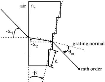
spec-trometers, and so on. In this work, we use the grism instead of reflection gratings in the DWDDM system. The designed DWDDM system is shown in Fig. 1共a兲. The major advan-tages of using transmitting grisms are: 1. a relatively large tolerance for optical alignment, and 2. the ability of reduc-ing the channel spacreduc-ing to 0.4 nm or less by puttreduc-ing the same grisms in a series, as shown in Fig. 1共b兲. When the incident beam passes through two grisms in a series, it makes double diffractions. This configuration would in-crease the resolving power of the DWDDM system by double. The first advantage is usually realized by designing the system as a direct transmitting optics, where one puts a grism in the optical path with its prism vertex angle ad-justed to make the specific order diffraction beam straight along the optical axis at a reference wavelength. If the tilt angle of the grism is ␦␣1, the deviation of the incident
angle for the transmitting grism is ␦␣2
⫽␦␣1cos(␣1)/nscos(␣2), where ns is the refraction index of the grism substrate, as shown in Fig. 2. The angle␦␣2 would be smaller than␦␣1 for the grism. Under the same condition, the deviation angle ␦␣2 equals ␦␣1 for the re-flection grating. The tilt tolerance of the transmitting grism would be larger than the reflection grating.
The grism should be considered to have high optical efficiency, and to be fabricated and replicated easily. There are several methods for fabricating a blazed grism, which has high diffraction efficiency. The most popular method of making a grism is the resin replication of a blazed diffrac-tion grating on a high index prism surface.19 However, most resins have some absorption at infrared wavelengths. Other possible approaches are direct ruling of grooves20or oblique ion-beam etching21on a high refractive index sub-strate. The grism made of high-index material can diffract the beam in the high order with a small vertex angle, which gives a large angular dispersion. However, most optical glasses and crystalline materials are too hard to be pro-cessed by a ruling engine.
KRS-5共ISP Optics Corporation兲 is an infrared material with high refractive index and is transparent in the C band. 0091-3286/2005/$22.00 © 2005 SPIE
025006-1
It has a low melting point of 414.5 °C, low hardness, and could be easily fabricated by using the plunge-cut diamond turning technology and also replicated with conventional embossing techniques. For the prior reasons we chose KRS-5 to make the grism, which could be used for mass production in the future, and make DWDDMs cost less.
In this study, we try to determine whether the grism structure has a desired performance for DWDDM applica-tions.
2 Calculation Method
As shown in Fig. 1共a兲, the DWDDM comprises one colli-mator lens, one grism, and one focal lens. In this work, the 16 channels with a wavelength spacing of 0.8 nm in the C band are designed.
Assuming the surrounding material of this element is air, the angles of light rays given counterclockwise are positive, and those are negative else. The grating equation can be written as
sin共m兲⫺ns共f兲sin共⫺␣2兲⫽m
f
d . 共1兲
Here m is the diffraction order and d is the period of grat-ing. The m is the m’th order diffraction angle measured from the normal to the grating, and the  is the blazed angle of grating, as shown in Fig. 2. ns(f) is the refractive index of KRS-5 material at the reference wavelength f and could be expressed by the following dispersion for-mula,
ns2共兲⫽a0⫹a12⫹a2⫺2⫹a3⫺4⫹a4⫺6⫹a5⫺8, 共2兲 where a0⫽5.66699, a1⫽⫺0.00048, a2⫽⫺0.02409, a3 ⫽2.18849, a4⫽⫺2.44416, and a5⫽0.61575.
Under the on-blaze condition (m⫽⫺␣1), the grating should have maximum efficiency in the m’th order at the wavelengthf. From Eq.共1兲 the blazed angle is given by
sin⫽ mf
关cos␣1⫺ns共f兲cos␣2兴d
, 共3兲
where ␣1 is the input angle of the beam incident on the grism. The blazed grating has a period d⫽12m that is about eight times larger than the reference wavelength f
⫽1550.8 nm. In this case, the grating is polarization inde-pendent and the scalar diffraction theory is available. Within the limitations of the fabrication machine used in this work, the ninth diffraction order and 400 grooves are chosen. If both angles ␣1 and ␣2 equal zero, the blazed angle  is 54.75 deg. A multiple-wavelength Gaussian beam with a divergence angle of 6.13⫻10⫺3deg and Gaussian beam parameter w⫽2.3 mm is normally incident on the input surface of the grism, as shown in Fig. 3. Be-hind the grism, a lens with focal length of 29.47 mm is used.
To verify our design of the grism structure, the field distributions behind the grism are calculated with the Huygens-Fresnel principle22 and given by
Fig. 1 Schematic diagram of a demultiplexer using the grism: (a)
demultiplexing mode and (b) series mode.
Fig. 2 Schematic representation of a grism.
surface of the grism passes through the focal lens, and fo-cuses on the focal plane.
The amplitude distribution of the incident Gaussian beam could be described by
u0共x兲⫽exp
冋
⫺冉
x w冊
2册
⫽冕
⫺⬁ ⬁ 关冑
w exp共⫺2w22兲兴exp共i2x兲d. 共5兲 Neglecting reflection and transmission losses, the trans-mission function of the grism could be written asg共x,兲⫽ 1 N1⌬xp
兺
⫽1N1
exp关⫺i共,p兲兴
⫻rect
冋
x⫺p⌬x⫹N⌬x 1⌬x/2册
, 共6兲 where(,p) is the phase function of the grism, given by 共,p兲⫽2 关 ns共兲⫺1.0兴p⌬z. 共7兲 Under the blazed condition, (,p) equals 2m0p at ⫽f, and Eq.共6兲 could be rewritten as follows,共,p兲⫽2
冋
fnf⫺1
ns共兲⫺1
册
m0p. 共8兲Here m0 is the designed diffraction order of the grism. A Gaussian beam normally illuminates the grism, and the field distribution behind the grism equals u(x,) ⫽u0(x)g(x,). In the Kirchholff approximation, the Fou-rier transform of u(x,) is
U共,兲⫽
冕
⫺⬁ ⬁ u共x,兲exp共⫺i2x兲dx ⫽冕
⫺⬁ ⬁exp关iN1共⫺兲⌬x兴sinc关共⫺兲⌬x兴
⫻关
冑
w exp共⫺2w22兲兴 1 N1 where m⫽冋
f nf⫺1 ns共兲⫺1 册
m0⫹共⫺兲⌬x. 共10兲In Eq.共9兲, the summation vanishes, except that the follow-ing condition is satisfied:
兺
p⫽1 N1 exp共⫺i2m p兲⫽再
N1, m⫽integer 0, otherwise . 共11兲If m equals an integer, the intensity of the m’th order dif-fraction light at wavelength could be given by
兩U共m,兲兩2 ⫽
冏
冕
⫺⬁ ⬁ exp冉
iN1再
m⫺冋
f nf⫺1 ns共兲⫺1 册
m0冎冊
⫻sinc再
m⫺冋
f nf⫺1 ns共兲⫺1 册
m0冎
⫻冑
w exp关⫺2w22兴d冏
2 , 共12兲where the factor
冑
w exp关⫺2w22兴 represents the spatial divergence of diffraction beams. In this work, since the incident Gaussian beam has a large beam waist w ⫽2.3 mm, the contribution of the factor is only from a very small value, which has a negligible influence on the other functions in the integral of Eq.共12兲. The other functions in the integral can be considered to be independent of, and we have 兩U共m,兲兩2⫽冉
sinc再
m⫺冋
f nf⫺1 ns共兲⫺1 册
m0冎冊
2 . 共13兲The m’th order diffraction efficiency of the grism is de-fined as
共m,兲⫽ 兩U共m,兲兩 2 兺m⬘兩U共m
⬘
,兲兩2The total optical crosstalk in channel j is defined by the signal-to-noise ratio共SNR兲,
SNRj⫽ ⌽j j 兺i⫽ j⌽i j
, 共15兲
where ⌽i j indicates the crosstalk power in channel j of wavelengthj from other channels, and ⌽j j is the output power of wavelengthj in channel j.
The influences of fabrication errors on the optical per-formance are evaluated by using the deviation probability function. We assume that the deviation of grating width⌬x and depth ⌬z is independent, and the deviation values could be described by the Gaussian random probability distributions,23 fG共␦x, j兲⫽ 1 共2x 2兲1/2exp关⫺共␦x, j⫺ax兲 2/2 x 2兴, 共16兲 fG共␦z, j兲⫽ 1 共2z 2兲1/2exp关⫺共␦z, j⫺az兲 2/2 z 2兴, j⫽1,2,...,N2, 共17兲
where␦x, j(␦z, j), ax(az), andx(z) represent the devia-tion value, mean value, and variance value of the grating width 共depth兲, respectively. The suffix j denotes the j’th grating groove. The new width ⌬x⫹␦x, j and depth ⌬z
⫹␦z, j for each groove are given by Eqs. 共16兲 and 共17兲, respectively. The field distributions with fabrication errors are obtained by substituting them into Eq.共4兲.
3 Calculation Results
The intensity distributions as a function of position on the focal plane are shown in Fig. 4, where the spatial separation between two adjacent channels, corresponding to the wave-length spacing of 0.8 nm, is 32.57m and the waist spot size of the focal Gaussian beam at the reference wavelength is about 20.9m. The transmission spectra of the designed DWDDM as a function of wavelength for 16 channels are Fig. 4 A part of the calculated transverse intensity distributions on
the focal plane.
Fig. 5 Calculated transmission spectra of the designed DWDDM.
Fig. 6 A part of the calculated transverse intensity distributions with
variance values␦x⫽␦z⫽0.05m.
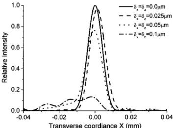
Fig. 7 Calculated transverse intensity distributions at reference
shown in Fig. 5, where we can see that the designed de-multiplexer has high optical efficiency and signal-to-noise ratio, and the full width at half maximum共FWHM兲 of each channel spectrum is 0.678 nm, which is smaller than the requirement 0.8 nm. We calculated and analyzed the influ-ences of fabrication errors on the optical performance. In this calculation, we assume that both mean values axand az are zero, and both variance values␦xand␦z are 0.05 m. With the deviation values given by Eqs.共16兲 and 共17兲, the intensity distributions at the central wavelength of each channel were calculated, and a part of the results are shown in Fig. 6. The intensity distributions at reference wave-lengths with different variance values are shown in Fig. 7 for comparison.
4 Experimental Results
The blazed grating was fabricated directly on the hypot-enuse of a KRS-5 prism by using plunge-cut diamond turn-ing technology24 共Machi NCAU-300E兲. This technology overcomes much of the turning mark problem24 by cutting with the edge of the diamond tool, as shown in Fig. 8. A photograph of the fabricated grism is shown in Fig. 9. Fig-ure 10 exhibits a part of the profile of the surface relief profile for the fabricated grating, measured with an optical profilemeter共Zygo New View 5000兲. Table 1 lists the pro-file errors of gratings produced in the making process. To check the performance of the fabricated grism, we mea-sured the intensity distributions on the focal plane. Table 2
lists the calculated and measured optical loss for each com-ponent. Those losses are caused by reflection that can be reduced by the antireflection coating on the input and out-put surfaces.
The experimental setup for measuring the spot size and relative position of each channel wavelength is shown in Fig. 11. The incident beam with a bandwidth of 0.2 nm was provided by a tunable laser source共Anritsu MG9541A兲. An infrared charge-coupled device 共CCD兲 camera 共Electro-physic 7290A兲 with 20⫻ objective was placed on the focal plane to record the output image for discrete wavelengths with wavelength separation of 0.8 nm. The intensity distri-bution at the reference wavelength is shown in Fig. 12. In this case, the light at the reference wavelength propagates along the optical axis and does not deflect by the grism. Its tion.
Fig. 9 Photographs of fabricated grating: (a) real sample and (b) a
part of the enlarged grating.
Fig. 11 Experimental setup for measuring the spot size and relative
position of each wavelength on the focal plane.
Fig. 12 Measured intensity distribution at reference wavelengthf
⫽1550.8 nm on the focal plane.
Fig. 13 Comparison between the calculated and measured
trans-verse intensity distributions on the focal plane at the reference wavelengthf⫽1550.8 nm.
Fig. 14 A part of the measured transverse intensity distributions on
the focal plane.
Fig. 15 Comparison between the calculated and measured
diffrac-tion efficiency of the grism for each channel wavelength.
Table 1 Comparisons between designed and measured depth and
width of grating.
Designed Measured Error
Depth of grating⌬z 9.8 9.7 ⫾0.4 1.02%
Width of grating⌬x 6.93 6.78⫾0.3 2.26%
Table 2 Comparisons between calculated and measured optical
transmittance of each component.
Calculated Measured
Collimator lens 0.99 0.96
Grism 0.684 0.672
spot is about circular symmetry, but there are a few stray spots in the transverse direction. This could be due to the turning errors of the grating and the residues in the ravine of the grating groove. To verify this point, we compare this result to that calculated with grating groove errors corre-sponding to the variance value␦x⫽␦z⫽0.05m, as shown in Fig. 13, where some small side peaks can be found. A part of the measured transverse intensity distributions are drawn in Fig. 14. The spot size and the spot separation between two adjacent channels are about 21.3 and 36.27 m, respectively. The optical diffraction efficiency of the grism for each wavelength channel corresponding to an in-ner area of 24 m diam was measured. The results are compared with the calculated, as shown in Fig. 15. The setup for measuring the transmission spectra of each chan-nel is shown in Fig. 16. The incident beam with broad spectral band共1520 to 1570 nm兲 was provided by the am-plified spontaneous emission 共ASE兲 light source 共Unice NA0101兲, and the transmission spectra for each channel were recorded by a spectrometer 共Jobin Yvon Triax 550兲. The measured transmission spectra of 16 channels are dem-onstrated in Fig. 17, where the spectral passband of each channel at the FWHM is about 0.7 nm. The comparison
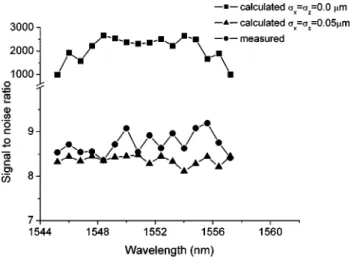
between the calculated and measured signal-to-noise ratio is shown in Fig. 18. The difference between the calculated and the measured should be mainly caused by the imper-fections of the grating, such as deviation of the groove profile, pitch irregularity, etc. The calculation with variance value (␦x⫽␦z⫽0.05m) verifies this point, as shown in Fig. 18.
5 Conclusion
A KRS-5 grism is used to design and fabricate a low-loss demultiplexer for a DWDDM system. The performance of this demultiplexer is also calculated with the Huygens-Fresnel principle. The influences of fabrication errors on the optical performance are analyzed. The KRS-5 grism is successfully fabricated by precise plunge-cut diamond-turning technology. Numerical calculations and experimen-tal measurements demonstrate that both agree very well. The demultiplexer has 16 channels with a wavelength spac-ing of 0.8 nm in the C band. Furthermore, narrower wave-length spacing could be obtained by using the same grisms in a series without redesigning the system.
Acknowledgments
The authors gratefully acknowledge the National Science Council of the Republic of China for financial support of this research under project number NSC 92-2215-E-009-051, and the Precision Instrument Development Center for providing the measurement equipment. The grism was fab-ricated by the Mechanical Industry Research Laboratories of the Industrial Technology Research Institute.
References
1. A. Othonos, J. Bismuth, M. Sweeny, A. P. Kevorkian, and J. M. Xu, ‘‘Superimposed grating wavelength division multiplexing in Ge-doped SiO2 Si planar waveguides,’’ Opt. Eng. 37共2兲, 717–720 共1998兲. 2. A. Michael and S. Cobey, ‘‘Optical multiplexing device,’’ U.S. Patent
No. 5,583,683共1996兲.
3. F. Bilodeau, D. C. Johnson, S. Theriault, B. Malo, J. Albert, and K. O. Hill, ‘‘An all fiber dense wavelength division multiplexer/ demultiplexer using photoimprinted Bragg gratings,’’ IEEE Photonics
Technol. Lett. 7共4兲, 388 共1995兲.
4. J. F. Viens, C. L. Callender, J. P. Noad, L. A. Eldada, and R. A. Norwood, ‘‘Polymer-based waveguide devices for WDM applica-tions,’’ Proc. SPIE 3799, 202–213共1999兲.
Fig. 16 Experimental setup for measuring the transmission spectra
of each channel.
Fig. 17 Measured transmission spectra of the fabricated DWDDM.
Fig. 18 Comparison of the measured SNR with the calculated
SNRs that correspond to a perfect grating (␦x⫽␦z⫽0.0m) and an
5. V. Minier, A. Kevorkian, and J. M. Xu, ‘‘Superimposed phase gratings in planar optical waveguides for wavelength demultiplexing applica-tions,’’ IEEE Photonics Technol. Lett. 5, 330–333共1993兲.
6. N. Ooba, Y. Hibino, Y. Inoue, and A. Sugita, ‘‘Althermal silica-based arrayed-waveguide grating multiplexer using bimetal plate tempera-ture compensator,’’ Electron. Lett. 36共21兲, 1800–1801 共2000兲. 7. Y. Inoue, Y. Ohmori, M. Kawachi, S. Ando, T. Sawada, and H.
Taka-hashi, ‘‘Polarization mode converter with polyimide half waveplate in silica-base planar lightwave circuits,’’ IEEE Photonics Technol. Lett. 6共5兲, 626–628 共1994兲.
8. M. Kajita, K. Kasahara, T. J. Kim, D. T. Neilson, I. Ogura, I. Red-mond, and E. Schenfeld, ‘‘Wavelength-division multiplexing free-space optical interconnect networks for massively parallel processing systems,’’ Appl. Opt. 37共18兲, 3746–3755 共1998兲.
9. K. I. Aoyama and J. I. Minowa, ‘‘Low-loss optical demultiplexer for WDM systems in the 0.8 micrometer wavelength region,’’ Appl. Opt. 18共16兲, 2834–2836 共1979兲.
10. W. J. Tomlinson, ‘‘Wavelength multiplexing in multimode optical fi-bers,’’ Electron. Lett. 16共8兲, 2180–2194 共1977兲.
11. B. D. Metcalf and J. F. Providakes, ‘‘High-capacity wavelength de-multiplexer with a large-diameter grin rod lens,’’ Appl. Opt. 21共5兲, 794 –796共1982兲.
12. M. Seki et al., ‘‘20-channel micro-optic grating demultiplexer for 1.1–1.6 micrometer band using a small focusing parameter graded-index rod lens,’’ Electron. Lett. 18共6兲, 257–258 共1982兲.
13. N. Ebizuka, M. Lye, and T. Sasaki, ‘‘Optically anisotropic crystalline grisms for astronomical spectrographs,’’ Appl. Opt. 37共7兲, 1236–1242
共1998兲.
14. W. A. Traub, ‘‘Constant-dispersion grism spectrometer for channeled spectra,’’ J. Opt. Soc. Am. A 7共9兲, 1779 共1990兲.
15. S. Kane and J. Squier, ‘‘Grism-pair stretcher compressor system for simultaneous second- and third-order dispersion compensation in chirped-pulse amplification,’’ J. Opt. Soc. Am. B 14共3兲, 661 共1997兲. 16. B. A. Richman, S. E. Bisson, R. Trebino, M. G. Mitchell, E. Sidick,
and A. Jacobson, ‘‘Achromatic phase matching for tunable second-harmonic generation by use of a grism,’’ Opt. Lett. 22共16兲, 1223–1225
共1997兲.
17. C. Pitris, B. E. Bouma, M. Shiskov, and G. J. Tearney, ‘‘A grism-based probe for spectrally encoded confocal microscopy,’’ Opt. Exp. 11共2兲, 120–124 共2003兲.
18. N. Ebizuka, K. Oka, A. Yamada, M. Watanabe, K. Shimizu, K. Ko-date, M. Kawabata, T. Teranishi, K. S. Kawabata, and M. Iye,
‘‘De-velopment of volume phase holographic共VPH兲 grism for visible to near infrared instruments of the 8.2 m Subaru telescope,’’ Proc. SPIE
4842, 319–328共2003兲.
19. W. A. Rense, ‘‘Techniques for rocket socket solar UV and for UV spectroscopy,’’ Space Sci. Rev. 9, 234 –264共1966兲.
20. L. Weitzel, A. Krabbe, H. Kroker, N. Thatte, L. E. Tacconi-Garman, M. Cameron, and R. Genzel, ‘‘3D: The next generation near-infrared imaging spectrometer,’’ Astron. Astrophys., Suppl. Ser. 119, 531–546
共1996兲.
21. Y. Aoyagi and S. Namba, ‘‘Blazed ion-etched holographic gratings,’’
Opt. Acta 23, 701–707共1976兲.
22. S. Nonogaki, ‘‘A rigorous solution of two-dimensional diffraction based on the Huygens-Fresnel principle,’’ Jpn. J. Appl. Phys., Part 1 28共5兲, 786–790 共1989兲.
23. W. H. Press, S. A. Teukolsky, W. T. Vetterling, and B. P. Flannery,
Numerical Recipes in Fortran, 2nd ed., pp. 279–280, Cambridge,
Univ. Press, Boston, MA共1992兲.
24. M. B. Fleming and M. C. Hutley, ‘‘Blazed diffractive optics,’’ Appl.
Opt. 36共20兲, 4635–4643 共1997兲.
Jyh-Rou Sze received his BS degree from the Department of
Elec-trical Engineering at Private Chinese-Culture University in 1997 and MS degree from the Department of Electro-Optical Engineering at National Chiao-Tung University in 1999, where he is currently work-ing toward his PhD. His current interests include the numerical methods applied to designing diffractive optical elements that have particular functions and fabricating the designed elements.
Mao-Hong Lu graduated from the Department of Physics at Fudan
University in 1962. He then worked as a research staff member at the Shanghai Institute of Physics and Technology, Chinese Acad-emy of Sciences, from 1962 to 1970, and the Shanghai Institute of Laser Technology from 1970 to 1980. He studied at the University of Arizona as a visiting scholar from 1980 to 1982. He is currently a professor at the Institute of Electro-Optical Engineering, National Chiao-Tung University.