©2007 National Kaohsiung University of Applied Sciences, ISSN 1813-3851
Investigation of Fomulation of the Energy Release Rate in the Fracture
Mechanics of Short Fiber Composite
Thanh-Phong Dao1, Hieu Giang Le2, Shyh-Chour Huang1,*
1Department of Mechanical Engineering,
National Kaohsiung University of Applied Sciences Kaohsiung, Taiwan, R.O.C.
2Department of Mechanical Engineering,
University of Technical Education Ho Chi Minh City, Vietnam *E-mail: shuang@cc.kuas.edu.tw
Abstract
The aim of the paper is to investigate the fracture of short carbon fiber reinforced PA66 (20wt% fibers) and formulate the formula of the energy release rate GIC. Experimental specimens were injection-molded in end-gated
molds with dimension 4×10×80 mm. Most of short fibers are oriented in the same direction of the plastic flow during injection process. The volume fraction of short fibers is about 13%. Very sharp notches (angle 25°, tip radius R=0.015mm) of different depths were created to the edge-sides (narrow sides of the specimens). The experiments have been carried out at the ambient temperature. Charpy impact test was used to examine the impact on specimens. Fracture tests were performed with the machine in the position of edgewise impact according to the standard ISO 179. By observing and analyzing the fracture surfaces of specimens, a fracture mechanism of the short fiber composite has been developed and modeled. Based on the model and the experimental results, the energy release rate GIC can be calculated. As a result, the formula for calculating GIC has been established in order
to estimate and predict fracture properties of the material for the unidirectional short fiber composite.
Keywords: Short Carbon Fiber Reinforced Polyamide 66, Composite Materials, Fracture Mechanics, Energy Release Rate.
1. Introduction
During the past several years, an increasing amount of attention has been given to mechanical properties of fiber-reinforced polymers. Recently, researchers have shown an increased interest in determining the parameters influent on dynamic fracture behavior and estimating ways to compute the energy release rate for these materials. One of the reasons for this interest is that fiber-reinforced polymer are finding an increasing number of applications in many structural automotive components.
In 1999, Kukureka et al. [1] studied and examined the friction and wear of of short fibre-aramid, carbon, and glass fiber-reinforced PA66 in rolling-sliding contact. The results of the article found that the friction of the matrix material is similar when using aramid-fibre PA66. Also, in 1999, Varelidis et al. [2] conducted an experiment on coating polyamide on carbon fibers to examine the influents of coating polyamide on mechanical behaviors of unidirectional carbon composites. Their results identified that initiation fracture toughness increases for both polyamide coatings. Beckert et al. [3] investigated on utilizing finite element model for calculating of energy release rate for single. The results showed that the dominant instable interface crack extension to begin in a
stable way due to a minimum in energy release rate for a very short crack length. Another study by Botelho et al. [4] investigated and compared tensile and compressive strength, shear stress of fabric and unidirectional carbon fibers-reinforced polyamide 6 and polyamide 6/6. The results of the paper revealed that an increase of carbon fiber content increases slightly the composite elastic modulus, tensile and compressive strength. Jacobson et al. [5] investigated oxidative degradation of polyamide 66 and polypropylene specimens undergone to tensile testing. Their experimental results found that the stress-induced adiabatic heating causes thermally unstable hydroperoxides decomposing. In 2003, according to Wang et al. [6] computed for energy release rate stress and intensity factor of a non-homogeneous delaminated composite plate . The results of the study found that the relationship between the global and local mode mix decompositions is established. According to Cosme et al. [7] by using phase contrast imaging technique, a high resolution reconstructions of carbon fiber-reinforced polyamide is achieved.
More recent study in 2011, Tian et al. [8] studied static and dynamic mechanical behaviors of composites which were reinforced by micro- and nano-sized short fibers were made by mechanically blending of silanized fibrillar silicate (FS) nanofibers and polyamide66 (PA-66) microfibers. The experimental results revealed that incorporation of silanized fibrillar silicate nanofibers with polyamide 66 (PA-66) microfibers in an appropriate volume ratio.
Almost above studies have already investigated mechanical properties of short carbon fiber-reinforce PA66 and other fibers-reinforced PA66. However, ways formulate a formula of the energy release rate for short carbon fiber-reinforce PA66 has not yet been studied deeply.
The objective of the paper is to research the fracture mechanism of short fiber composite with polymer matrix. The fracture mechanism of short fiber composite will be discussed in the scope of mode I of loading and physical interaction. The model has been calculated on the hypothesis that lengths fibers of the composite are equal and the fibers have the same direction as that of plastic flow during the injection process.
2. Experimental Analysis of the Energy Release Rate
2.1. Materials and Specimens
Short carbon fiber reinforced PA 66 (Ultramid A3WC4 with 20wt% fibers) was used in the experiment. Specimens of the composite for Charpy impact tests were injection-molded in end-gated molds with dimension 4× 10×80 mm. Most of short fibers are oriented in the same direction of the plastic flow during injection process. The volume fraction of short fibers is about 13%. Very sharp notches (angle 25°, tip radius R=0.015mm) of different depths were created to the edge-sides (narrow sides of the specimens). The experiments have been carried out at the ambient temperature. Figure 1 shows the notched specimens and direction of blow.
Fig.1 Notched specimens and direction of blow B = 4mm, D = 10mm, L = 80mm
L B D R=0.015 250 Direction of blow
2.2. Testing Equipment
A Charpy instrumented impact pendulum machine made by CEAST. Fracture tests were performed with the machine in the position of edgewise impact according to the standard ISO 179. The experimental parameters were set as the following:
- Support span: S = 60mm, i.e., S/D = 0.6 - Mass of pendulum hammer: 1.09625kg - Impact speed: V=2.9 m/s
- Impact energy of pendulum: 4.6 J. Sample time 5s.
2.3. Experiment Results
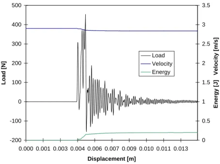
During the experiments, characteristic load-displacement, velocity-displacement and energy-displacement traces of tested specimens of short carbon fiber reinforced PA66 at the room temperature can be displayed on the software window (Fig. 2). The total fracture energy Ea can be determined through the experiment.
-200 -100 0 100 200 300 400 500 0.000 0.001 0.003 0.004 0.006 0.007 0.009 0.010 0.011 0.013 Displacement [m] Load [N] 0 0.5 1 1.5 2 2.5 3 3.5 Energy [J] Velocity [m/s] Load Velocity Energy
Fig. 2 Characteristic load-displacement, velocity-displacement and energy-displacement traces of tested specimens of short carbon fiber reinforced PA66 at room temperatures
Then, the energy release rate GIC can be determined through the experiments by the below formula [9, 10]:
BD
E
G
aIC
(1)Then, the stress intensity factor KIC can be determined by the following relationship [9]:
E
K
G
IC IC 2
(2) where:B is the thickness of a specimen, D is the width of the specimen, Ea is the total fraction energy,
is the energy calibration factor and dependent on the crack dimension of a specimen.
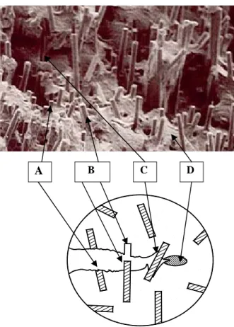
The fracture surface of a specimen and the fracture mechanisms of the material are shown in the Figure 3. By observing the fracture surfaces of specimens, we see that the total fracture energy consists of fiber breakage energy, fiber pull out energy, fiber matrix debonding energy, and fracture energy of matrix.
3. Analysis of the Energy Release Rate Using Modelling
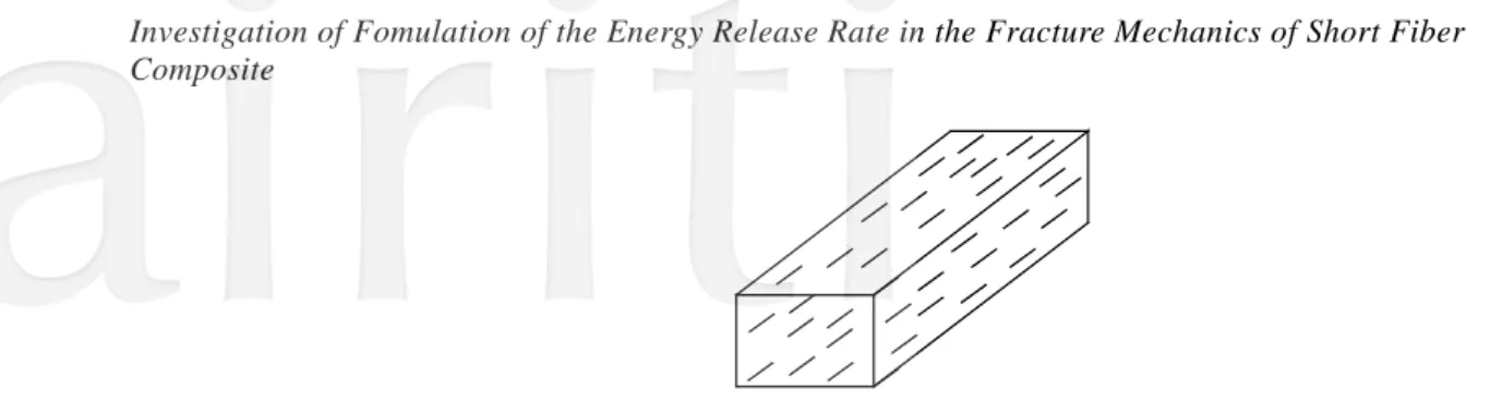
Assume that lengths of all short fibers are the same and equal to L (L > Lc), where Lc is the critical length of fiber breakage [11] and that short fibers are oriented in the same direction as that of plastic flow during the injection process and distributed uniformly (Fig. 4). The material becomes unidirectional short fiber composite. Volume fractions of fiber and matrix are denoted by Vf and Vm respectively (Vf + Vm = 1). Thus, to determine the
total fracture energy Ea or the fracture energy per area unit Ua for using the modelling, then determine the energy
release rate and stress intensity factor
Fig. 3 Fracture mechanisms on a microphotograph of a fracture surface of a specimen at 200C
A.ber fracture. B.ber pull-out. C.ber – matrix debonding.
D.acture of matrix
Fig. 4 hort fibers are oriented in the same direction and distributed uniformly
Due to the above hypothesis of uniform distribution of fibers in the same direction, the area fractions of fiber and matrix in all intersection surfaces normal to fiber direction are the same, denoted by Sf and Sm respectively (Sf
+ Sm =1). Consider a model with the length of 2L and intersection surface (Fig.5).
Fig.5 A model with length of 2L and intersection surface in the middle
The volume of fibers (
v
f ) and that of matrix (v
m) in the model can be calculated as follows:L
S
dL
S
v
f2
L f2
f 0
(3)L
S
dL
S
v
m L m m
2
0
2
(4)On the other hand, the volume of fibers and matrix in the model can be calculated in other way:
c f f
V
v
v
.
(5) c m mV
v
v
.
(6) where: m f cv
v
v
, cv
is the total volume of composite,v
f andv
m are the volume fraction of fiber and matrix respectively.From Eqs. (3), (5), (4) and (6), we have:
c f f
L
V
v
S
2
(7) c m mL
V
v
S
2
(8)From (7) and (8), we have:
m f m f
S
S
V
V
or1
1
1
m f m f m m f fV
V
S
S
V
S
V
S
(9) and we deduce: f fV
S
(10) m mV
S
(11)Because of uniform distribution of fibers around a cross-section, the probability of fibers pulled out (Pfp) with
lengths in a range of 0 and Lc can be calculated as follows:
L
L
P
cfp
(12)On the other hand, probability of fibers fractured or broken (Pfb) is:
fp fp
P
P
1
(13) where [11]: 02
fu cd
L
(14)d is the diameter of fiber.
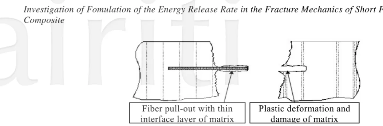
Fig. 6 illustrates the case of shear strength of the interface bond, b, is higher than shear strength of the matrix m
Fig. 6 the interface bond b is higher than shear strength of the matrix m
Fig. 7 shows the case of shear strength of the interface bond b is lower than shear strength of the matrix
m: b
0
.Fig. 7 the interface bond b is lower than shear strength of the matrix m
According to the above hypothesis, probability of the fibers debonded from matrix is zero. From Eqs. (10) and
(12), the area fractions of broken fibers and pulled-out fibers are respectively:
L
L
V
P
V
P
S
S
c f fp f fp f fp1
(15)L
L
V
P
V
P
S
S
c f fp f fp f fp
(16)Thus, the number of pulled-out fibers per area unit is:
2 2
4
4
d
L
L
V
d
S
N
fp fp f c
(17)Fracture energy of pulled-out fibers per unit area:
fp fp
fp
N
E
U
(18)Fiber pull-out with thin
interface layer of matrix Plastic deformation and damage of matrix
Fiber pull-out without plastic deformation of matrix:
τ
0
τ
bwhere:
E
fpis the average energy for pulling out a fiber and can be calculated as the following:2
0 0 0d
L
ddL
E
L c fp tb
(19) where:2
c tbL
L
thus,U
fp
N
fpE
fp2
4
0 2d
L
d
L
V
U
fL c fp c
(20) fu c f fpdL
L
V
U
(21)Fracture energy of broken fibers per unit area:
fu fu c f fu fu fb fb
L
L
V
S
U
1
(22) Or f fu c f fbE
L
L
V
U
21
(23)Fracture energy of matrix per unit area:
mu mu f mu mu m mb
V
V
U
(
1
)
(24) where: mu
is the tensile strength of the matrix mu
is the breaking strain of the matrixFracture energy per area unit Ua includes fracture energy of broken fibers (Ufb), fracture energy of pulled-out
m fp fp a
U
U
U
U
(25) mu mu m fu c f f fu c f aV
dL
L
V
E
L
L
V
U
21
(26)According to (18), GIC can be determined by the following formula:
1
1
2
c fu m mu mu f f fu c f ICV
dL
L
V
E
L
L
V
G
(27)The results of analyzing shows that the energy release rate GIC can be determined by experiment (Eq. 1) and
modeling (Eq. 27).
4. Conclusion
The article focuses on the fracture of short carbon fiber reinforced PA66 (20wt% fibers) and formulate the formula of the energy release rate GIC. The critical energy release rate GIC and stress intensity factor KIC, can be
determined from experiment data. By observing the fractured cross-sections of the specimens and analyzing the fracture processes, fracture mechanism of short carbon fiber reinforced PA66 has been mentioned. Through the hypothesis and the model of the problem, the formula (27) for calculating GIC has been established and thanks to
this, fracture properties of the material can be estimated and predicted for the unidirectional short fiber composite.
References
[1] Kukureka, S.N., Hook, C.J. e, Rao, M., Liao, P., and Chen, Y.K., “The effect of fibre reinforcement on the friction and wear of polyamide 66 under dry rolling–sliding contact”, Tribology International, Vol. 32, pp. 107–116, 1999.
[2] Varelidis, P.C., McCullough, R.L. and Papaspyrides, C.D., “The effect on the mechanical properties of carbon/epoxy composites of polyamide coatings on the fibers”, Composites Science and Technology, Vol. 59, pp. 1813-1823, 1999. [3] Beckert, W. and Lauke, B., “Finite element calculation of energy release rate for single-fibre pull-out
test”, Computational Materials Science, Vol. 5, pp. 1-11, 1996.
[4] Botelhoa, E.C., Figiel, Rezendeb, M.C., and Lauke, B., “Mechanical behavior of carbon fiber reinforced polyamide composites”, Composites Science and Technology, Vol. 63, pp. 1843–1855, 2003.
[5] Jacobson, K., Stenberg, B., Terseliusb, B., and Reitberger, T., “Stress-induced chemiluminescence from injection moulded polyamide 66 and polypropylene”, Polymer Degradation and Stability, Vol. 64, pp. 17-20, 1999.
[6] Wang, J. L. and Qiao, P. Zh., “On the energy release rate and mode mix of delaminated shear deformable composite plates”, International Journal of Solids and Structures, Vol. 41, pp. 2757–2779, 2004.
[7] Cosme, F., Bernasconi, A., and Sodini, N., “Phase contrast micro-tomography and morphological analysis of a short carbon fibre reinforced polyamide”, Composites Science and Technology, Vol. 71, pp. 23–30, 2011.
[8] Tian, M., Yin, S., Zou, H., Su, L., and Zhang, L., “Static and dynamic mechanical properties and fracture morphology of EPDM composites containing silicate nanofibers and short PA-66 microfibers”, Composites: Part B, Vol. 42, pp. 1937–1944, 2011.
[9] Reid, S.R., Zhou, G., “Impact Behaviour of Fibre-Reinforced Composite Materials and structures”, ISBN 1 85573 423 0, October 2000.
[10] Moore, D.R., Pavan, A. and Williams, J.G., “Fracture mechanical testing methods for polymers, adhesives and composites”, publication of European Structural Integrity Society No. 28, Elsevier 2001.