High Speed Pilot-less Sampling Frequency Acquisition
for DMT Systems
Ching-Chi Chang and Chorng-Kuang Wang
Graduate Institute of Electronics Engineering and Department of Electrical Engineering National Taiwan University
Taipei 106, Taiwan R.O.C. [email protected]
Abstract—This paper presents a sampling frequency offset
estimation in time domain for discrete multitone (DMT) systems. Cyclic prefix (CP) enables this estimation without pilots. The proposed algorithm realizes sampling frequency estimation on each sample within the last period where the CP copied from. The sampling-rate iteration method markedly improves acquisition speed and jitter performances. Simulations show that this method can synchronize DMT systems in both AWGN channels and twisted pair copper wires along with non-ideal factors. Practical examples of the very-high bit-rate digital subscriber lines (VDSL) are used to illustrate results.
I. INTRODUCTION
Discrete multitone (DMT) modulation is recognized to efficiently transmit data over spectrally shaped noisy channels [1], and has been standardized for broadband communications over existing copper networks [2, 3]. The significant drawback of DMT systems is the sensitivity to synchronization errors, including DMT symbol offset and mismatched sampling clocks. The receiver has to employ a timing recovery to correct the sampling clock since inter-carrier-interference (ICI) power is proportional to the square of the sub-carrier index and the sampling clock offset [4].
Practically, an adaptive receiver is preferable to combat varying transmission environments. The timing recovery can utilize a digital phase-locked loop (PLL) to acquire and maintain the sampling clock, thus, the bandwidth and the sampling rate of the PLL dominate the acquisition speed [5]. The state-of-the-art timing estimations depend on observing rotational pilots in the frequency domain [4, 8]. Since pilots arrive at the symbol rate, e.g. about 4kHz in VDSL systems, the PLL must be narrow bandwidth and take a long time to compensate the sampling clock, e.g. 200-symbol time in VDSL systems [6, 7]. As the sub-carrier number grows, the propagation error of the sampling phase degrades the jitter performance of the timing recovery. Besides, if the occasional radio frequency interference (RFi) exists in the
corresponding frequency of the pilot, the synchronization mechanism collapses.
In this paper, we present a time domain estimation method which can directly calculate each phase error between the samples in the cyclic prefix (CP) and its repeat within a DMT symbol. By applying a proportional-and-integral (PI) filter in the PLL, the receiver can estimate and compensate the sampling clock at the analog-to-digital (A/D) sampling rate, e.g. 35MHz in VDSL systems.
This paper organizes as follows. Section II introduces the DMT system model. Section III presents the synchronization in DMT systems. Section IV derives the proposed time domain timing estimation method for DMT systems. Simulations and practical considerations are shown in Section V. And the conclusions are drawn in Section VI.
II. DMTSYSTEM MODEL
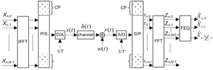
The DMT transceiver, shown in Fig. 1, splits the available bandwidth into a number of sub-bands. In each sub-band a QAM-modulated sub-carrier is transmitted. Denote Xn,k the constellation point which modulates the kth sub-carrier during the nth DMT symbol. An N-point Inverse Fast Fourier Transform (IFFT) digitally performs modulations. In order to generate real signals, Xn,k must satisfy Xn,0=0 and (Xn,k)*=Xn,N-k, k∈[0, N-1]. An appended L-sample CP guarantees orthogonal signals at the receiver. The digital-to-analog (D/A) converter which runs at the rate 1/T transmits the continuous signal s(t),
Fig. 1. The DMT transceiver system.
This program is supported by the National Science Council (NSC), Taiwan R.O.C. P/S IFFT P/S channel FFT Zn,0 Zn,1 D/A A/D ) (t w ) (t h ) (t s r(t) FEQ Zn,N/2-1 0 , ˆ n X 1 , ˆ n X 1 2 , ˆ − N n X rn,0 rn,1 rn,N-1 CP S/P S/P Zn,N-1 CP 1/T’ 1/T Xn,0 Xn,1 Xn,N-1
4895
0-7803-8834-8/05/$20.00 ©2005 IEEE.
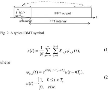
Fig. 2. A typical DMT symbol. , ) ( 1 ) ( 1 0 , ,
∑
∑
− = ∞ −∞ = = N k k n k n n t ψ X N t s (1) where ≤ < = − = − − . , 0 0 , 1 ) ( ), ( ) ( 2 ( ) , else T t t u nT t u e t ψ s s nT T t f π j k n s g k (2)Tu and Tg are IFFT and CP intervals respectively, and Ts=Tu+Tg. The sampling period T=Tu/N, and the sub-carrier frequency fk=k/Tu, k∈[0, N-1].
In the receiver, the A/D converter digitizes the received signal r(t) at the rate 1/T’, where
r(t)=s(t)⊗h(t)+w(t), (3) h(t) is the impulse response of the channel, and w(t) is the AWGN. In order to detect the transmitted symbols, the receiver processes blocks of N+L consecutive samples and removes the first L samples of each block. The FFT demodulates the remaining samples and outputs
Zn,m=Xn,mHn,m+Wn,m, m=0, 1, …, N-1, (4) where Hn,m and Wn,m are channel and AWGN frequency responses at the mth sub-carrier during the nth DMT symbol. A frequency domain equalizer (FEQ) multiplies each indexed FFT output a complex tap to perform channel equalization.
III. SYNCHRONIZATION IN DMTSYSTEMS
In order to find the start point of the FFT interval within the received consecutive samples, the receiver can estimate the correlation of CP and its repeat, and arrange the FFT interval to locate its start point into the safe range as shown in Fig. 2 [4]. Under AWGN channels, the received signal is
r(t)=s(t-lT)+w(t), (5) where l contains an integer part which is the residual DMT symbol offset and a fraction part which is the A/D sampling phase offset. Using an unsynchronized A/D sampling period T’=(1+δ)T, the samples of the nth DMT symbol fed to FFT are , 1 1 , 1 0 ) ( 2 , , 1 0 ) ( 2 , , q n N k l q q N k j k n q n N k T l q q f j k n q n w e X N w e X N r k + = + =
∑
∑
− = − + − = − + δ π δ π (6)Fig. 3. The proposed timing recovery architecture, it integrates the symbol timing and the sampling frequency synchronizations.
where q∈[0, N-1]. After FFT, the demodulated sub-carriers of the nth DMT symbol are
[
]
(
)
(
)
( )(
(
)
)
(
)
(
/)
, sin sin 1 / sin sin 1 1 1 1 1 2 1 0 , 1 2 , , 1 0 2 (1 ) 2 2 ) 1 ( 2 2 , , 1 0 2 , , N m k k m k k e e X N W N m m e e X N W e e e e e X N W e r Z N N m k k j N kl j N m k k k m n N N m j N ml j m n m n N k j Nk j Nm m j k j N kl j k n m n N q N qm j q n m n − + − + + + = + − − = + = − − + − − ≠ = − − − = + − − + − − = −∑
∑
∑
δ π δ π δ π δ π δ π π δ π π π δ π π δ π π π (7)where m∈[0, N-1]. If the A/D sampling frequency synchronizes with that of the D/A in the transmitter, δ=0, and
. 1 ,..., 1 , 0 , , 2 , , = + = − − N m W e X Z N nm ml j m n m n π (8) The influence on each demodulated sub-carrier is the static constellation rotation whose phase is proportional to the sub-carrier index m. FEQ can easily compensate this phase error. If A/D sampling frequency drifts, non-zero δ will alter l and gradually rotate each sub-carrier in consecutive DMT symbols. Also, the magnitude of each sub-carrier varies and ICI appears. The pilot aided estimation algorithms have been well derived [4, 6, 7, 8]. Owing to running at symbol rate 1/Ts, the disadvantage of frequency domain synchronization methods is involved in a tedious acquisition process.
IV. TIME DOMAIN ESTIMATION METHOD
To speed up the acquisition, the proposed time domain estimation method, shown in (10), evaluates each phase error of the samples in the CP and its repeat at the sampling rate 1/T’. The functional block, shown in Fig. 3, employs a digital PLL to track the frequency offset and maintain the jitter
CP t IFFT output safe range h(t) Z-N ΣL argmax
d/di circular counter
i = 0,1,…,N+L-1 Symbol Timing 0 reset 1 0 LPF sel NCO TKI KP Z-1 Phase detector Loop filter NCO -FFT interval A/D rn,q r(t)
4896
performance [5]. Following (5), the samples of the nth DMT symbol are , 1 , 1 0 ) ( 2 , , nq N k T l q L q f j k n q n X e w N r =
∑
k + − = − + − δ π (9)where q∈[0, N+L-1]. The proposed phase error estimation of the phase detector (PD) is
(
)
⋅ − = + − = − − , , 0 1 ,..., , , , ' , else L N N i r r r PD ni N ni ni N (10)where rn,i-N and rn,i are received samples within CP and its repeat of each DMT symbol respectively, and r’n,i-N is the differential of rn,i-N. Denote Xn,k =XnR,k+ jXnI,k,
(
)
{
(
) }
, ) 2 ( 2 cos sin ) 2 ( 2 sin sin 2 , , , 1 0 , , , N i n i n k k I k n N k k k R k n N i n i n w w T δ N i l L i f π T δ N f π X T δ N i l L i f π T δ N f π X N r r − − = − − + − + − − ⋅ ⋅ + − + − − ⋅ ⋅ − = −∑
(11)given δ approaches to zero, the previous equation approximates
(
)
(
)
, 2 cos 2 sin 2 1 0 , ,∑
− = − − + − − − N k nIk k k R k n k T l L i f π X T l L i f π X f T πδ (12)multiplying it with r’n,i-N, (10) becomes
(
)
(
)
{
}
, 4 2 cos 2 sin 4 2 2 2 1 0 , , 2 2 terms AC term DC N δ T π T l L i f π X T l L i f π X f N δ T π PD N k nIk k k R k n k + = − − ⋅ + − − ⋅ =∑
− = (13)where i∈[N, N+L-1], and PD=0 for else. After the loop filter, PI filter, the control signal fed to NCO is
(
)
, 4 2 2 δ K K term DC N δ T π Ko = o⋅ d⋅ (14)where i∈[N, N+L-1], and Ko is the loop filter DC gain. During the start-up protocol, BPSK or QPSK signal is transmitted, the phase detector gain Kd is
. 4 1 0 2 2 2
∑
− = N k k f N T π (15) V. SYSTEM SIMULATIONIn the VDSL system simulations, the DMT symbol consists of 8832 samples, including 8192 modulated Hermitian symmetric sub-carriers and a 640-sample cyclic extension [3]. The transmission environment comprises of the AWGN of 80dB transmitted SNR, twisted pair channel models, far-end cross talks (FEXT), restricted amateur radio
bands, and the RFi which is attenuated 30dB by the cancellation in the analog front end [3, 7, 9]. The transceiver behaves finite word length and pipeline latencies, and employs both the proposed time domain estimation (TDE) and the frequency domain pilot-aided estimation (FDE) for comparisons. Based on (10) and (15), the TDE uses (rn,i-N+1 -rn,i-N-1)/2T to approximate r’n,i-N and a shortened running period, i∈[N+L1, N+L2], where L2-L1<L, to tolerate residual symbol offset and inter-symbol-interference (ISI) caused by channel dispersion.
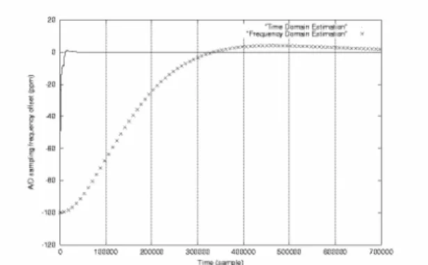
Fig. 4 shows A/D sampling frequency acquisitions of both estimations under the AWGN channel of 80 dB SNR. The given A/D sampling frequency offsets 100 ppm of the D/A frequency. The TDE takes only 5 DMT symbols while the FDE takes over 150 symbols to reach the requirement of 2 ppm jitter tolerance. Giving the same A/D sampling frequency offset, Fig. 5 shows RMS errors of the compensated A/D sampling frequencies in the steady state. Under AWGN channels, the TDE gains 20 dB SNR performances over the FDE. The advantage of the proposed TDE is to quickly depress the propagating sampling jitter.
Fig. 5 also shows that even the condition is the AWGN along with the twisted pair channel model (1000 ft.), the TDE gains 15 dB SNR performances over the FDE. ISI caused by the channel dispersion degrades jitter performances. The TDE loses 10 dB and the FDE loses 5 dB when the given SNRs are less than 60dB and 80dB respectively. The disadvantage of the TDE is the sensitivity to ISI. When the given SNRs are higher than the two corner values, the ISI contributes the noise floor and clips the jitter performances of both estimations.
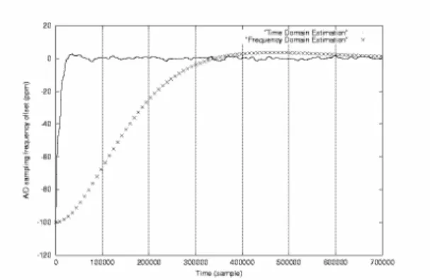
Fig. 6 and 7 show A/D sampling frequency acquisitions of both estimations over 1000 ft. and 3000 ft. VDSL transmission environments, and Fig. 8 shows A/D sampling frequency RMS errors of both estimations in the steady state under different channels. In the 1000 ft. case, the RFi and the FEXT dominate the noise floor for the TDE while only the FEXT influences the FDE due to fine pilot assignment. The proposed TDE possesses high speed acquisition and good jitter performance over the FDE. In the 3000 ft. case, the FEXT power decreases, but the ISI and the channel attenuation degrade jitter performances of the TDE.
Fig. 4. A/D sampling frequency acquisitions under AWGN channels of 80dB SNR. (Axis X represents the time domain, 1 symbol = 8832 samples.)
Fig. 5. A/D sampling frequency RMS errors vs. received signal SNRs under either AWGN channels or the AWGN with a 1000 ft. twisted pair (TP) channel model.
VI. CONCLUSIONS
This paper presents a time domain sampling frequency offset estimation method for DMT systems. When this method performs in VDSL systems under practical transmission environments, the timing recovery improves the acquisition speed more than 10 times of the pilot-aided frequency domain estimation method. And the jitter performances lead a gap for 1000 ft. transmission range and keep the same level for 3000 ft. range. Although this algorithm is sensitive to ISI, the proposed time domain estimation can avoid the failure of the timing recovery when the RFi hits pilots. Since this algorithm takes the advantage of the CP in DMT symbols, the estimation method can be applied to orthogonal frequency division multiplexing (OFDM) and single carrier modulation using frequency domain equalizer (SC-FEQ) systems.
REFERENCES
[1] J. Bingham, “Multi-carrier modulation for data transmission: an idea whose time has come,” IEEE Communications Magazine, vol. 28, no. 5, May 1990, pp. 5-14.
[2] ANSI T1.413, “Network and customer installation interfaces: asymmetric digital subscriber line (ADSL) metallic interface,”
American National Standards for Telecommunications, June 12,
1998.
[3] Working Group T1E1 (DSL Access), “Very-high bit-rate digital subscriber lines (VDSL) metallic interface,” Vancouver, Canada, February 2000.
[4] T. Pollet and M. Peeters, “Synchronization with DMT modulation,”
IEEE Communications Magazine, April 1999, pp. 80-86.
[5] R. E. Best, Phase-Locked Loops, 3rd ed., McGraw-Hill, 1998. [6] C. C. Chang, M. S. Wang, and T. D. Chiueh, “Design of a
DMT-based baseband transceiver for very-high-speed digital subscriber lines, ” IEEE Asia-Pacific ASIC Conference, Taipei, Taiwan, Aug. 2002, pp. 367-370.
[7] C. C. Chang, M. T. Shiue, and C. K. Wang, “ A VLSI architecture of DMT based transceiver for VDSL system, ” IEEE Asia-Pacific ASIC
Conference, Taipei, Taiwan, Aug. 2002, pp. 363-366.
[8] M. Sliskovic, “Carrier and sampling frequency offset estimation and correction in multicarrier systems,” IEEE GLOBECOM, Nov. 2001. [9] D. J. Rauschmayer, ADSL/VDSL Principles, MTP, 1999.
Fig. 6. A/D sampling frequency acquisitions over 1000 ft. transmission range.
Fig. 7. A/D sampling frequency acquisitions over 3000 ft. transmission range. 0.0001 0.001 0.01 0.1 1 AWGN AWGN+TP 1000 ft. 3000 ft. Channel A /D s am pl ing fre que nc y R M S error (ppm )
Time Domain Estimation Frequency Domain Estimation
Fig. 8. A/D sampling frequency RMS errors for different channels, including the AWGN of 80dB SNR, the AWGN with a 1000 ft. TP channel model, 1000 ft. transmission range, and 3000 ft. transmission range.