167
The Chip Design of A 32-b Logarithmic Number
Svstem
Sheng-Chieh Huang and Liang-Gee Chen' Department of Electrical Engineering
National Taiwan University Taipei, Taiwan 10764, R.O.C.
(886)-(2)-3633174 ext 443 [email protected]. ntu. edu.tw
ABSTRACT
To design a 32-bit logarithmic number system (LNS) processor, this paper presents two novel techmques : Digit-Partition (DP) to design log,{l.x) function and Iterative DBerence by Linear Approximation (IDLA) to design 2k function. The experimental result reveals that the proposed design is more attractive than the previous researches in the LNS processor.
I. MOTIVATION
The central issue addressed by the previous LNS processors is the implementation of the functions log,( 1+2") and log,( 1-2"). Conventionally, both functions log2( 1+2") and log2( 1-2") are implemented through methods of bit-serial [l]. range reduction, table look-up b d mathematical approximation [2] [3]. However, they suEer either speed degradation or large c h p a r e a cost when a high-precision design is desired. Only a few chip implementations of LNS arithmetic have been reported so far. An 20-bit LNS processor [2] is proposed to minimize this table complexity using a partitioned ROM and a PLA to acheve 12 bits fractional precision. Recently, a 30-bit LNS processor with 20 bits of fractional precision is reported in [3], which proposed a new algorithm for linear approximation using Merent-sized approximation intervals in each of a number of segments. To provide a hgher precision, the hybrid number system
(HNS)
[4] hasbeen introduced to perform logarithmic operations with 32-bit IEEE 754 single-precision floating-point
data
format. Anyway, the c h p area may be too large to implement in a single chp.In thls paper, we design a logarithmic number system (LNS) processor, by two new techniques, Digit-Partition (DP) for log,(l.x) design and Interactive DBerence by
Linear Approximation (IDLA) for 2k design. The basic concept behind the design of log,{l.x) is that the wordlength of x is Qvided into two parts to be implemented. Thus, ROM or PLA table can be reduced to
*now is Research Ccumltat m AT&T Bell Labs. Muny W. NJ This work was supported by Natimal Science Council under Grant NSC
824404-E-002-218
Thou-Ho Chen
Department of Electronic Engineering Nan-Tai College
Tainan, Taiwan 10764, R.O.C.
a reasonable size and t h s will make a high-precision design allowable. To design function 2k by IDLA, only adder, shifter, and a small PLA are required, unllke the previous designs which require ROM, and multiplier. Total hardware cost can be reduced, but it incurs a sacnfce of speed performance. To overcome this problem, the pipeline scheme is introduced. By using the proposed design of log,(l.x) and 2k, the loganthmic a t i o n , log,(1+2"), and subtraction, l0g2(l-2'), can be performed with large number of bits.
11. METHODOLOGY
In the LNS, a number x is represented by its sign and its logarithm to some base b. In this paper, we assume b = 2.
To represent a floating-point number, the representation of zero should be considered. For simplicity, zero is represented by using a zero flag
Z,.
Therefore, the numberx is now represented by the triple
a,,
Z,,
e,>, and is shownas
x = (1-z")x(-l)s~x2e~ (1) Formally, e, is an N bit fixed-point number with 1 integer bits and F fractional bits of precision, and N = F
+
1. Based on matchng withIEEE
single precision floating-point format, (1) can be rewritten aswhere M, is the 23-bit mantissa and log,(hfx ) has F bits and E, has I bits with a bias of execess-(2'-'- 1).
x = (l-z,)x(-1)srx2~+l+l0g~~~ ( 2 )
A. Primitive Arithmetic Operations LNS will be described in the following.
Ignoring signs, those basic operations performed in the Multiplication :
2" = a x b a c = E,+ log,(hfJ f Eb -t log,(hf&
Division :
Addition : 2"= a+b 3
2" = a/b 3 c = E, + lOg,(hfJ
-
{ Eb + lOg,(iMd )c = (E,
+
log,~J)+log,( 1 +2Eb+10g1(Ma)-(Ea+'0w'1
= (E,+lOg,(hfJ)tF+ (Eb+log,(hf&-~a'log,(hfJ)) Subtraction :
168
In the addtion and subtraction, we define the auxiliary functions F+(z) and F-(z)
as
log,(1+23 and log,(l-23, respectively, where z is an unsigned integer. Exponent operation in the floating-point number system consists of multiple multiplications. In LNS, only one multiplication is required. Besides, the multiplier can also support other functions in the LNS processor.B. Digit-Partition (OP) steps and described as follows :
The algorithm of digit-partition is composed of three
DP Algorithm Step 1 : Digitalization
log,(l.x) = 0.y
2 log,(l.xfi,x ,... X ] J = 0.ya ry2...y1, (3)
3 log,(l.x$]X,...x2J = 0.y#J.+.yz2 (4)
In the point of designing, it is intractable to implement equation (4) directly with ROM or PLA due to its large size, about 2” words. Based on the experimental results, if both values of x s p x,...x12 in (3) and (4) are identical, both values of y#fi2..yI, are also the same. In other words, log,( 0.00.. .xlplpls.. .x2J only dominates 0.00.. . Oy1y1$,, . .yZ2 value, not includmg 0.yaa2 ..y,,.
Step 2 : Dividing I.X$&. . .x22 = 2°3$1y2.,y”
I
( 5 ) - ~ (20.Yd’iYr-Y1 I ( 20.000... W Y I ~ Y I T . . Y ~ ~ )*( 2 4 Y # ~ * . ; y ” ) = 20.000...0OY1~1,..Yzz I 2”‘ 22 2 (1.X$/X2 ... xlJ * ( 2 - 0 , y g 1 y 4 1 )+
( 0.000 ... OX]^] &... x,,)* (6) In equation (6), ( l.xfi~~..x1,)*(2~0;y”y”y”.;yII) term can be obtained by using a 13-bit PLA with input xsp2..xI2. be derived by the Zog,(x) and 2” function as follows:(2-0.YQYLs~-Y11 ) = 20.000...0or,zY1*..Y22
Another term, (0,000..
.
O x , p I ~ , , . . .x,J*( 2-o yglyz-yll ), can(0. 000 ... ox/plpls..x2J*( 2-O9,+!9=+,11 ) -
- pga((O.OOO ...(tr,$,r,,.. x a 3 ‘ ( 2 -oyoYGJ2 Y I t ) )
~ p g i ( 0 . OOo... miziri,...xaJ+(-OY$~Yr ..YII)
-
- p g a ( o . X i $ l r ‘ i ~ - X a a ) + 6/11) + @Y$&’*..+’II)
(7) By using equation (6), (7) can be rewritten as
( 1 . X $ & . . . X I 2 ) * ( 2-O.y$92.91, ) +
p g a ( o ~ x i $ i # 1 ~ ~ ~ a a + (-13) + ( - 0 Y o ~ i ~ z ..YI I ) = 20.000.. . O m 1 zYiT-~aa
3 ( l . x $ ] x ~ . . x l , ) * ( 2-0yoyLy+41 ) +
(8) In equation (8), 2-13 means the 13 bits right s M i n g , and representation 2 - I F where 2” can be realized by the I bits
right shifting and 2-aF can be realized by function unit
( 2 - / 3 ) ( p g i ( o . x l $ i ~ i s - . x a z ) + (-O.V$flr..Yir) ) = ~ O . ~ O O . . . ~ ~ Y I ~ Y I ~ . . Y ~ ~
Step 3 : Group-Merging
~ ~ a ~ ~ l d l r ’ i s . ~ ~ x l ~ + ( - O ~ ~ l ~ r ~ ~ l l ) is transformed into another
(2a”) as described in the next section. To derive
with small chip size, the mapping ratio
[2] and DGPLA [ 5 ] techniques are introduced.
20.000...00v,zv,~..yzz
C. Iterative Difference by Linear Approximation (IDLA)
In the design of commercial product, 2a” is computed by
using the polynomial approximation and the following function.
P = ( P 2 + l ) ( P ‘ 1 - 1 ) + 1 = ( ( 2 Q ” ” - 1 ) + 2 ) ( 2 ~ 1 2 - 1 ) + 1 ( 9 )
By using the above equation, it can reduce the parameter range about haK Although, an additional multiplier is required. Besides, using the polynomial approximation will degrade the speed performance due to iterative multiply operations.
To overcome the above drawbacks, we propose a novel algorithm, called Iterative DiEerence by Linear Approximation (IDLA), to compute 2ax. The basic concept behind t h s algorithm is that the function 2a” can be o h n e d approximately through iterative linear approximations. The slope can be tuned to function
2,
where I is integer. Thus, only the adder and s M e r are required to implement 2&. E the Merence d,(x) between2’” and linear function y,, i.e. d,(x) = 2a“ - y,, is more than the permissible error, the next linear approximation operation should be presented as d,,(x) = d,(x) - y]. Such iterative linear approximations must be continued until the precision requirement is achieved. The IDLA algorithm can be described as follows :
IDLA Algorithm
step 0 : Let fix) = 2a”, 0
<
0.x < 1step 1 : Splitting f(x) into
2““
subsections, and i-th subsection is denoted asL(x), as shown in Fig.l(a), and 0
<
i I YO-1 where no is a positive integer.step 2 : Using linear approximation to obtain value off(x)
at each subsection x(x).
Let the difference between
L(x)
and its linear approximate function y, = m,x+
k, to be d,(x) = x(x)-
y i , and d,,- is the maximum value of d,(x)step 3 :
IF
Id,,-/ > Er ( i.e. the permissible error ) THEN splittingx(x) into2“‘
subsections, each subsectionis denoted asf;,(x), 0 2 j 2“‘-1 ELSE
goto step 6
at each subsection&(x) Lety,=m)c+k,, 0 5 js2”‘-1
d,(x)
=A@)
-
y, , d , - is the maximum value ofstep 4 : Using linear approximation to obtain value of d,(x)
d,W
step 5 :
IF
I
d , ,1
> Er THENsplitting d,(x) into 2”’ subsections, and then goto step 4 to judge each subsection again
goto step 6 ELSE
169
step 6 : Return f(x) = Z((m7
+
k J of each iteration)In the above algorithm, the permissible error E, is defined accordmg to the precision requirement. For the purpose of using only the adder and shifter to implement 2ax, m , is selected as 2.' or 1-2-', where I is an integer, if m ,
approximates 0 or 1, respectively. The selection of k,
depends on the following two cases ofL(x): Case 1 : As shown in Fig. l(b).
L, : y = m 7 + A , L , passespoint P
L, : y = m 7 + k, , L, passes tangent point Q of
A(x) and is parallel with L, the desired line is y = m 7 + k, , k, = (A
+
kJ/2 , where L , , L, and the desired line are all parallel Case 2 : As shown in Fig. l(c).L, : y = mF
+
A , L, passes point P L, : y = m 7 f B , L, passespoint Qthe desired line is y = m;z +k, , k, = (A +B)/2 , where L, , L, and the desired line are all parallel D. log,(l +.T) and log,(I-.T)
If x is normalized, log,(x) can be replaced by log,( 1 .x) in order to append one bit of precision and 2" is replaced by
2ax. Thus we firstly build circuits of function log,( 1 .x) by
DP and 2& by IDLA and then both are utilized to perform The derivation of log,(1+2") algorithm is composed of three parts. Firstly, under satisfvlng the precision requirement, the parameter range can be reduced to a smaller interval. In this interval, we utilize the essential zero and linear equivalent methods to derive the lower bound threshold and upper bound threshold, respectively. Secondly, l+2" is transformed to another form, i.e., 1+2" = 1+2'.F = 1+(25(2aF) when x 2 0 , and 1+(2-')(2-aF) when x < 0. 2' and 2.' will be implemented
by
s M e r , and 2aF and 2-0.F will be realized as described in the above subsection. Nevertheless, when x 2 0, the range of 1+2" will become very large after s m i n g 2aF left by I bits. Finally, to reducing the range, 10g,(1+(2')(2~3) is written as I+
log,(2*' +2aF) and now 2" is realized by addmg one to the i-th position of 2aF. When x < 0, 10g,(l+(2-')(2-~~)) can be implemented dlrectly by the log,( 1 .x) function since it has a small range, i.e., 1.5 < 1+(23(2-aF)
<
2. For 10g2(1-2'), there is the same discussion as that of log,(l+Y).log,( 1+2") and log,( 1-2").
III.
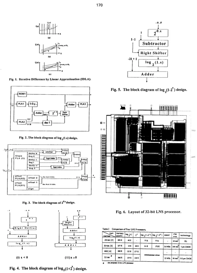
CHIP IMPLEMENTATIONFor brevity, the chip design of 32-bit LNS processor can be decomposed into four parts : log,(l.x), 2"', log,(1+2"), and log,(l-2"). For log,(l.x), the core hardware consists of one 8192 x 12 b ROM, three PLAs (sizes of PLA1, PLA2 and PLA3 are 15850 b, 11400 b and 14380 b) , two adders (adderl: 13-b and added: ll-b) and one 24-b shifter as
shown in Fig. 2. Fig. 3 shows the block diagram of 2h design and the core hardware consists of two PLAs (size of
slope PLA is 9536 b and size of offset PLA is 117435 b), one 24-b shifter and four 23-b adderdsubtractors. The core hardware of log,( 1+2"), and log,( 1-27 consists of functional units 2aF and 2-aF, as described in Fig. 4 and Fig. 5 , respectively.
The chip of 32-bit LNS processor is completed
by
using the structural silicon compiler in Genesil system with TSMC 0.8pm technology. The chip size is 90 mm2 and it can be operated at 25 M H z . Fig. 6 shows layout of the chp.The proposed 32-bit LNS processor will be compared with three previous LNS processors in terms of the bit
number, look-up table size, speed, and c h p area, as
illustrated in Table I.
IV.
CONCLUSIONSThis paper proposes the &git-partition (DP) technique to design log,(l.x) function and Iterative Difference
by
Linear Approximation (IDLA) to design 2& function with high precision. By DP, log,(l.x) with large bit number of xcan be achieved with moderate hardware cost. By IDLA, we can design 2°, function with only adder and shifter. Thus, the logarithmic addition log,(l+2") and subtraction log,(l-2") can be realized with the proposed log,(l.x) and 2h, to acheve a high-precision capability. Based on the proposed 32-bit LNS processor whch satisfies the IEEE 754 standard, we hope that the digtt partition and IDLA techntque will be further applied to the higher precision number system while showing cost-effective and high-precision design in the future.
REFERENCES
H. Y. Lo, J. L. Chen, "A Hardwired Generalized Algorithm for Generating the Logarithm Base-k by
Iteration," IEEE Trans. Comput., vol. C-36, pp. F. J. Taylor, R. Gill, J. Joseph, J. Radke, "A 20 Bit Loganthmic Number System Processor,"
IEEE
Trans. Comput., vol. 37, pp. 190-200, Feb. 1988. Lawrence K.Yu, David M. Lewis, "A 30-b Integrated Loganthmic Number System Processor," E E E J. Solid-state Circuits, vol. 26, pp. 1433-1440, Oct. 1991.F.
S.
Lai, "The Architecture and Analysis of a Hybrid Number System Processor," IEEE Sym. on Circuit and System, pp. 803-806, 1992.H. Y. Lo, Y. Aolu, "Generation of a Precise Binary Loganthm with Difference Grouping Programmable Logtc Array,"
IEEE
Trans. Comput., vol. C-34, pp. 1363-1367, NOV. 1987.170 t... ' ?
...
.. -4 I S ) Ibl IC1Fig. 1. Iterrlive Difference by Linear Approximation (IDLA).
I
Pig. 2. The block dirgrmm of log,(l.x) design.
I
Fig. 3. The block diagrain of2"'deJign.
l
....
(i) x < 0 ( i i ) x 20
r
IIc/
Fig. 5. The block diagram of Iog2(l-ZX) design.
_ _ _ .
6
1
Fig. 6. Layout of 32-bit LNS processor
Table I Commrison of Fow LNS Pr-m