Well Aligned Half-V Ferroelectric Liquid Crystal in Asymmetrical
Surface Polarity Controlled Alignment Cells
Huang-Ming Philip Chen* and Chi-Wen Lin
Department of Photonics and Display Institute, National Chiao Tung University, Hsinchu, Taiwan,
30010 R.O.C.
ABSTRACT
Ferroelectric liquid crystals (FLCs) were known to possess fast response time under 1 ms. The low contrast ratio yielding from defect alignment, however, limited their display application. Based on FLC elastic free energy, the asymmetrical surface polarity controlled alignment was able to suppress the horizontal chevron defects in a half V-shaped switching FLC cell. It is due to the FLC's spontaneous polarization (Ps) pointed to one direction inducing by the opposite surface polarity in asymmetrical hybrid cell. The experimental approach of different alignment materials and different strengths of surface anchoring energies were evaluated in this study. The highest contrast ratio of 780:1 at saturation voltage under 5 V was obtained. The asymmetrical surface polarity controlled alignment technique provided a promising FLC well alignment and fast switching result for TFT-LCD application.
Keywords-Half-V mode FLC, ferroelectric liquid crystal, alignment defect, horizontal chevron defect
1. INTRODUCTION
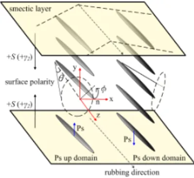
Ferroelectric liquid crystal (FLC) device was first realized by Clark and Lagerwall in 1980 [1]. They proposed surface-stabilized ferroelectric liquid crystal (SSFLC) with the distinctiveness of sub-millisecond response time and bi-stability, which had attracted great attentions to explore numerous applications in fast response optical devices. The high driving voltage, alignment defect, and lacking of continuous gray scales limit FLCs’ application for high resolution displays. In order to overcome the gray scales capability, many FLC modes were developed base on the analogue modulation of their optical axis [2-8]. Among these attempts, the half-V mode FLC (HV-FLC), possessing N*-SmC* phase sequence, provides the intrinsic continuous gray scales which is suitable for the driving using active matrix thin-film-transistor (AM TFT) as backplane [7-8]. However, the horizontal chevron alignment defect is the major drawback
which remains to be solved in HV-FLC devices. The defect is due to the FLC’s molecular spontaneous polarization (PS)
up and down domains are both presented under cooling process from its N*-SmC* phase [9, 10], as shown in Figure 1. The origin of the horizontal chevron alignment defect can be explained from the physical aspect of the FLC’s free
energy [11]. The total free energy per unit area of PS up and PS down domains can be expressed as in Eq. (1):
(
θ θ)
θ γ φ γ φ γ γ φ θπ sin sin cos sin ( sin sin ) ( )cos
2 () 2 ) ( 2 2 ) ( 1 2 ) ( 1 2 2 3 2 2 2 2 2 b t b t K K p d F= + + + m − (1)
Figure 1. The coordinate system of aHV-FLC cell.
The total free energy of H-V FLC is the summation of FLC’s elastic free energy, non-polar surface energy, and polar surface energy terms. A perfect model of uniform state can be expressed when all FLC’s spontaneous polarization fall into a uniform direction at the lowest free energy obtained by optimizing FLC’s pitch length (p), cell gap (d), cone
angle (θ), elastic constants (K), and the surface interaction coefficients (γ) [12]. The (-) and (+) signs are PS up and PS
down domains in the polar surface energy term presenting in the horizon chevron defect, respectively. The PS up and PS
down domains co-exist due to the same minimum total free energy in symmetric cell, which has the same polar surface
interaction coefficients, i.e. ( ) ( )
2 2
t b
γ =γ . As a result, a defect free alignment texture can be achieved when FLC’s
spontaneous polarization oriented itself at the same direction. In this study, the asymmetric alignment techniques were applied to control surface polarity [11] and the anchoring energy [13]. The difference of the polar surface energy term,
( ) ( )
2 2
(γ t −γ b ), holds the key to degenerate a lower level of FLC’s free energy in the asymmetric alignment surfaces (i.e.
( ) ( )
2 2
t b
γ ≠γ ) according to Eq. (1). Two approaches for asymmetrical alignment conditions: (1) change the sign of ( )
2
b
γ ,
which can be approached by opposite surface polarity; and (2) prepare the difference value between ( )
2 t γ and ( ) 2 b γ by
controlling the alignment strength.
2. EXPERIMENTS
H-V FLC materials, R2301 (Iso 86.8 N* 64.7 SmC*, Ps=4 nC/cm2, AZ Electronic Materials) and R3206 (Iso 109.9
N* 79.5 SmC* -17.9 Cr, PS=20.1 nC/cm2, V
sat. at 3.5V, AZ Electronic Materials) were utilized in this research. A series
of R3206H (Iso 110.7 N 73.8 SmC -29.7 C) was mixed into R3206 at different weight percentages to prepare R3206-0, R3206-80, R3206-70, and R3206-50. The cell gap was controlled by 1.5 μm spacer. The polar anchoring energy of
rubbed polyimide (PIA-X201-G01, Chisso) is in the order of 10-4 J/m2, and the plasma treated PI surfaces is 10-5 J/m2
[13]. The surface polarities of alignment layers were determined by the cross rubbed cell [14]. Positive surface polarity materials, such as poly vinyl alcohol (PVA), hexamethyldisilizane (HMDS), and Nylon 6 were applied. The negative surface polarity material, such as polyimide, was applied for the experimental comparison. The polarizing optical microscope (POM) pictures of each sample were captured with the magnifications of 100X. The spontaneous polarization was characterized by liquid crystal analysis system (LCAS-1, from LC Vision) under 5 µm pre-made cells (purchased from LC Vision).
3. RESULTS AND DISCUSSION
Most of liquid crystal cells are made of the same alignment material, such as polyimide. PS up and PS down domains
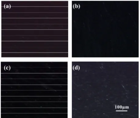
can coexist under symmetric alignment condition, as shown in Figure 1. The first attempt was change the direction of one surface polarity. LC alignment textures of H-V FLC materials, R3206-0, -80, -70, and -50, in the PI coated symmetric cells were captured under polarizing optical microscope (POM), as shown in Figure 2(a-d), respectively. The
opposite surface polarity alignment layers, PVA and PI, were use to prepare asymmetric cells.The horizontal chevron
defects of R3206-50 and R2301 were both eliminated in the PVA and PI hybrid cell, as shown in Fig. 3(a) and (b), respectively. The alignment of R3206-50 and R2301 were greatly improved by the asymmetric cells compared to the original symmetric cell structure. Furthermore, different alignment layers were utilized to verify surface polarity controlled in the asymmetric cell structure. Positive polarity alignment layers, such as HMDS and Nylon 6, were applied to assemble the asymmetric cell with PI. Both HMDS and Nylon 6 hybrid cells successfully suppressed the horizontal chevron defects of R2301 as shown in Fig. 3 (c) and (d), respectively.
(a) (b)
(c) (d)
100μm
Figure 2. Polarizing optical micrographs of (a) R3206-0, (b) R3206-80 (c) R3206-70, and (d) R3206-50 in the 1.8±0.1µm PI cells.
(a) (b)
(c) (d)
100μm
Figure 3. Alignment textures of (a) R3206-50 in PI-PVA cell; and R2301 in (b) PI-PVA cell, (c) HMDS-PI asymmetric cell, and (d) Nylon 6-PI asymmetric cell.
The surface polarity, γ , is able to be altered by different alignment techniques. By controlling the surface polarity 2
and polar anchoring energy, the ( ) ( )
2 2
(γ t −γ b) value was increased progressively under the asymmetric alignment
conditions from ( ( ) 2 t strong γ , ( ) 2 b weak γ ), ( ( ) 2 t strong γ − , ( ) 2 b weak γ ), to ( ( ) 2 t strong γ − , ( ) 2 b strong
The alignment abilities of asymmetric cells, PIrub-PIplasma (i.e. rubbed PI and plasma treated PI surfaces), PVArub-PIplasma,
and PVArub-PIrub with progressively increased (γ2( )t −γ2( )b) values, were evaluated by the alignment defects generated at
various cooling rate. Base on Eq. (1), H-V FLC molecules tend to align as mono-domain texture when increasing the
( ) ( )
2 2
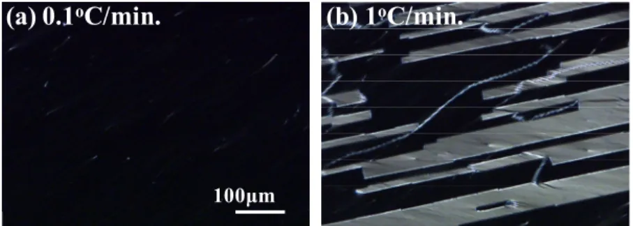
(γ t −γ b) value. Under the smallest cooling rate at 0.1 oC/min., the horizontal chevron defect was suppressed in the
asymmetric cell, as shown in Figure 4(a). The horizontal chevron defect was presented in the PIrub-PIplasma cell when the
cooling rate increased to 1 oC/min, as shown in Figure 4(b). Under the cooling rate at 2 oC/min., the light leakage
showed in the PVArub-PIplasma cell, as in Figure 5(b). The PVArub-PIrub cell, with larger difference in γ value, 2
appeared to have better molecular alignment than the other asymmetric cells, as shown in Figure 6(a-c). The tolerance
of cooling rate for PIrub-PIplasma, PVArub-PIplasma, and PVArub-PIrub asymmetric cells were 0.1, 1, and 3 oC/min.,
respectively. Among the all asymmetric cells, the PVArub-PIrub cell appeared to have the best alignment even under fast
cooling rate.
(a) 0.1
oC/min.
(b) 1
oC/min.
100μm
Figure 4. Polarizing optical micrographs of R3206-50 under different cooling rates in the PIrub-PIplasma cells.
(d) 1
oC/min.
(e) 2
oC/min.
100μm
Figure 5. Polarizing optical micrographs of R3206-50 under different cooling rates in the PVArub-PIplasma cells.
(a) 1
oC/min.
(b) 3
oC/min.
(c) 5
oC/min.
100μm Figure 6. Polarizing optical micrographs of R3206-50 under different cooling rates in PVArub-PIrub asymmetric cells.
The electro-optical properties were characterized with 100Hz square wave at different temperature. The threshold voltage of R3206-50 was 1.2 V and its saturation voltage was 4.5 V, as shown in Figure 7. The electro-optical responses
are temperature insensitive. The contrast ratio of R3206-50 in the PVArub-PIrub treated asymmetric cell was greatly
improved from 76:1 to 780:1. R3206-50 demonstrated fast response under 1.3 ms (τrise= 380 μs, τfall= 920 μs).
Figure 7. Voltage-transmittance curves of R3206-50 in the PVArub-PIrub asymmetric cell varied with temperature.
4. CONCLUSION
The asymmetrical alignment technique, i.e. ( ) ( )
2 2
t b
γ ≠γ , was proposed to solve the alignment defect issue in this
study. The asymmetrical alignment conditions were able to be achieved by controlling the surface polarities and
anchoring energies. By varying the different alignment surface conditions, PIrub-PIplasma, PVArub-PIplasma, and PVArub
-PIrub asymmetric cells, the value of the polar surface energy term, ( 2( ) 2( ))
t b
γ −γ , were progressively increased. The cooling
rate tolerance was found at 0.1, 1, and 3 oC/min for PI
rub-PIplasma, PVArub-PIplasma, and PVArub-PIrub asymmetric cells,
respectively. The PVArub-PIrub cell, which has the larger γ value differences, appeared to have the best alignment 2
result even under fast cooling rate. The contrast ratio was greatly improved to 780:1 with saturation voltage at 4.5 V in the asymmetric cell. This alignment technique provided promising FLC material, and processing feasibility for the fast switching TFT-LCD application.
5. ACKNOWLEDGMENTS
The authors are grateful for the financial support provided by National Science Council of the Republic of China under Grant No. NSC982A23 and Chimei Innolux Corporation. The polyimide was kindly provided by Chisso.
[2] H. Fujikake, T. Murashige, H. Sato, Y. Iino, M. Kawakita, and H. Kikuchi, “Flexible ferroelectric liquid-crystal devices containing fine polymer fibers” J. Soc. Inf. Display 10(1), 95-99, 2002.
[3] A. G. H. Verhulst, G. Cnossen, J. Fünfschilling, and M. Schadt, “A wide-viewing-angle video display based on the deformed-helix ferroelectric liquid-crystal effect and a diode active matrix” J. Soc. Inf. Display 3(3), 133-138, 1995. [4] J. S. Patel, “Ferroelectric liquid crystal modulator using twisted smectic structure” Appl, Phys. Lett. 60, 280 (1992). [5] D. W. Kim, E. Jang, Y. W. Lim, and S. D. Lee, “Defect-free deformed-helix ferroelectric liquid-crystal mode in a
vertically aligned configuration” J. Soc. Inf. Display 16(9), 947-952, 2008.
[6] E. P. Pozhidaev, M. V. Minschenko, O. A. Shadura, A. L. Andreev, and I. N. Kompanets, “Stability of hysteresis-Free Passively Adressed FLC Display with Inherent Gray Scale” SID Symposium Digest 38, 1078-1081, (2007). [7] Y. Asao, T. Togano, M. Terada, T. Moriyama, S. Nakamura and J. Iba, “Novel ferroelectric liquid crystal mode for
active matrix liquid crystal display using cholesteric-chiral smectic C phase transition material” Jpn. J. Appl. Phys. 38, 5977 (1999).
[8] T. Nonaka, J. Li, A. Ogawa, B. Hornung, W. Schmidt, R. Wingen and H. R. Dubal, “Material characteristics of an active matrix LCD based upon chiral smectics” Liq. Cryst. 26, 1599 (1999).
[9] T. Hatano, K. Yamamoto, H. Takezoe and A. Fukuda, “Alignment controls and switching characteristics in a ferroelectric liquid crystal with the phase sequence of N*-Sc*” Jpn. J. Appl. Phys. 25, 1762 (1986).
[10] J. S. Patel and J. W. Goodby, “Alignment of liquid crystals which exhibit cholesteric to smectic C* phase transitions” J. Appl. Phys. 59, 2355 (1986).
[11] H. M. P. Chen and C. W. Lin, “Free alignment defect, low driving voltage of half-V ferroelectric liquid crystal device” Appl. Phys. Lett. 95, 083501 (2009).
[12] T. C. Chieu, “Effect of material constants on the orientation structure of ferroelectric liquid crystal cells” J. Appl.
Phys. 64, 6234 (1988).
[13] C. W. Lin, C. Y. Hsu, and H. M. P. Chen, “Plasma alignment technology for liquid crystal devices”, IDMC 2009 (2009).
[14] K. Takatoh, H. Nagata, and T. Saishu, “Orientations and viewing angle dependence of twisted ferroelectric liquid crystal” Ferroelectrics 179, 173 (1996).