以廢輪胎碎片壓縮層降低側向土壓力
Reduction of Ear th Pr essur e with Tir e-chip Cushion
計 劃 編 號 : NSC 90-2211-E-009-069
執 行 期 間 : 90 年 8 月 1 日至 91 年 7 月 31 日
計畫主持人: 方永壽 國立交通大學土木工程研究所 教授
1. Abstr act
1.1 中文摘要
本研究探討以廢輪胎碎片壓縮層降低作用在靜止 擋土牆之側向土壓力。本研究以渥太華砂作為擋土牆 後之回填材料,利用國立交通大學靜止土壓力擋土牆 設備進行模型實驗。根據實驗結果,獲得以下各項結 論: (1)有壓縮層作用時,夯實影響區內所量到的側向 壓力大於 Jaky 預測值,但遠小於純砂回填夯實造成的 側向壓力。在夯實影響區下方的側向壓力會趨近於 Coulomb 主動土壓;(2)在夯實影響區內,壓縮層厚度 愈厚,降低側向壓力的成效愈顯著。為能有效降低側 向壓力,建議壓縮層厚度至少需 0.05H;(3)於 1.5 m 高的回填土狀況,與純砂回填夯實相較,70 mm 厚的 壓縮層可降低大約 41%的側向土壓合力。關鍵詞:
廢輪胎、
壓縮層、模型試驗、夯實、土壓 力、砂1.2 English Abstr act
This study presents the application of a tire-chip compressible layer to reduce earth pressure against a non-yielding wall. Ottawa sand was used as a backfill material. The NCTU non-yielding wall facility was used to conduct all earth-pressure experiments in this study. Based on this study, the following conclusions can be drawn: (1) With the compressible layer, the lateral pressures measured in compaction-influenced zone were still higher than Jaky’s solution. However, the magnitude of the compaction-induced pressure was much less than that without the compressible layer. Below the compaction-influenced zone, the lateral pressures tend to converge with Coulomb active earth pressure; (2) In the
compaction-influenced zone, the thicker the
compressible layer is, the more compaction-induced pressure will be released. To effectively reduce the earth pressure acting on the non-yielding wall, it is
recommended that the thickness of the compressible layer should be at least 0.05H; (3) For 1.5-high backfill with a 70 mm-thick compressible layer, about 41% of the total soil thrust had been reduced than that measured without the compressible layer.
Keywor ds
: Tir e-chip, Compr essible layer, Model test, Compaction, Ear th pr essur e, Sand2. Intr oduction
Based on the information from the Environmental Protection Administration of the R.O.C. government, more than 40% of the discarded trash were recoverable. Scrap tires were very important among the recoverable discard, because the main component of tires is rubber, which is a valuable natural resource. Currently, most scrap tires are land-filled or stockpiled. However, this used valuable landfill space, creates potential fire hazard, and provides a breeding ground for mosquitoes. Traditional treatments for scrap tires are not economical, and may induce hazards to health and environment. In recent years, the used of scrap tires by cutting into small pieces or chips for civil engineering application has increased. The tire chips or tire shreds were used mostly as backfill of embankments and retaining structures. Using tire chips or shreds as backfill material has several potential benefits. In areas where the underlying soil is weak or compressible, the low unit weight of tire chips would apply a smaller vertical stress than the conventional backfill leading to lower settlement and increased global stability for the underlying soil. The horizontal stress induced by the lightweight fill on the retaining structure would be lower than that induced by the conventional backfill, resulting a less-expensive retaining wall design. Moreover, high permeability of tire chips would provide good drainage, and reduce lateral thrust due to the hydrostatic pressure behind
retaining wall.
In most literatures, the applications of tire chips are associated with lightweight backfill. The potential problems for using tire chips as backfill are large compressibility and settlement. Humphrey et al. (1993), Ahmed and Lovell (1994), Bosscher and Edil (1994) reported that, the amount of compressibility due to tire-chip backfill was up to 30 %. Because tire chips are highly compressible, in this study tire chips are used as a cushion layer between the non-yielding wall and backfill. The lateral earth pressure pushes the tire-chip cushion to compress. Thereby the active wedge could be developed and then the at-rest earth pressure could be reduced. To obtain a better understanding of the topics discussed above, experiments were conducted with the National Chiao Tung University (NCTU) non-yielding model wall facility. This system is capable of measuring earth pressure with soil pressure transducers mounted on the model wall. The tire-chip cushion layer is placed between the NCTU non-yielding model wall and Ottawa backfill. According to the test results with cushion layer, it can be investigated total lateral thrust acted against the wall, the distribution and variation of lateral earth pressure, and location of the total thrust for backfill. Test results will also be compared with Jaky’s formula and Coulomb active earth pressure coefficient.
3. NC T U M od el R et a in in g W a ll Fa cilit y
The National Chiao Tung University (NCTU) model retaining wall facility can be divided into three main parts: (1) soil bin; (2) model retaining wall and (3) data acquisition system. The soil bin is 1500 mm in length, 1500 mm in width and 1600 mm in depth. Both side-walls and end-wall of the soil bin are made of 35-mm thick solid steel plate and welded carefully to ensure its structural integrity. The bottom of the soil bin was covered with a layer of SAFETY WALK to provide adequate friction between the soil and the base of the bin. To constitute a plane strain condition, the soil bin is built very rigid so that lateral deformations of the side-walls will be negligible. The friction between the backfill and the side-walls is to be minimized. This is accomplished by creating a lubrication layer between the side-walls and the soil. The lubrication layer consists of 2 0.009-mm thin plastic sheets and a 0.152-mm thick plastic sheet. The measured friction angle is about 7.5°.The model wall shown in Fig. 1 is 1.5 m-wide, 1.6 m-high and 45 mm-thick and made of a solid steel plate.
Sixteen strain-gage-type transducers (Kyowa
PGM-02KG, capacity = 19.6 kN/m2) were arranged within the central zone of the wall to avoid the friction that might exist near the side-walls of the soil bin. To simulate field condition, a vibratory soil compactor had been used to densify the backfill. An eccentric motor (KJ75-2P) manufactured made by Mikasa had been selected to be the source of vibration. The eccentric force of the motor could be controlled by adjusting the number of eccentric plates in the motor. Due to the considerable amount of data collected, all the signals generated by the earth pressure transducers are processed by a data acquisition system.
4. Backfill, Compressible Layer and Inter face
Char acter istics
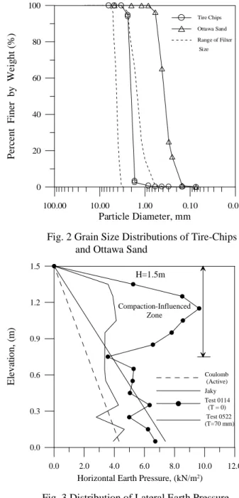
In this study, the dense Ottawa sand with a unit weight of 16.43 kN/m3 was used as backfill and the internal friction angle of the backfill would beφ = 39.6o, the wall friction angle would be δ = 13.1o. The compressible layer was made by fills of tire chips into a geotextile bag. The bag is 1.5 m-wide, 1.5-m high, and the thickness of the compressible layer was a parameter to investigate. The bag was sewed with polyester continuous filament non-woven geotextile and tire chips were used to constitute the compressible layer due to its high compressibility. Grain-size distribution of the rubber particles was indicated in Fig. 2. Major factor considered in choosing the particle size is to regard the tire chips as a filter material to protect Ottawa sand. One-dimensional compression tests were conducted to investigate the relationship between the vertical pressure and strain of tire chips. Experimental results show that under the vertical pressure of 10 kPa, the vertical strain measured was up to 25 %.
5. Exper imental Results
Air-dry Ottawa sand was shoveled from the soil storage into the soil hopper, then pluviated into the soil bin for a thickness of about 0.35 m. The surface of the first layer backfill was carefully leveled to form a flat surface. The loose backfill was divided into 6 lanes and compacted. Each lane was densified with the soil compactor for a pass of 70 seconds. The thickness of the
compacted lift is about 0.3 m. Repeat the above procedures until the height of backfill accumulated up to 1.5m. Thickness (T) of the compressible layer adopted in the experiments include: no compressible layer, 20 mm, 40 mm, 70 mm, 120 mm, 180 mm, and 250 mm.
The solid symbol in Fig. 3 shows that horizontal earth pressure distribution for a 1.5 m-high backfill without the compressible layer (T=0). It is obvious that the pressure distribution is nonlinear. Extra-high lateral pressure was observed near the top of the backfill. The horizontal earth pressures increased substantially from 0 to 0.75 m below soil surface, and the peak value was reached at 0.35 m below soil surface. This high-pressure zone
developed due to compaction is defined as
“compaction-influenced zone”. The earth pressure due to compaction has been investigated by Rowe (1954), Sherif et al. (1984), Duncan and Seed (1986), and many other researchers. Duncan et al. (1991) developed charts to estimate the compaction-induced earth pressure quickly and reliably. In this study, the peak earth pressure induced by compaction was about 10 kN/m2. It was much larger than Jaky’s solution. However, below the compaction-influenced zone, lateral earth pressure distributions was in fairly good agreement with Jaky’s solution.
The hollow symbol in Fig. 3 shows horizontal earth pressure distribution due to a 1.5 m-high backfill with a 70-mm-thick compressible layer (T = 70 mm). In the
figure, the lateral pressure measured in the
compaction-influenced zone was higher than the Coulomb active and Jaky solution. However, the magnitude of compaction-influenced pressure is much less than that without the compressible layer. Below the
compaction-influenced zone, the lateral pressure
distribution measured for the test with a 70 mm-thick compressible layer tends to converge with the Coulomb active earth pressure. It would be reasonable to expect the tire chips to compress more near the base of the wall, because the lateral pressure is a function of depth. It is obvious in Fig. 3 that the tire-chip compressible layer is an effective material to reduce lateral earth pressure acting on the non-yielding retaining wall.
As compared with the case without the compressible layer, the tire-chip layer has effectively reduced the total soil thrust. For the 1.5 m-high backfill, the coefficient Kh
measured with a 70 mm-thick compressible layer is about 0.30. This value is about 41% less than the coefficient Kh obtained without the tire-chip layer. This
value is even less than the at-rest coefficient K0
determined with Jaky’s formula. However, due to the remaining compaction-induced earth pressure, Kh = 0.30
is about 50% greater than the active coefficient Ka
determined with Coulomb theory. The coefficient Kh is
defined as the ratio of the horizontal total thrust Ph to γH2
/ 2. The total thrust Ph is calculated by summing the earth
pressure acting on the wall.
The variation of soil thrust coefficient Kh with T/H for
a 1.5 m-thick backfill is shown in Fig. 4. When T/H reached about 0.12, the value of Kh would reach a
constant value of about 0.28. It is recommended that, to effectively reduce the earth pressure acting on the non-yielding wall, the thickness of the compressible layer should be at least 0.05H.
6. Conclusions
This study investigates the application of a tire-chip
compressible layer to reduce lateral earth pressure acting on a non-yielding wall. Based on the experimental work, the following conclusions can be made. (1) Soil compaction will induce high lateral pressure near the top of the backfill. The lateral pressures below the compaction-influenced zone tend to converge with Jaky’s solution. (2) With the compressible layer, the lateral pressures measured in compaction-influenced zone were still higher than Jaky’s solution. However, the magnitude of the compaction-induced pressure was much less than that without the compressible layer. Below the compaction-influenced zone, the lateral pressures tend to converge with Coulomb active earth pressure. (3) In the
compaction-influenced zone, the thicker the
compressible layer is, more compaction-induced pressure will be released. To effectively reduce the earth pressure acting on the non-yielding wall, it is recommended that the thickness of the compressible layer should be at least 0.05H. (4) For 1.5-high backfill with a 70 mm-thick compressible layer, about 41% of the total soil thrust had been reduced than that measured without the compressible layer.
7. References
Lightweight Geomaterials,” Transportation Research Record 1422, pp. 61-70.
2.Bosscher, P. J. and Edil, T. B. (1994), “ Engineering Properties of Tire Chips and Soil Mixtures”, ASTM Geotechnical Testing, pp. 453-464.
3.Duncan, J. M., and Seed, R. B., (1986),
“Compaction-Induced Earth Pressures under
Ko-Conditions,“ Journal of Geotechnical Engineering,
ASCE, Vol. 112, No. 1, pp. 1-22.
4.Duncan, J. M., Williams, G. W., Sehn, A. L., and Seed, R. B., (1991), “Estimation Earth Pressures Due to Compaction,” Journal of Geotechnical Engineering, ASCE, Vol 117, No. 12, pp. 1833-1847.
5.Humphrey, D. N., Sandford, T. C. and Cribbs, M. M., (1993), “Shear Strength and Compressibility of Tire Chips for Use as Retaining Wall Backfill,” Transportation Research Record 1422, pp. 29-35
.
6.Rowe, P. W., (1954), “A Stress Strain Theory for Cohesionless Soil with Applications to Earth Pressures At Rest and Moving Walls,” Geotechnique, Vol. 4, pp. 70-88.
7.Sherif, M. A., Fang, Y. S., and Sherif, R. I., (1984), ”Ka
and Ko behind Rotating and Non-Yielding Walls,”
Journal of Geotechnical Engineering, ASCE, Vol. 110, No. 1, Jan., pp. 41-56.
Fig. 1 NCTU Non-Yielding Retaining Wall
0.01 0.10 1.00 10.00 100.00 Particle Diameter, mm 0 20 40 60 80 100 P er ce n t F in er b y W ei g h t (% ) Tire Chips Ottawa Sand Range of Filter Size
Fig. 2 Grain Size Distributions of Tire-Chips and Ottawa Sand
0.0 2.0 4.0 6.0 8.0 10.0 12.0
Horizontal Earth Pressure, (kN/m2)
0.0 0.3 0.6 0.9 1.2 1.5 E le v at io n , (m ) Coulomb (Active) Jaky Test 0114 (T = 0) Test 0522 (T=70 mm) H=1.5m Compaction-Influenced Zone
Fig. 3 Distribution of Lateral Earth Pressure
H = 1.5m 0.0 0.1 0.2 T / H 0.0 0.2 0.4 0.6 0.8 1.0 Kh Jaky Coulomb Active