行政院國家科學委員會專題研究計畫 成果報告
以步階阻抗諧振器設計密集化低階與高階橢圓函數濾波器
計畫類別: 個別型計畫
計畫編號: NSC93-2213-E-009-095-
執行期間: 93 年 08 月 01 日至 94 年 07 月 31 日
執行單位: 國立交通大學電信工程學系(所)
計畫主持人: 郭仁財
報告類型: 精簡報告
報告附件: 出席國際會議研究心得報告及發表論文
處理方式: 本計畫可公開查詢
中 華 民 國 94 年 10 月 31 日
Design of Two-Stage UIR and SIR Bandpass Filters
with an Elliptic Function-Like Response
Jen-Tsai Kuo, Wan-Hsin Hsieh and Meshon Jiang
Department of Communication Engineering
National Chiao Tung University, Hsinchu, 300, Taiwan
Abstract — Compact bandpass filters with a sharp transition band are presented. The circuit consists of a cascade of two stages. The cascade is implemented by a direct coupling scheme, as well as a three-line structure. Each stage is a resonator tapped with a quarter-wave open stub at its center and a transmission zero can be created. The positions of the two zeros can be easily tuned to locate close to the passband, so that an elliptic function-like response can be obtained. Both uniform impedance resonators (UIRs) and stepped impedance resonators (SIRs) are employed. Experimental results show a close agreement with the design.
Index Terms — Elliptic filters, microstrip filters, transition band, transmission zero, stepped impedance resonator.
I. INTRODUCTION
Filters are essential components in the RF front end of a wireless communication system. Planar filters are usually preferred due to its low cost, good reliability and ease in synthesis and design. A high-performance planar microwave filter is usually required to have a good attenuation level in rejection bands and a sufficiently wide upper stopband. It is especially favorable that transmission zeros can be created and easily tuned close to the passband, since one of the important missions of a filter is to suppress the image frequency near the passband. The creation of transmission zeros in a planar filter can be achieved by establishing proper cross couplings [1-3], tapping input/output resonators [4,5], and employing a zero degree feed scheme [6].
In [7], quarter-wave microstrip resonators are proposed to design a compact and low loss filter with elliptic-type performance. In this filter, two transmission zeros are generated at upper and lower sides of the passband. It is found that strong couplings between feed lines and end resonators are required in the structure, so that a very small coupling gap becomes inevitable.
In this presentation, uniform impedance resonators (UIRs) and stepped impedance resonators (SIRs) are employed to design a bandpass filter with a sharp transition band. The sharp transition band is achieved by
locating transmission zeros close to the passband. Both the UIRs and SIRs are tapped with an open stub at its center. When the stub is longer than a quarter wavelength at the design frequency, a transmission zero at lower passband edge is introduced to the filter, and vice versa. A cascade of two filter stages, one of them has a transmission zero at the lower edge of the passband and the other has a zero at the upper edge, forms a bandpass filter with sharp transitions. In addition to direct coupling of the two stages, three-line microstrip structures [8] are also incorporated into the design.
W2 W1 l2 l2 l1 1 l ls
Fig. 1. Structure of two tapped quarter-wave SIRs.
Frequency (GHz) 2.4 2.2 2.0 |S | (dB ) -60 -70 -50 21 -30 -40 -20 3.0 2.8 2.6 0 -10 fo fp fz
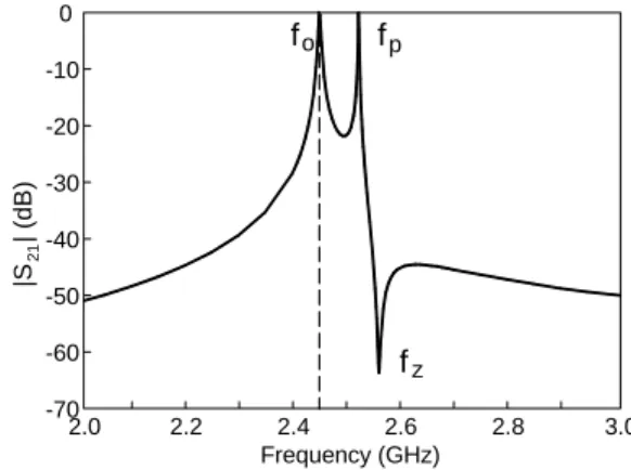
Fig. 2. The transmission zero and poles of a tapped SIR. Structure parameters of the SIR, l2/l1 = 2 and Z2/Z1 = 0.3.
3.4 2.2 0.8 0.9 1.0 1.1 2.8 Frequ ency (GHz) 2.4 2.6 3.0 3.2 1.2 3.6 fp o f z f s l /(λ/4) (a) 3.1 Fre que ncy (G H z ) 1.2 1.1 1.0 0.9 0.8 2.3 2.1 2.5 2.9 2.7 3.3 l s/(λ/4) o f fp z f (b)
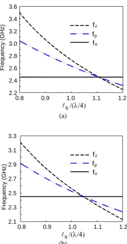
Fig. 3. Dependence of the transmission zero fz and pole
frequencies, fo and fp, on normalized stub length. (a) UIR circuit.
(b) SIR circuit in Fig.1 and Fig.2.
Coupling strcuture A
Coupling structure B
In Out
Out In
Fig. 4. Two coupling structures for tapped λ/4 UIRs.
II. PROPERTIES OF TAPPED λ/4 UIRS AND SIRS
The SIR shown in Fig.1 will have two resonant frequencies due to the open stub. The length and the impedance ratios of the low impedance to the high impedance sections of the SIR are 2 and 0.3, respectively,
so that the spurious resonance can be pushed more than three times the fundamental frequency [5]. The IE3D software [9] is used to do the simulation. In Fig.1, the structure is fed with microstrips through small gaps at both ends, and both conductor and dielectric are assumed loss free to have peak frequencies with a good accuracy. Note that when the impedance ratio is unity, the resonator becomes a UIR. Both the SIR and UIR without stub are designed to have a resonant frequency at fo = 2.45 GHz.
Fig.2 plots the |S21| response of the circuit in Fig.1. A
transmission zero fz and two transmission poles fo and fp
can be observed. Before the circuit design, it is important to investigate the dependence of these three frequencies on the dimension of the stub. Fig.3(a) and Fig.3(b) plot the variations of fz, fo and fp against the stub length for the
UIR and SIR circuits, respectively. The stub length is normalized with respect to the corresponding quarter-wave resonator at 2.45 GHz. Fig.3 indicates some important properties of fz, fo and fp as follows. The
fundamental frequency fo is fixed at 2.45 GHz and it is
independent of the stub length. The transmission zero fz
can be located either on lower or upper side of the passband, and fp always locates between fo than fz. It is
interesting to note that when ls/(λ/4) = 1.10 and 1.045 for
the UIR and SIR cases, respectively; the three curves intersect at 2.45GHz, the design frequency.
III. THE FILTER DESIGN
The design method for the investigated filter is as follows. For a bandpass filter with sharp transitions at passband edges, two transmission zeros are required. The intuitive way is to cascade two two-pole filters in Fig.1. In the design, first locate fz on both sides of the passband,
tune the resonator size if necessary, and then adjust the couplings in the structure. Since the transmission zeros have been determined by the stub length, their frequencies are unchanged during the cascading of the two stages. This can greatly save time in synthesizing the filter response.
IV. UIR FILTER RESPONSES
Consider a two-stage UIR filter with coupling structure A in Fig.4. According to our experience, the contribution from fp to the coupling coefficients in the filter is
negligible. Thus, the synthesis of the passband response can be approximated by three coefficients K01, K12 and K23
determined by fo of the main resonators. For a Butterworth
response with a fractional bandwidth ∆ = 10%, K01 = K23
= 0.30 and K12 = 0.11. If a coupling angle of 60o is used,
a substrate with εr = 10.2 and thickness 1.27 mm. The
sizes of the quarter-wave resonators have to be slightly trimmed. It is found that the resonator tapped with longer stub has to be cut down by 6%, and the other one has to be increased by 4%. Fig.5(a) shows the simulation and measured results for the filter. The frequencies of the zeros are chosen at 2.3 and 2.6 GHz. The measured insertion loss at the center frequency is 1.5dB.
The filter can also be implemented by structure B in Fig.4. It is found that the size of either resonator has not to be trimmed for compensating the change of phase constants from single microstrip to coupled three-lines for the input and output couplings. The reason why this filter structure possesses the two transmission zeros created by the stubs can be explained as follows. It can be seen that at either one zero frequency fz, the center of the
corresponding resonator is grounded, and the distance from the center to the open end of the resonator corresponds to a resonant frequency other than fz. Thus, at
fz, the input signal can neither be coupled into the main
resonators, nor pass through the filter.
Frequency(GHz) 1 -70 Simulation Measured -60 -50 -40 -30 -20 -10 0 2 3 4 5 |S |, |S | (dB) 21 11 (a) Frequency (GHz) -35 1 2 Simulation Measured 3 4 5 -30 -25 -20 -15 -10 -5 0 |S |, |S | ( d B) 11 21 (b)
Fig. 5. Simulation and measured responses of four-pole filters with tapped UIRs. Responses for (a) coupling structure A and (b) coupling structure B in Fig.4.
Coupling strcuture A Coupling structure B Out In In Out
Fig. 6. Two coupling structures for tapped λ/4 SIRs.
-50 2.0 Frequency(GHz) Measured Simulation -40 -30 -20 -10 0 2.2 2.4 2.6 2.8 3.0 |S |, |S | (d B) 11 2 1 (a) 1 -80 Frequency (GHz) Measured Simulation -70 -60 -50 -40 -30 -20 -10 0 10 2 3 4 5 6 7 8 9 10 11 12 11 |S |, |S | (dB) 21 (b)
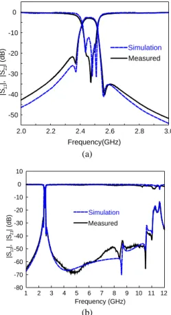
Fig. 7. Simulation and measured responses of four-pole filters with tapped SIRs with coupling structure A in Fig.6. (a) Detailed responses. (b) Responses in a broader band.
V. SIR FILTER RESPONSES
The filters in Fig.5 present a spurious response at twice the fundamental frequency. It degrades the attenuation level of the filter in the upper rejection band. Therefore, we design the bandpass filters with SIRs. There are also at
least two possible coupling structures for cascading the two SIR filter stages, as shown in Fig.6. In coupling structure A, the coupling between the tapped resonators is performed by the central parallel-coupled lines. Fig.7(a) shows the simulation and measured responses from 2 to 3 GHz, and Fig.7(b) shows those from 1 to 12 GHz. The insertion loss at the center passband is 2.6dB. The rejection level at twice the design frequency (4.9GHz) is close to 70dB. The filter has an attenuation level better than 40dB before the unwanted response goes up at 10.5 GHz. The extra transmission zero at 8.5 GHz is produced by the input and output coupled stages, and that at 10.5 GHz is the second attenuation pole of the open stepped impedance stub.
Fig.8(a) plots the simulation and measured responses of the SIR filter fed with a three-line structure from 2 to 3 GHz and Fig.8(b) shows those from 1 to 10 GHz. The passband insertion loss is 1.7dB at the design frequency. The spurious response goes up at 8GHz, and before this frequency the attenuation level is about 30dB.
-25 2.0 Frequency(GHz) Measured Simulation -20 -15 -10 -5 0 2.2 2.4 2.6 2.8 3.0 |S |, |S | ( d B ) 11 21 (a) -45 1 Frequency (GHz) Simulation Measured -40 -35 -30 -25 -20 -15 -10 -5 0 2 3 4 5 6 7 8 9 10 |S | , |S | (dB) 11 21 (b)
Fig. 8. Simulation and measured responses of four-pole filters with tapped SIRs with coupling structure B in Fig.6. (a) Detailed responses. (b) Responses in a broader band.
VI. CONCLUSION
A simple design for bandpass filters with a sharp transition is presented. The building blocks of the filters are quarter wavelength uniform impedance resonators (UIRs) and stepped impedance resonators (SIRs). Both direct coupling and a three-line microstrip structure are used to realize the cascade of two filter stages, which have a transmission zero on the lower and upper sides of the passband. The UIR design presents a good |S11| responses
as well as good insertion loss in the passband, while the SIR design possesses a wide upper rejection band with a good attenuation level in the rejection band. All the filters shown here have a sharp transition band.
ACKNOWLEDGEMENT
This work was supported in part by the National Science Council, TAIWAN, under Grants NSC 92–2213–E–009–079, and in part by the joint program of the Ministry of Education and the National Science Council under Contract: 89–E–F–A06–2–4.
REFERENCES
[1] J.-S. Hong and M. J. Lancaster, “Couplings of microstrip square open-loop resonators for cross-coupled planar microwave filters,” IEEE Trans. Microwave Theory &
Tech., vol. 44, no. 11, pp. 2099–2109, Nov. 1996.
[2] J.-T. Kuo, M.-J. Maa, and P.-H. Lu, “A microstrip elliptic function filter with compact miniaturized hairpin resonators,” IEEE Microwave and Guided Wave Letters, vol. 10, no. 3, pp. 94–95, Mar. 2000.
[3] C.-C. Yu and K. Chang, “Novel compact elliptic-function narrow-band bandpass filters using microstrip open-loop resonators with coupled and crossing lines,” IEEE Trans.
Microwave Theory & Tech., vol. 46, no. 7, pp. 952–958,
July 1998.
[4] K. Wada and I. Awai, " Heuristic models of half-wavelength resonator bandpass filter with attenuation poles," IEE Electronics Letters, vol. 35, no. 5, pp. 401–402, Mar. 1999.
[5] J.-T. Kuo and E. Shih, “Microstrip stepped impedance resonator bandpass filter with an extended optimal rejection bandwidth,” IEEE Trans. Microwave Theory Tech., vol. 51, no. 5, pp. 1554-1559, May 2003.
[6] S.-Y. Lee and C.-M. Tsai, “New cross-coupled filter design using improved hairpin resonators,” IEEE Trans.
Microwave Theory and Tech., vol.48, no.12, pp. 2482–2490,
Dec. 2000.
[7] J.-R Lee, J.-H. Cho and S.W. Yun, “New compact bandpass filter using microstrip λ/4 resonators with open stub inverter,” IEEE Microwave and Guided Wave Letters, vol. 10, no. 12, pp. 526–527, Dec. 2000.
[8] J.-T. Kuo and E. Shih, “Wideband bandpass filter design with three-line microstrip structures,” 2001 IEEE MTT-S Int.
Microwave Symp. Dig., pp.1593-1596, May 2001.
行政院國家科學委員會補助國內專家學者出席國際學術會議報告
93 年 6 月 16 日
報 告 人 姓 名 郭仁財 服 務 機 構 及 職 稱 交通大學電信系 教授 時 間 會議 地 點 93 年 6 月 6 日 至 6 月 11 日 美國德州 Fort Worth 市 本 會 核 定 補 助 文 號 國科會計畫 NSC 92-2213-E-009-079 會 議 名 稱 (中文)2004 國際微波工程與學術會議(英文)2004 International Microwave Symposium
發表論文題目 (中文)類橢圓函數響應之二階 UIR 與 SIR 濾波器設計 (NSC 92-2213-E-009-079) (英文)
Design of Two-Stage UIR and SIR Bandpass Filters with an Elliptic Function-Like Response
報告內容應包括下列各項: 一、參加會議經過
今年的國際微波工程與學術會議於 6 月 6 日至 6 月 11 日在美國德州 Fort Worth 市(達拉斯 Dallas 附近) 舉行。整個會議的議程包括(1)三十五場的密集課程(Workshop),討論電磁微波的教育、WLAN solution、4G 接 收機設計、濾波器設計技術、軟體無線電(software define radio)、無線電路與系統之測試、高功率射頻積體電路封 裝技術、微波接收機中的數位信號處理技術、矽晶高頻電子電路之雜訊分析、MEMS 技術與微波應用、靜電防護技 術等等,都是目前微波與無線電工業及教育界熱門的話題,(2)RF積體電路(RFIC)論文研討,以及(3)微波理 論與技術(MTT)國際學術論文研討(IMS,international microwave symposium)。
從 6 月 8 日到 10 日的個別論文研討中,由 970 篇投稿中選出的 489 篇論文,有 50% 投稿論文被拒絕,可 見大會審稿相當相當嚴格;發表的論文中,有 57% 來自非北美地區,表示在整個世界微波的研究,有逐漸成長的趨 勢。 筆者於 6、7 日到會場旁聽 RFIC 密集課程,以瞭解微波技術在目前 RFIC 發展的趨勢、遭遇的瓶頸、及各種 解決方案,吸收各演講者在其領域的成就,獲益相當豐富。8 至 10 日是 IMS 論文研討,筆者大部分時間在趕場, 如先原先預期,大會所選出的論文品質都相當優良,每一位演講者也都能盡心盡力,做出最好的表現,令人覺得所參 加的是品質很高的學術研討會。值得一提的是,筆者所參加 session 的主席,在開會兩週前就送 e-mail 通知所有演 講者,必須在開會前一週以 e-mail 寄演講的投影片給他看過,以維持演講的品質,屆時只要按 Pg Dn 就可以演講了, 不需再用磁片、光碟,也免除系統相容的問題。這是很好的作法,可供國內辦研討會的參考。筆者的論文在 10 日的 下午做論文的口頭報告,以「類橢圓函數響應之二階 UIR 與 SIR 濾波器設計」為題演講。 二、與會心得 今年 MTT-S 的論文有個很大趨勢的改變,傳統 MTT 論文像是波導管濾波器、場論分析、數值計算、平面混成 積體電路(hybrid MIC)等等的論文篇數,已經大幅縮減(約 20% - 30% 左右),取而代之的是一些 RFIC 的新技 術,例如 SiGe、MEMS、及高頻 IC 的包裝技術。其中高頻 IC 的包裝技術,應該是今年新增的主題,很可能是因 為封裝測試的技術已經面臨瓶頸,在數年內就無法滿足 IC 工作頻率的一再提高,這一點相當值得國內產業注意。另 外,筆者個人相當感興趣的研究主題之一是「電磁數值方法」,仔細觀察幾年的 MTT-S 下來發現,一些傳統解析式 分析與計算,可謂已經銷聲匿跡,完全看不到蹤影,倒是 FDTD 與 FEM 依舊存活的很好,這是很有趣的現象。因 為今天電腦速度已經超過了 2GHz,商業軟體也大行其道,研究生的好逸惡勞,唯市場需求才肯學,對於基礎背景的 建立興趣缺缺,導致國內學者仍舊願意研究電磁數值方法者,已經相當少見。FDTD 與 FEM 在 MTT-S 依然可持續 不衰的原因,在於這兩種方法本身具有相當的靈活度,適合於各式各樣的電磁與波導問題,不受結構複雜度限制。可 以預見的是,在未來數年內,這兩種方法在 MTT-S 中仍舊會佔有相當的地位。 另外筆者發表論文屬於平面濾波器電路設計,其設計規格也逐年提高,尤其近兩年,每篇論文的難度增加許多,相當 不容易。接下來的一、二年,要研究什麼、要有如何程度的成果,確實也令筆者感覺,需要花很多時間思量與評估, 以期明年能夠再一次有良好的研發結果。 三、考察參觀活動(無是項活動者省略) 四、建議 能夠參與這種國際大型且優良的研討會,確實有備受尊榮的感覺,眼看著論文的品質一年一年的提升,這可說是 藉由國際的競爭與研討會的腦力激盪的情況下,所有人卯足全力求表現與肯定,無形中形成一股推動整個微波與無線 電通訊工業的強大力量。因此,如果國內微波界能夠每年在此研討會有個廿 – 卅篇論文,台灣在這方面的競爭力將 大幅前進,但是要有足夠的競爭力,確實應該要有充分的支持與鼓勵。 五、攜回資料名稱及內容 攜回資料有研討會論文集光碟一片。 六、其他