國 立 交 通 大 學
電子工程學系
電子工程研究所
碩 士 論 文
動態可調程序混合式自動重傳
控制機制
Dynamic Multi-processes HARQ
Transmission Control
研究生 : 李庭軒
指導教授: 黃經堯 教授
動態可調程序混合式自動重傳
控制機制
Dynamic Multi-processes HARQ
Transmission Control
研 究 生: 李庭軒 Student: Ting-Hsuan Li
指導教授: 黃經堯 Advisor: Ching-Yao Huang
國 立 交 通 大 學
電子工程學系
電子研究所
碩 士 論 文
A ThesisSubmitted to Department of Electronics Engineering & Institute of Electronics College of Electrical and Computer Engineering
National Chiao Tung University in partial Fulfillment of the Requirements
for the Degree of Master of Science
in
Electronics Engineering January 2012
Hsinchu, Taiwan, Republic of China
動態可調程序混合式自動重傳
控制機制
研 究 生: 李庭軒 指導教授: 黃經堯 教授
國立交通大學電子工程學系電子研究所
中 文 摘 要
隨著行動通訊的發展,語音傳輸不再是手持裝置唯一的用途。資訊服務成為無線傳 輸的要角,各式各樣雲端服務推陳出新,加上手持裝置的作業系統同時多工處理,不同 的資訊交換在各自的應用軟體背景傳輸,舉凡載入網頁時又在下載APP,瀏覽的地圖的 同時還有免費訊息通訊軟體使用中,亦或是網路連線遊戲都已經在手持式裝置上推出。 此時單位時間的有效傳輸量就有更大的需求。現代無線通訊系統正在從3G語音導向的架 構到4G以封包導向演進,因為單位時間的有效傳輸量越來越顯的重要,我們提出新的構 想來降低在LTE/LTE-A (FDD) 中順序性傳輸對有效傳輸量的衝擊。Abstract
With the rapid development of wireless communication technology, cell phones are able to provide more and more services besides just making phone calls. More and more new applications come into life. For example, mobile on-line games, which may need low latency, and web browsing as well. Because users often need these services to run at the same time, multi-task technology may be needed to serve the demands, because it can provide high data throughput. In order to solve the above problems, we propose a new method to decrease the impact “in-sequence delivery” in LTE-A FDD system.
誌 謝
首先得感謝我的指導教授 黃經堯教授這兩年不僅是研究上的教導,使得我的研究所 生涯可以順利度過,也讓不是本科系出身的我對無線通訊領域有更深入了解。更感謝老 師在為人處事上的教導,這些人生經驗的學習是可遇不可求的。感謝口試委員 張錫嘉 教授和 趙禧綠教授給予的寶貴意見,在碩士的最後階段點出了盲點與缺失。另外感謝 周建銘學長當初在論文上的寶貴建議,讓最後論文的雛形得以草擬出來。感謝曾理銓學 長在我碩一修課上的幫助,讓我的研究所生涯起頭平順了許多。 最後,我更要感謝一直關心我、鼓勵我的家人以及朋友,如果沒有這些支持我無法順 利度過研究所生涯,讓我可以走過這段特別的人生道路。謝謝郭彥甫學長分享的一切, 不管是課業或是經驗的部分都是非常寶貴的。特別感謝林珈宇小姐,把一位女人最珍貴 的歲月都花在我身上。也在文章的最後感謝我的父母 李振煜先生和 陳淑真女士,支持 我無後顧之憂得完成求學階段,並讓我在一個幸福家庭長大。僅獻上此論文代表我對所 有人的敬意。Contents
Abstract iii
Contents v
Figure Captions vii
Table Captions x
1 Introduction 1
2 The overview of LTE system 2
2.1 Evolution of LTE………..2
2.1.1 Standardization of LTE………..3
2.1.2 Multicarrier Technology………5
2.1.3 Multiple Antennas……….6
2.2 LTE Network Architecture………7
2.2.1 The Core Network……….8
2.2.2 The Access Network………..9
2.3 LTE Protocol Architecture………10
2.3.1 User Plane………..10
2.3.2 Control Plane……….10
2.4 LTE User Plane Stack Introduction………..11
2.4.1 Packet Data Convergence Protocol (PDCP) Layer………12
2.4.2 Radio Link Control (RLC) Layer………14
2.4.3 Medium Access Control (MAC) Layer………..19
3 HARQ Introduction 23
3.1 Retransmission Mechanism………23
4 Dynamic Multi-processes HARQ Transmission Control 30
4.1 HARQ time budget………30
4.2 The performance analysis………36
5 Conclusion 45
Figure Captions
Fig 2.1 The standardization phases and iterativeFig 2.2 Releases of 3GPP specifications for LTE.
Fig 2.3 3GPP time schedule for LTE-Advanced in relation to ITU time-schedule on IMT-Advanced.
Fig 2.4 Frequency-domain view of the LTE multiple-access technologies. Fig 2.5 Three fundamental benefits of multiple antennas
Fig 2.6 The EPS network elements.
Fig 2.7 Overview of the EPC LTE architecture. Fig 2.8 Functional split between E-UTRAN and EPC. Fig 2.9 Overall E-UTRAN architecture.
Fig 2.10 The E-UTRAN user plane protocol stack. Fig 2.11 Control-plane protocol stack.
Fig 2.12 Overview of user-plane architecture. Fig 2.13 Overview of user-plane PDCP. Fig 2.14 Overview of control-plane PDCP Fig 2.15 The Transparent Mode RLC entity Fig 2.16 The Unacknowledged Mode RLC entity Fig 2.17 RLC PDU containing
Fig 2.18 Example of PDU loss detection with HARQ reordering Fig 2.19 Sequence number added in Tx
Fig 2.20 The receiving UM RLC entity checks the sequence number Fig 2.21 The Acknowledged Mode RLC entity.
Fig 2.23 Conceptual overview of the UE-side MAC architecture. Fig 2.24 The function blocks of MAC
Fig 2.25 Multiple parallel HARQ processes.
Fig 2.26 Timing diagram of the downlink HARQ (SAW) protocol Fig 2.27 Timing diagram of the uplink HARQ (SAW) protocol Fig 3.1 Illustration of data flow through L2 protocol stack
Fig 3.2 HARQ and ARQ retransmissions on MAC and RLC layer Fig 3.3 Rate matching and hybrid-ARQ functionality
Fig 3.4 The expression of soft combine Fig 3.5 The TCP throughput utilization
Fig 3.6 TCP Throughput Utilization with TCP E2E RTT and DL HARQ RTT Fig 4.1 LTE(FDD) HARQ transmission time budget
Fig 4.2 LTE network latency from Signals Research Group Fig 4.3 LTE network latency distribution
Fig 4.4 The expression of latency Fig 4.5 The influence of the MS moving
Fig 4.6 The benefit of doing retransmission quickly. Fig 4.7 The original MAC layer software architecture
Fig 4.8 The additional function blocks in the software platform Fig 4.9 The detail functions of each block
Fig 4.10 The threshold of incorrect values removing.
Fig 4.11 Using the end to end latency budget to approximate the HARQ transmission latency Fig 4.12 Different UL round trip latency with DL 8ms Utilization
Fig 4.13 The improvement of different UL round trip latency with DL 8ms Utilization Fig 4.14 Different UL round trip latency with DL 12ms Utilization
Fig 4.15 The improvement of different UL round trip latency with DL 12ms Utilization Fig 4.16 The Improvement of different UL round trip latency with DL 16ms utilization Fig 4.17 The maximum and minimum improvement. (a)10ms~200ms (b)10ms~100ms (c) 110ms~200ms
Fig 4.18 Average UL round trip latency with DL 8ms utilization.
Fig 4.19 The improvement of average UL round trip latency with DL 8ms utilization. Fig 4.20 Average UL round trip latency with DL 12ms utilization.
Fig 4.21 The improvement of average UL round trip latency with DL 12ms utilization. Fig 4.22 Average UL round trip latency with DL 16ms utilization.
Fig 4.23 The improvement of average UL round trip latency with DL 16ms utilization. Fig 4.24 The maximum and minimum improvement. (a)10ms~200ms (b)10ms~100ms (c) 110ms~200ms
Table Captions
Table 3.1 TCP RTT Increment with ARQ and HARQ OperationsChapter 1 Introduction
With the development of wireless communication, lots of industries are deeply influenced. And new technology also brings new applications. Although 4G systems bring high data rates, it is also more challenging to transmit data reliably.
In the last few decades, mobile communication devices are expensive. But with the development of wireless technology and semi-conductor manufacturing technology, these communication devices become cheaper and change our life.
The evolution of mobile communication devices can be categorized into four stages. We will give a brief introduction for them. The 1-G systems are analogy systems, and perform no more making phone calls. Then with the introduction of digital signal processing technique, cell phones become digital. Also, messaging service also come into life. In 3G system, besides voice and message services, multi-media are also introduced, and other none voice service else well. But date rates in 3G systems are not enough for those services. That`s why 4G systems are introduced. More details for 4G LTE system are given in the following sections.
In chapter 2, we give simple introductions for LTE system. In this thesis, we focus on the Radio Link Control (RLC) layer and Medium Access Control (MAC) layer.
In chapter 3, more detailed RLC layer and MAC layer block diagrams will be provided. We also will discuss the impact of “in-sequence delivery” in this chapter.
Chapter 2 The overview of LTE system
People like divide the mobile communication technologies into generations. TheLong-Term Evolution (LTE) is called “4G”.But strictly, Many People claim that LTE release 8 should be called “3.9G”. LTE-Advanced (LTE release 10) is the true “4G”. Labels are not the most important, people care the capabilities evolved. This chapter describes the
background of LTE system.
2.1 Evolution of LTE
The most deferent between “3G” and “4G” is that new kind services for mobile devices, enabled advanced technology available. The internet plays an important role in modern life, which has been widespread used. Move the internet-based services to the mobile devices that is the natural step. Although there are a few of services were already provided by “2.5G” systems, but it is not designed primarily for Internet Protocol (IP)-based. Unlike earlier mobile technology built for circuit switch services and are primary on voice. HSPA and LTE/LTE-A are designed for packet-switched primarily. The voice application still remain with Voice-over IP (VoIP).
The main service-related design parameters are:
Data rate
In the most of cases, a service can be provided or not decided by data rate. The higher data rates needed such for web browsing, file transfer and streaming (ex: YouTube). The peak data rates from Mbit/s for “3G” to Gbit/s for ”4G”.
Capacity
It is not just only end-user data rate important. In the operator’s opinion, total data rate can be provided on average are also considered. How a mobile system can provide total data rate for each base station site and per hertz of licensed spectrum, which called “spectral efficiency”.
Delay
Due to lots of new real time application came out, the issue of delay also become more important. The delay for a packet from the sever to the client is called latency.
The evolution of the technology to 4G is not just only depend on the three parameters mentioned. There are also other demands required. For example, more spectrum resources to expand systems and more challenge to combine alternative technologies to provide mobile services.
2.1.1 Standardization of LTE
It is not a one-time job to set a standard for mobile wireless communication. There are typically four phases illustrated in Fig 2.1[1]:
1.Requirements
Where it is decided what is to be achieved by the standard.
2.Architecture
Where the main building blocks and interfaces are decided.
3.Detailed specifications
Where every interface is specified in detail.
4.Testing and verification
Where the interface specifications are proven to work with real-life equipment.
Standardization often starts from the “requirement” phase, where the standards body decides what should be achieved.
In the “architecture” phase, the standards body have to decide the principles of meeting the requirements.
The next phase, the “detailed specification” phase starts. The details for each of the identified interfaces are specified.
Finally, “testing and verification” starts. During this phase, errors may still be found in the standard. There are still some chance to change decisions in the detailed standard.
Fig 2.3 3GPP time schedule for LTE-Advanced in relation to ITU time-schedule on IMT-Advanced.[1]
2.1.2 Multicarrier Technology
One of the most important feature in LTE is that multicarrier approach for multiple access[2]. Finally, people selected Orthogonal Frequency-Division Multiple Access (OFDMA) for the downlink, and Single-Carrier Frequency-Division Multiple (SC-FDMA) for the uplink[3]. With these schemes, the mobile system become more flexible in the frequency domain. As illustrated in Fig 2.4[4] :
In OFDMA, multiple users can share the subcarriers. The flexibility let people used in various ways:
Without changing the fundamental system parameters or equipment design, different spectrum bandwidths still can be used.
Different users can be allocated freely in transmission resources of variable bandwidth and scheduled freely in the frequency domain.
It is easy for cells in fractional frequency reusing and interference coordination.
2.1.3 Multiple Antennas
There are variety of features in multiple antenna technology. But not all of them are easy to implement in real mobile system. There are several ways to use multiple antenna
technology. There are three basic principles, as illustrated in Fig 2.5[4] : Diversity gain
Enhance the transmission against multipath fading by space-diversity with multiple antenna technology.
Array gain
Concentration of energy in one or more directions. Allows multiple users can be served at the same time.
Spatial multiplexing gain
A single user can use multiple spatial layers in transmission of multiple streams.
2.2 LTE Network Architecture
As just mentioned, LTE designed for packet-switch services[5]. In order to provide
directly Internet Protocol (IP), the connectivity between User Equipment (UE) and the Packet Data Network (PDN) should be seamless. There are two parts in LTE. The first radio access part named Evolved-UTRAN (E-UTRAN), it is accompanied by the other non-radio part named System Architecture Evolution (SAE) which includes the Evolved Packet Core (EPC) network. Both of these parts called the Evolved Packet System (EPS).
Fig 2.6 The EPS network elements.[4]
EPS helps the users to access the Internet. Also includes running services such as Voice over IP (VoIP).
2.2.1 The Core Network
The Core Network controls the UE and establishment of the bearers. The following nodes are the main logical nodes of the EPC :
Mobility Management Entity (MME).
The MME controls the signaling processes between the CN and the UE. The protocol between them named Non-Access Stratum (NAS) protocol.
PDN Gateway (P-GW).
The IP address allocation for the UE is the responsibility of The P-GW. Serving Gateway (S-GW).
All IP packets form the users are transferred through the S-GW.
2.2.2 The Access Network
The Access Network of LTE as illustrated in Fig 2.9[8]:
Fig 2.9 Overall E-UTRAN architecture.© 3GPP[8]
The protocols between the eNodeBs and the UE named the Access Stratum (AS). All of radio-related functions are responsibilities of E-UTRAN :
Radio Resource Management (RRM).
The functions related to the radio bearers. For example : radio mobility control, admission control, radio bearer control, scheduling and resource allocation to the UEs in uplink and downlink.
Header Compression. Security.
Connectivity to the EPC.
Unlike previous generation mobile wireless communication systems, LTE integrates the radio control functions into the eNodeB. It tight interaction between the different protocol layers of the radio access network. The important benefits are reducing latency and improving efficiency.
2.3 LTE Protocol Architecture
This is a simple protocol architecture introduction of E-UTRAN.
2.3.1 User Plane
The E-UTRAN user plane protocol stack is shown in Fig 2.10[4] of the gray part. There are three sub-layers in the plane. They are Packet Data Convergence Protocol(PDCP), Radio Link Control(RLC) and Medium Access Control(MAC). All of them are terminated in the eNodeB on the network side.
Fig 2.10 The E-UTRAN user plane protocol stack. Reproduced by permission of © 3GPP[4]
2.3.2 Control Plane
The control plane between the UE and MME as illustrated in Fig 2.11.[4] The sub-layers are almost as the same as sub-layers in the user plane. The only difference between them that there is no header compression in the control plane.
Fig 2.11 Control-plane protocol stack. Reproduced by permission of © 3GPP[4]
2.4 LTE User Plane Stack Introduction
The packet Data Convergence Protocol (PDCP) :The PDCP handles the Radio Resource Control (RRC) messages in the control plane and Internet packet in the user plane. The main functions in the PDCP are integrity and ciphering, header compression and reordering and retransmission during handover.
The Radio Link Control (RLC) :
Segmentation and reassembly of the upper layer packets in order to arrange their size is the main task in RLC layer. The RLC has to handles the ordering of the Hybrid Automatic Repeat request (HARQ) packets from the MAC layer. There also is Automatic Repeat request (ARQ) function in the RLC own layer for error free transmission.
The Medium Access Control (MAC) :
The MAC layer processes multiplextiong of data from different radio bearers. Achieving the Quality of Service (QoS) required is one of the MAC layer tasks. There is Hybrid Automatic Repeat request (HARQ) function in this layer, which provides a quick error recovering mechanism.
Fig 2.12 Overview of user-plane architecture[4]
When transmitting, each layer receive the packet form the upper layer called the Service Data Unit (SDU), and output the packet called Protocol Data Unit (PDU) to the lower layer.
2.4.1 Packet Data Convergence Protocol (PDCP) Layer
This layer provide the below functions:
Header compression and decompression (only in the user plane). Security :
Ciphering and deciphering.
Integrity protection and verification (only in the control plane). Handover
Promising in-sequence delivery at handover.
When the RLC layer in Acknowledge Mode (AM), the PDCP processes losslees handover.
Fig 2.13 Overview of user plane PDCP. Reproduced by permission of © 3GPP[4]
There are two different types of PDCP PDU in LTE : PDCP control PDUs and PDCP data PDUs. Both control plane and user plane exist PDCP data PDUs. The main information PDCP control PDUs carrying are feedback information for header compression and PDCP status reports. Because the status are using for handover, the PDCP control PDUs only exists in the user plane.
2.4.2 Radio Link Control (RLC) Layer
The RLC layer is in the middle of the PDCP layer and the MAC layer. The RLC has to resize the packets from the PDCP PDUs in order to match the size indicated by the MAC layer[9].
The other important task in the RLC layer is handling the out of sequence RLC PDUs due to HARQ operation in the MAC layer. Unlike some of other mobile communication systems , the reordering task belongs the MAC layer. The advantage of HARQ reordering in the RLC layer is reducing some overheads because of no additional Sequence Number (SN). Also it can save the reception buffer needed for HARQ reordering.
All the functions are performed by the RLC entity. There are three data transmission modes : Transparent Mode (TM), Unacknowledged Mode (UM), and Acknowledged Mode (AM). The following are the introduction for the three types of mode.
Transparent Mode (TM) RLC Entity
When the RLC turn to Transparent Mode (TM), there is no RLC overhead. The RLC SDUs are directly mapped to the RLC PDUs. The Transparent Mode (TM) is often used for transporting control messages.
Unacknowledged Mode (UM) RLC Entity
The Unacknowledged Mode (UM) is used for transmitting delay-sensitive and error-tolerant real time applications. For example, Voice over Internet Protocol (VoIP) and other delay-sensitive streaming services. The Multimedia Broadcast and Multicast Service (MBMS) also use the Unacknowledged Mode (UM).
Fig 2.16 The Unacknowledged Mode RLC entity.
The main tasks of the Unacknowledged Mode are as follows: Segmentation and concatenation
Because the transmission opportunity is decide by the Medium Access Control (MAC) layer. In order to operate the radio channel condition, the RLC PDU can be different. A single RLC PDU can contain RLC SDUs or segments of RLC SDUs as illustrated in Fig 2.17:
Fig 2.17 RLC PDU containing
After segmentation and/or concatenation, the packet will be put on the UM RLC header. The sequence number of RLC PDU and the size and boundary of each included RLC SDU or RLC segment also are described.
RLC PDUs reordering
RLC PDUs duplicate detection RLC SDUs reassembly
When the receiving UM RLC entity receives the RLC PDUs, it will check if they are out of sequence or not. Because of multiple parallel HARQ processes operation are used in the Medium Access Control (MAC) layer, out-of-sequence reception is hard to avoided. There is a buffer well prepared to store out of sequence.
The UM RLC entity also do the duplicate detection during the reordering process. This ensures that the upper layer will not receive the same RLC SDU twice.
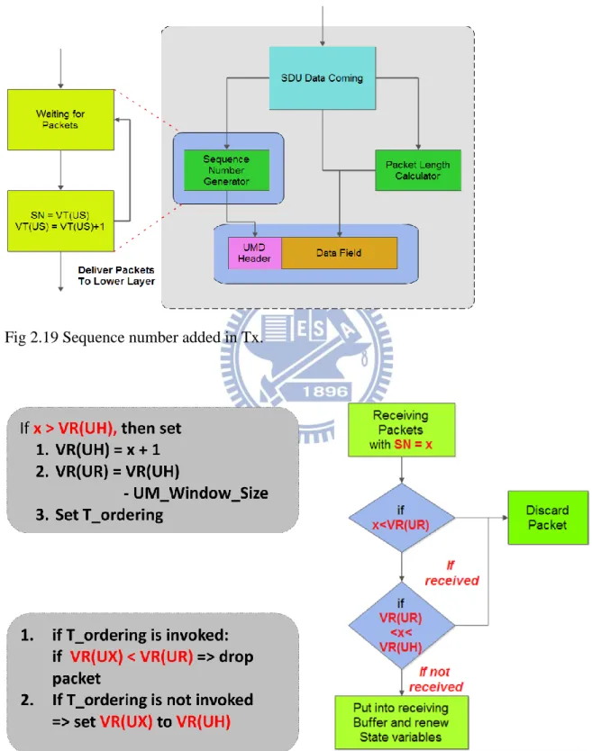
In order to avoid heavy reordering delays, a reordering timer is prepared in the receiving UM RLC entity to control the maximum time to wait for the reception. When a missing RLC PDU is detected , the receiving UM RLC entity will start the reordering time to wait for a while. The idea is as illustrated in the Fig 2.18[4]:
The following Fig 2.19 and Fig 2.20 do a simple illustration of RLC reordering. The UM transmitting RLC entity always puts on the sequence number. When a new RLC PDU comes ,the receiving UM RLC entity checks the sequence number.
Fig 2.19 Sequence number added in Tx.
Acknowledged Mode (AM) RLC Entity
The most different between the AM RLC entity and others is the retransmission function enable in the Acknowledged Mode (AM). An Automatic Repeat request (ARQ) operation is used for error free transmission. The Acknowledged Mode (AM) often provides error sensitive and delay tolerant non-real time application such as file exchanging, web browsing and messages.
Fig 2.21 The Acknowledged Mode RLC entity.
There are some additional functions in the AM RLC entity: Retransmission and re-segmentation of RLC data PDUs Polling, status reporting and prohibit
As mentioned, retransmission is the most feature in the Acknowledged Mode (AM). When transmitting AM RLC entity transmits the RLC data PDUs , it stores those PDUs in the retransmission buffer. In case of the channel condition variation told by the Medium Access Control (MAC) layer, the transmitting AM RLC entity can re-segment the original RLC data PDUs into smaller PDU segments. The following of the Fig 2.22[4] illustrated the AM RLC entity doing the re-segmentation of retransmission.
Fig 2.22 Example of RLC re-segmentation.[4]
2.4.3 Medium Access Control (MAC) Layer
The MAC layer performs multiplexing, de-multiplexing and HARQ. The MAC PDUs also called transport blocks[10].
MAC Architecture
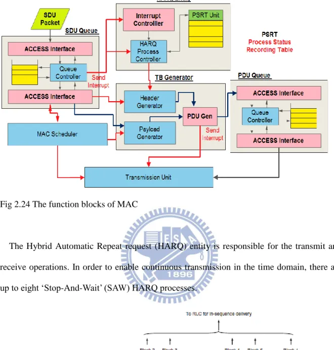
The Fig 2.23[4] shows the overview of MAC architecture.
Fig 2.24 The function blocks of MAC
The Hybrid Automatic Repeat request (HARQ) entity is responsible for the transmit and receive operations. In order to enable continuous transmission in the time domain, there are up to eight ‘Stop-And-Wait’ (SAW) HARQ processes.
Fig 2.25 Multiple parallel HARQ processes.[1]
The ‘Stop-And-Wait’ ARQ operation means after a process transmit a transport block, the process will not send the next transport block until the receiver ACK/NACK back. Each HARQ process is responsible for a separate buffer.
There are different kinds of HARQ schemes, synchronous and asynchronous with retransmission in each case being non-adaptive or adaptive.
In the synchronous HARQ scheme, the retransmission occurring time be predefined in each process. It can save some signal information overhead. In the contrast of synchronous HARQ, the retransmission occurring time can occur at any time in the asynchronous HARQ. Although it will increase the signal overhead, the flexibility is better than the synchronous HARQ.
In LTE system, there two kind of HARQ types in uplink and downlink[11]. Asynchronous adaptive HARQ is used for downlink. In uplink, Synchronous HARQ is used. The retransmission may be adaptive or non-adaptive, depending on whether the new signaling is coming.
Chapter 3 HARQ Introduction
As like other wireless communication, the transmission errors still occur often in LTE. The retransmission handling still needed.
3.1 Retransmission Mechanism
In order to handle the bit errors, the physical layer add the 24-bit CRC checksum in the transport block. As illustrate in Fig. 3.1[6]:
Fig 3.1 Illustration of data flow through L2 protocol stack.[6]
The TCP/IP protocols are working in low packet-loss situation. The TCP-based file downloads need error rates about 10-5 to 10-6. So we need the HARQ mechanism in the MAC
that is responsible of correcting the majority of all transmission errors. In order to let HARQ do the fast error recover and consume few radio resources, it uses single-bit HARQ feedback acknowledgement/ negative acknowledgment (ACK/NACK). Although the single-bit HARQ feedback reduce the radio resource consume, there exist the probability for misunderstanding a negative acknowledgment as a positive acknowledgment. The situation will create additional residual errors, is in the order of 10-4 to 10-3.
Because the error cases just mentioned, there are highly reliable window-based ARQ protocol in the RLC layer as illustrated in Fig. 3.2[6]:
Fig 3.2 HARQ and ARQ retransmissions on MAC and RLC layer.[6]
The HARQ receiver delivers the RLC PDUs (Protocol Data Units) to the corresponding RLC entity when the CRC check is successful. If the RLC receiver detects the sequence number gap, it starts a reordering timer waiting the missing packet retransmission in the HARQ protocol. If the reordering timer expires, the acknowledged-mode (AM) RLC receiver sends the status message which point out the sequence numbers of missing RLC PDU(s). The
MAC layer. If today we want to do the real time application transmission, the RLC will be the acknowledged-mode (AM). It means the RLC ARQ operation will not work.
In order to do the trade-off between the performance and the radio resource. There are the two-layer ARQ design. The following sentences is the main idea:
The two-layer ARQ design achieves low latency and low overhead without sacrificing reliability. Most errors are captured and corrected by the lightweight HARQ protocol. Only residual HARQ errors are detected and resolved by the more expensive (in terms of latency and overhead) ARQ retransmissions.[6]
In order to decrease the packet error rate[12]. The transport block will be coded into four versions[13]. In LTE system, the HARQ maximum transmission times is four. As illustrated in Fig. 3.3[1]. The HARQ transmitter will transmit the different redundant version transport block when receiving the negative acknowledgment (NACK). The HARQ combine all the different version transport block that can increase the chance to decode[14].
Fig 3.4 The expression of soft combine.
3.2 The impact on “In-Sequence Delivery”[15]
In LTE link layer, the “In-sequence Delivery” will make some additional increment on TCP RTT(Round Trip Time). It is caused by that the HARQ (Hybrid Automatic Repeat request) in MAC layer or the ARQ (Automatic Repeat request) in RLC layer is working for error recovery. The “In-sequence delivery” in LTE link increase TCP RTT and decrease TCP throughput. If the RLC receiver detect the gap of sequence number in received RLC PDUs, the reordering timer will be started to waiting the HARQ retransmission. In order to know the impact of “In-sequence delivery”, we have the TCP throughput utilization equations[15]. There two parts of RTT (Round Trip Time), the first part exclude of the HARQ (Hybrid Automatic Repeat request) in MAC layer or the ARQ (Automatic Repeat request) in RLC layer execution time. The second part are the remainder.
(3.1)
(3.2)
Fig 3.5 The TCP throughput utilization[15].
From the LTE system design[6], the HARQ BLER should be on the order of 10-1. There
are also error probability of NACK-to-ACK on the order of 10-4 and RLC PDU loss
probability after the HARQ operation is about 10-3. From the performance simulation
design[15], assuming the HARQ error rate is on the order of 10-2,5*10-3,2*10-3,and 10-3,after
two ,three ,four, and five HARQ transmissions each. But from 3GPP information[16], the maximum HARQ transmission times is four. In this thesis , we assume the HARQ error rate is on the order of 10-2,5*10-3,2*10-3,after two ,three , and four HARQ transmissions each. If
the transport block has been received successfully with just one HARQ transmission, for example, i=1,j=0,dk is 0. If the transport block has been successfully received with not just on
time, for example , i=2,j=0, Pi,j = 10-1,maximum of N is 8 and dk is HARQ RTT in maximum
and 0 in minimum (In fact, the maximum dk is as the same as N. The reason is about the
frame structure ). The RTTinc is 3.6 [P2,0*8*9/2=3.6]. Fig 3.5 shows all the RTT increment,
these values are only including one-way delay and if UL and DL is considered, total RTT increment is more than two times of one-way delay[15](All the fifth HARQ transmission should be excluded). inc e e e e RTT RTT RTT 2 2
m j n i N k k j i inc p d RTT 0 1 0 ,Table 3.1 TCP RTT Increment with ARQ and HARQ Operations[15].
The following Fig 3.6 shows the TCP throughput utilization with TCP end-to-end RTT of from 10ms to 200ms and average DL HARQ RTT of 8ms,12ms and 16ms[15] (The simulation results from “TCP Performance Degradation of In-Sequence Delivery in LTE Link Laye.[15]”, the fifth HARQ transmissions increment still be calculated. In next chapter, performance analysis will excluded all of the fifth HARQ transmissions).
Chapter 4 Dynamic Multi-processes HARQ Transmission Control
As we just mentioned, if ARQ and HARQ mechanisms perform too frequently, the impact of “In-sequence delivery in LTE link layer” is increased, then the TCP throughput is decreased[15]. In order to decrease the impact of “In-sequence delivery” under the same error rate, we propose a new mechanism called “Dynamic multi-processes HARQ transmission control”. In our method, we can retain the in-sequence delivery mechanism, while in the same time, we can decrease its impact.4.1 HARQ time budget
The budget of time resource is shown in Fig 4.1[17]. From Signals Research Group, LTE network latency is not always fixed[18]. According to other experiments, if we ignore the HARQ retransmissions, we can approximate the network latency with normal distribution[19]. In that experiment, they measure the network latency by sending data between two computers in LTE network.
Fig 4.2 LTE network latency from Signals Research Group[18].
Therefore, we expect the HARQ Round Trip Time (RTT) to be varied in real cases. We decompose the RTT into two parts, transmission delay and propagation delay separately. Firstly, we estimate the propagation delay. According to 3GPP, the longest distance from BS to MS is no longer than 100km, so the propagation delay should be less than 1 ms.
(4.1)
(4.2)
Fig 4.4 The expression of latency.
Here we consider that when the MS is moving. We consider the effect of mobility on propagation delay and hardware processing time, denoted 2*x(t)/c and H(t) respectively. We can see from (4.4) that the propagation delay does not change too much, even in the worst case that we are on the Taiwan High Speed Rail with velocity of 300Km/hr moving towards BS, as illustrated in Fig 4.5. From the result, we neglect the effect of MS mobility on latency compared to propagation delay.
(4.3) (4.4) p total x t H t Latency c t H t Latency ( ) ( )2 ( ) ( ) dt t dx c dt t dH dt t Latency d( total( )) ( ) 2 ( ) m ms m 0833 . 0 1000 3600 1000 300 ms ms m m 7 5 2.7 10 ) / ( 10 3 0833 . 0
Fig 4.5 The influence of the MS moving. © Taiwan High Speed Rail
In LTE, when performing HARQ transmission, each process has its own transmission buffer. When retransmission is needed, the process has to wait for 8ms. But from “TCP Performance Degradation of In-Sequence Delivery in LTE Link Layer.[15]”, we expect the retransmission to happen as soon as possible, and then the TCP throughput utilization can be improved.
Fig 4.6 The benefit of doing retransmission quickly.
In our project, we already have the MAC layer software ,which was designed based on LTE system MAC layer architecture. As illustrated in Fig 4.7. The HARQ entity get the
SDUs from the queue and control the transmission functionality. In order to realize my idea, I have to add three more functions. A latency generator and the latency measurement block and the thread calculator. Fig 4.8 shows the additional blocks.
Fig 4.7 The original MAC layer software architecture.
Fig 4.9 express the control flow. The latency generator give a random latency value. In order to handle the incorrect values. The latency measurement block not only collects the latency value but also calculates the standard variance and average. Finally the thread calculator find the appropriate thread value.
Fig 4.9 The detail functions of each block.
As just mentioned, the latency measurement block often calculates the standard variance and average. Sometimes we measured some incorrect values which we want to remove. Maybe it caused by multi-path transmission. When lots of latency we get. Calculate the standard variance and the average. Finally remove value over the threshold . We choose the threshold as illustrated in Fig 4.10.
Because the we have not found the method to measure the HARQ latency. We found the network latency information and use this end to end latency budget[20] to approximate the HARQ transmission latency (Fig 4.11).
Fig 4.11 Using the end to end latency budget[20] to approximate the HARQ transmission latency.
4.2 The performance analysis
Finally, we use the throughput utilization equation from “TCP Performance Degradation of In-Sequence Delivery in LTE Link Layer[15].” to analysis the performance improvement. At first, we show UL HARQ round trip latency of 5ms,6ms,7ms,8ms throughput utilization and the improvement with TCP end-to-end RTT of from 10ms to 200ms the and average DL HARQ RTT of 8ms,12ms and 16ms.
Fig 4.12 Different UL round trip latency with DL 8ms utilization.
Fig 4.13 The improvement of different UL round trip latency with DL 8ms utilization.
0
0.2
0.4
0.6
0.8
1
10 30 50 70 90 110 130 150 170 190
5ms
6ms
7ms
8ms
0
5
10
15
20
25
10 30 50 70 90 110 130 150 170 190
5ms(%)
6ms(%)
7ms(%)
Fig 4.14 Different UL round trip latency with DL 12ms utilization.
Fig 4.15 The improvement of different UL round trip latency with DL 12ms utilization.
0
0.2
0.4
0.6
0.8
1
10 30 50 70 90 110 130 150 170 190
5ms
6ms
7ms
8ms
0
5
10
15
20
25
10 30 50 70 90 110 130 150 170 190
5ms(%)
6ms(%)
7ms(%)
Fig 4.16 Different UL round trip latency with DL 16ms utilization.
Fig 4.16 The Improvement of different UL round trip latency with DL 16ms utilization.
There are many curves. Therefore, we arrange the improvement data of these cases. Fig 4.17 shows the maximum and minimum utilization improvement with TCP end-to-end RTT of from 10ms to 200ms. We also separate the two half of TCP RTT, it seems the improvement is much better when the TCP RTT below 100ms.
0
0.2
0.4
0.6
0.8
1
10 30 50 70 90 110 130 150 170 190
5ms
6ms
7ms
8ms
0
5
10
15
20
25
10 30 50 70 90 110 130 150 170 190
5ms(%)
6ms(%)
7ms(%)
Fig 4.17 The maximum and minimum improvement. (a)10ms~200ms (b)10ms~100ms (c) 110ms~200ms
Finally, we calculate the HARQ round trip latency for 1000 times ( 521 times of 6ms case and 479 times of 7ms case). We analysis the average performance improvement by the TCP throughput utilization[15].
Fig 4.18 Average UL round trip latency with DL 8ms utilization.
0
0.1
0.2
0.3
0.4
0.5
0.6
0.7
0.8
0.9
1
10 30 50 70 90 110 130 150 170 190
Average
8ms
Fig 4.19 The improvement of average UL round trip latency with DL 8ms utilization.
Fig 4.20 Average UL round trip latency with DL 12ms utilization.
0
2
4
6
8
10
12
10 30 50 70 90 110 130 150 170 190
gain
0
0.1
0.2
0.3
0.4
0.5
0.6
0.7
0.8
0.9
1
10 30 50 70 90 110 130 150 170 190
Average
8ms
Fig 4.21 The improvement of average UL round trip latency with DL 12ms utilization.
Fig 4.22 Average UL round trip latency with DL 16ms utilization.
0
2
4
6
8
10
12
10 30 50 70 90 110 130 150 170 190
gain
0
0.1
0.2
0.3
0.4
0.5
0.6
0.7
0.8
0.9
1
10 30 50 70 90 110 130 150 170 190
Average
8ms
Fig 4.23 The improvement of average UL round trip latency with DL 16ms utilization.
Fig 4.24 The maximum and minimum improvement. (a)10ms~200ms (b)10ms~100ms (c) 110ms~200ms
According to the other experiment result [19].They used ping command to send and receive data packets, the lengths of data packets means the size of data packet which are attached after ICMP headers. Ping command not only transmits those ICMP data packets, but also measures and reports the round-trip time (RTT). The mean value TCP RTT in LTE link layer often below 40ms. Although there is a limitation with TCP throughput utilization improvement when TCP RTT exceeds 100ms. From the experiment result[19]. It seems like that the “Dynamic multi-processes HARQ transmission control” still can provide a new
0
1
2
3
4
5
6
7
10 30 50 70 90 110 130 150 170 190
gain
Chapter 5 Conclusion
In this thesis, we propose a new method to decrease the impact on “in-sequence delivery” in LTE link. When ARQ and HARQ mechanism in LTE is working for the error recovery, TCP RTT is also increased, and hence the throughput utilization is decreased. With “Dynamic Multi-processes HARQ Transmission Control”, total throughput utilization in our method can be improved up to 11.4%. The utilization improvement decrease with the end to end RTT. The improvement of the worst case is only about 4%. But from the last experiment just mentioned. In typically application, TCP RTT is usually lees than 100ms. In that situation, our approach can provide good improvement.
Reference
1. Erik Dahlman, S.P., Johan Sköld, 4G LTE/LTE-Advanced for Mobile Broadband.
2011.
2. Anritsu, LTE Resource Guide. 2009.
3. Zyren, J., Overview of the 3GPP Long Term Evolution Physical Layer. 2007.
4. Stefania Sesia, I.T., Matthew Baker, LTE-The UMTS Long Term Evolution From
Theory to Practice. 2009.
5. Semiconductor, F., Long Term Evolution Protocol Overview.
6. Anna Larmo, M.L., Michael Meyer, Ghyslain Pelletier, Johan Torsner, and a.H.
Wiemann, The LTE Link-Layer Design. IEEE Communications Magazine, 2009. 7. 36.300, G.T., 3rd Generation Partnership Project; Technical Specification Group
Radio Access Network; Evolved Universal Terrestrial Radio Access (E-UTRA) and Evolved Universal Terrestrial Radio Access Network (E-UTRAN); Overall description;Stage 2 (Release 8). 2008.
8. 3GPP, UTRA-UTRAN Long Term Evolution (LTE) and 3GPP System Architecture
Evolution (SAE).
9. EventHelix.com, 3GPP LTE Radio Link Control (RLC) Sub Layer. 2009.
10. EventHelix.com, 3GPP LTE Channels and MAC Layer. 2009.
11. Schwarz, R., UMTS Long Term Evolution (LTE) Technology Introduction.
12. M. Wissem El Bahri, H.B., Mohamed Siala, Throughput evaluation of HARQ
Schemes with Packet and Code Combining over multipath fading channels for DS-SSS.
13. Ping-Chuan Kung, Y.T.S., Performance Analysis of Hybrid ARQ with Chase
Combining and Incremental Redundancy.
LTE H-ARQ. 2009.
15. Hyun-Seo Park, J.-Y.L.a.B.-C.K., TCP Performance Degradation of In-Sequence
Delivery in LTE Link Layer. International Journal of Advanced Science and Technology, 2011.
16. 37.901, G.T., User Equipment (UE) application layer data throughput performance. 2012. V11.2.0.
17. Per Beming, L.F., Göran Hall, Peter Malm, Thomas Noren, Magnus Olsson and
Göran Rune, LTE-SAE architecture and performance.
18. Group, S.R., The Real-World User Experience in an LTE and DC-HSDPA HSDPA N k
Network 2011.
19. XU, Y., Latency and Bandwidth Analysis of LTE for a Smart Grid. 2011.
20. M. Lazhar BELHOUCHET, M.H.E., Session 5 : LTE Technology Perofrmance
![Fig 2.3 3GPP time schedule for LTE-Advanced in relation to ITU time-schedule on IMT-Advanced.[1]](https://thumb-ap.123doks.com/thumbv2/9libinfo/8261665.172212/16.892.117.768.159.398/fig-gpp-time-schedule-advanced-relation-schedule-advanced.webp)
![Fig 2.9 Overall E-UTRAN architecture.© 3GPP[8]](https://thumb-ap.123doks.com/thumbv2/9libinfo/8261665.172212/20.892.111.662.239.511/fig-overall-e-utran-architecture-gpp.webp)
![Fig 2.10 The E-UTRAN user plane protocol stack. Reproduced by permission of © 3GPP[4]](https://thumb-ap.123doks.com/thumbv2/9libinfo/8261665.172212/21.892.122.736.460.752/fig-utran-user-plane-protocol-stack-reproduced-permission.webp)
![Fig 2.11 Control-plane protocol stack. Reproduced by permission of © 3GPP[4]](https://thumb-ap.123doks.com/thumbv2/9libinfo/8261665.172212/22.892.120.631.111.296/fig-control-plane-protocol-stack-reproduced-permission-gpp.webp)
![Fig 2.13 Overview of user plane PDCP. Reproduced by permission of © 3GPP[4]](https://thumb-ap.123doks.com/thumbv2/9libinfo/8261665.172212/24.892.115.579.108.490/fig-overview-user-plane-pdcp-reproduced-permission-gpp.webp)
![Fig 3.1 Illustration of data flow through L2 protocol stack.[6]](https://thumb-ap.123doks.com/thumbv2/9libinfo/8261665.172212/34.892.112.790.459.906/fig-illustration-data-flow-l-protocol-stack.webp)
![Fig 3.2 HARQ and ARQ retransmissions on MAC and RLC layer.[6]](https://thumb-ap.123doks.com/thumbv2/9libinfo/8261665.172212/35.892.115.785.486.825/fig-harq-arq-retransmissions-mac-rlc-layer.webp)
![Fig 3.3 Rate matching and hybrid-ARQ functionality[1]](https://thumb-ap.123doks.com/thumbv2/9libinfo/8261665.172212/36.892.116.805.476.962/fig-rate-matching-and-hybrid-arq-functionality.webp)
