國 立 交 通 大 學
電子工程學系 電子研究所碩士班
碩 士 論 文
多用戶雙向傳輸合作式中繼系統之中繼點選擇設計
Relay Selection in Multiuser Two-Way Cooperative
Relaying Systems
研 究 生: 廖怡茹
指導教授: 簡鳳村 博士
多用戶雙向傳輸合作式中繼系統之中繼點選擇設計
Relay Selection in Multiuser Two-Way Cooperative Relaying Systems
研 究 生: 廖怡茹 Student: Yi-Ju Liao
指導教授: 簡鳳村 博士 Advisor: Dr. Feng-Tsun Chien
國 立 交 通 大 學
電子工程學系 電子研究所碩士班
碩 士 論 文
A Thesis
Submitted to Department of Electronics Engineering & Institute of Electronics College of Electrical and Computer Engineering
National Chiao Tung University in Partial Fulfillment of the Requirements
for the Degree of Master of Science
in
Electronics Engineering January 2010
Hsinchu, Taiwan, Republic of China
多用戶雙向傳輸合作式中繼系統之中繼點選擇設計
研究生:廖怡茹 指導教授:簡鳳村 博士
國立交通大學
電子工程學系 電子研究所碩士班
摘要
在本篇論文中,我們探討了在多用戶雙向傳輸合作式中繼系統裡中繼點的選擇 設計。在研究中,我們考慮了一個更符合實際狀況的系統,包含了多個用戶、多個 中繼點,以及一個終端點;然而,在絕大部份現有的研究中,作者考慮的都是一個 用戶以及一個終端點。另一方面,在大部份現有的研究中,正交的通道時常被假設 以用來避免干擾的產生。不過,如此的假設並不這麼符合實際狀況並且導致較差的 頻帶效率。因此,在本篇論文中,我們在處理中繼點選擇問題的同時也將多用戶干 擾納入考量。我們考慮在展頻系統(CDMA)中,展頻碼(spreading code)彼此不正交的 狀況。由於訊號對干擾及雜訊比(SINR)在通訊系統中是通訊品質的指標,因此我們 在處理中繼點選擇的問題時,將致力於最大化系統中所收到的較差的訊號對干擾及 雜訊比做為選擇的標準。除此之外,為了消除干擾,我們同時考慮在每個中繼點做 線性濾波器的設計。推導結果顯示,線性濾波器類似於最小均方差估測(MMSE detector)。最後,我們模擬了提出的架構在幾個不同的參數下的效應,例如考慮不 同的用戶數目、中繼點數目,以及展頻碼長度。另外,我們也比較了所提出的中繼點選擇方法和任意的中繼點選擇方法之間效能的優劣,模擬結果顯示我們提出的方 法的確可以得到選擇的增益,位元錯誤率(BER)要低於任意的中繼點選擇方法。
Relay Selection in Multiuser Two-Way
Cooperative Relaying Systems
Student: Yi-Ju Liao Advisor: Dr. Feng-Tsun Chien
Department of Electronics Engineering
Institute of Electronics
National Chiao Tung University
Abstract
In this thesis, we study a relay selection (RS) problem in multi-user two-way cooperative relaying systems which multiuser interference is involved. Different from the most research activities, we investigate a more practical scenario which consists of multiple users, multiple relays and a single destination. Regarding the sources and the destination as the mobile handsets and base station, respectively, this scenario is more similar to communication systems in reality compared with those consisting of only one source and one destination. On the other hand, we take multiuser interference into account, however, it is not the case for the most works. Channel orthogonality is assumed frequently in many studies to avoid interference. Nevertheless, such assumption is not so realistic and degrades the bandwidth efficiency. To be closer to reality or more bandwidth efficient, taking the multiuser interference into consideration is necessary. In our work, we consider a code division multiple access (CDMA) system with non-orthogonal spreading sequences. Since signal to interference-plus-noise ratio (SINR) is a benchmark of communication quality, RS based on maximizing the SINR of worse link is performed in our study. Besides, aiming at mitigating the interference, we consider the design of linear filter at each relay as well. The result shows that the linear filter is similar to
scheme with several different parameters such as the number of users and relays, and the length of spreading sequences. Also, we compare the proposed relay selection method with random relay selection approach, and the result shows that our proposed method has better performance in terms of the bit error rate.
誌謝
首先,要感謝我的指導教授簡鳳村老師,這兩年來多虧老師的教導,讓我在 許多方面都有長足的進步。不管是在研究領域上有更深一層的了解,或者是口頭 報告上的訓練,更甚者是在求學、做研究的態度上,簡鳳村老師都對我有很大的 幫助、影響。也要謝謝老師給我研究上的自由,讓我能夠選擇自己感興趣的題目 並從中給予協助。也因為老師在多方面的提點,我的研究才能順利進行並且完成。 再來,要感謝所有實驗室的師長們、學長姊、同學以及學弟妹。因為有你們 的相伴,讓我的兩年碩士生活更加愉快。要感謝李重佑學長、劉藹璇學姊、邱頌 恩學長、張傑堯學長,在學業上的教導與幫助,以及琬瑜、頌文、郁婷、俊言、 曉盈、威宇、卓翰、智凱、強丹、兆軒、書緯、偵源、凱翔和復凱給予我課業上 的討論與生活上的分享。尤其感謝凱翔在我趕論文心情特別煩躁的時候,可以包 容我、鼓勵我,給予我無限的支持。 最後要感謝我的家人,是他們的支持與鼓勵給予我在心靈上的支柱,而讓我 能夠順利的完成在交大電子工程系和電子所六年的學業。沒有他們,就沒有今日 的我。 在此,將此篇論文獻給所有愛我和我愛的人。 廖怡茹 民國一○○年八月於新竹Contents
1 Introduction 1
1.1 Motivation . . . 1
1.2 Contributions of the Research . . . 3
2 Background Review 5 2.1 Relay Networks . . . 5
2.1.1 One-Way Relay Networks . . . 6
2.1.2 Two-Way Relay Networks . . . 8
2.2 Relay Selection . . . 9
3 Relay Selection in Multiuser Two-Way Cooperative Relaying Systems 12 3.1 Problem Setup . . . 12
3.2 System Model . . . 14
3.3 Proposed Algorithm . . . 17
3.3.1 Design of Linear Filter at Relay Nodes . . . 18
3.3.2 Relay Selection . . . 21
3.4 Simulation Results . . . 22
3.4.1 Simulation Setup . . . 22
3.4.2 Effectiveness of Proposed Algorithm . . . 22
4 Conclusion and Future Work 29 4.1 Conclusion . . . 29
List of Figures
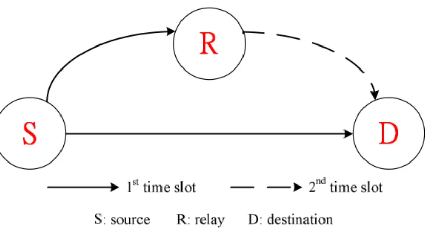
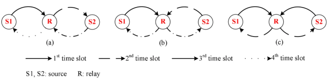
2.1 A one-way relay network: source S transmits its information to the desti-nation D with the help of relay. . . . 7 2.2 A two-way relay network: sources S1 and S2 exchange information with
each other with the aid of the relay. (a) Traditional scheme. (b) TDBC scheme. (c) MABC scheme. . . 8 3.1 A multi-relay two-way network: sources S1 and S2 communicate with
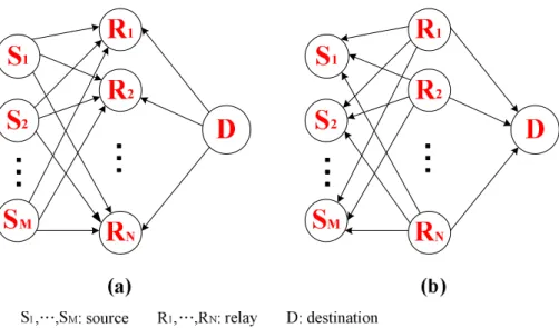
each other with the help of relays. . . 13 3.2 A multi-source multi-relay network. (a) 1st time slot. In this time slot,
each source and destination transmit their information to all relays simul-taneously. (b) 2nd time slot. In this time slot, all relays transmit their regenerated signals to sources S1,..., SM and destination D. . . . 15
3.3 Performance of multi-relay two-way network without multiuser interfer-ence. . . 23 3.4 Comparison of the proposed algorithm to an interference-free case. . . 23 3.5 Performances of multi-relay two-way network with multiuser
interfer-ence. (a) comparison of the number of relays: N = 3 and N = 5. (b) comparison of the number of relays: N = 3 and N = 10. . . . 25 3.6 Performances of multi-relay two-way network with multiuser
interfer-ence. (a) comparison of the number of users: M = 3, M = 6 and M = 9. (b) comparison of the length of spreading sequence: K = 3, K = 7 and
K = 11. . . . 26 3.7 Comparison of the proposed algorithm to random RS method. . . 28
Chapter 1
Introduction
1.1 Motivation
The idea of communications with cooperative relays has attracted much attention recently for the sake of its ability to combat channel fading and to implement an environment of multiple transmit antennas in a distributed fashion. Depending on the number of infor-mation flows, there exist two different communication schemes. One is the unidirectional relay network, and the other is the bidirectional relay network. In unidirectional relay networks, the information is transmitted from one of the end-sources to the other in a sin-gle direction with the help of relay(s). On the other hand, in bidirectional relay networks, two end-sources can exchange information through the relay(s) because information is allowed to transmit in opposite directions. Due to the limited number of information flows, unidirectional relay network requires more time slots to complete the information exchange between two end-sources. Compared with unidirectional relay network, bidi-rectional relay network is more bandwidth efficient. Since bandwidth is a scarce resource in wireless communications, bidirectional relay network is more tempting than unidirec-tional relay network under the consideration of bandwidth efficiency.
There have been considerable research activities putting attention on both relay net-works. The works in [1] and [2] are related to unidirectional relay netnet-works. In [1], the authors presented a tutorial overview of cooperative communications. The authors reviewed several of the main cooperative signaling methods such as detect-and-forward
method, amplify-and-forward approach and coded cooperation. Also, some important challenges and practical issues were introduced. In [2], besides introducing the basic idea of user cooperation, the authors proposed some possible user cooperation schemes and analyzed their throughput based on information-theoretic concepts. The works in [3], [4] and [5] are related to bidirectional relay networks. Both [3] and [4] considered a bidi-rectional relay network in an amplify-and-forward mode. How to allocate power to all relays optimally based on some criteria such as minimizing the conditional pairwise-error-probability of the worst link and maximizing the instantaneously sum rate was discussed. Simulation results in both works showed that full diversity can be achieved in the pro-posed scenarios. In [5], the authors considered a bidirectional multi-relay network which employing distributed space-time coding. Apart from two well-known relaying protocols (e.g. amplify-and-forward and decode-and-forward), a new protocol termed as partial decode-and-forward was proposed where each relay could remove part of the noise from the received signal while keeping the channel effect. That is, the relay could decode the combined received signal from two end-sources rather than decode them separately. The achievable diversity order was analyzed for all above schemes in [5].
When there exist multiple relays in a network, several strategies which utilize mul-tiple relays can be employed. Distributed beamforming [6] [7], distributed space-time coding [4] [5] and relay selection [8] [9] are developed for multi-relay networks. For the first two strategies, the concepts based on maximum ratio combining are applied, thus, each relay node needs to adjust their transmission phases before sending the signal for coherent combining at the receiver. However, it is not the case for relay selection. Nei-ther phase adjustment nor time/frequence synchronization should be required since only a single relay is selected to assist the transmission. For the purpose of simple implemen-tation, relay selection has been widely studied. It is worth noting that the relay selection exhibits excellent performance with full diversity as well. Although relay selection has attracted much attention, still few works investigate multi-user multi-relay networks. And in such studies, how to assign a relay to a pre-determined partner or select the best source-relay pair to access the channel are the main issues [10] [11]. Most works in multi-user multi-relay networks neglect the effect of interference by assuming orthogonal channels.
Although the assumption simplifies the problems, it degrades the bandwidth efficiency of the network. Motivated by this, we tackle a relay selection problem in multi-user two-way cooperative relaying systems in which multi-user interference is involved. Our main goal is to select the best relay based on maximizing the signal to interference-plus-noise ratio (SINR) of the worse link. Furthermore, we investigate a more practical scenario which consists of multiple sources, multiple relays and a destination which the sources and destination can be regarded as the mobile handsets and base station, respectively.
1.2 Contributions of the Research
To the best of our knowledge, there is no work considering the same scenario which consists of multiple users, multiple relays and only a single destination in bidirectional relay network as ours. Nevertheless, the proposed scenario is meaningful. Regarding the multi-source nodes and the destination as mobile handsets and base station, respectively, this scenario is more similar to the communication system in reality compared with those consisting of only one source and one destination. On the other hand, we take multiuser interference into account, which is not considered in the most research work related to multiuser two-way relaying networks. Channel orthogonality is assumed frequently in many studies to avoid interference. However, such assumption is not so realistic and de-grades the bandwidth efficiency. To be closer to reality or more bandwidth efficient, taking the multiuser interference into consideration is necessary. In our work, we consider a code division multiple access (CDMA) system with nonorthogonal spreading sequences.Signal to interference-plus-noise ratio is a benchmark of communication quality. For the sakes of increasing SINR as well as facilitating the implementation, relay selection based on maximizing the SINR of worse link is performed in our work. Besides, aiming at miti-gating the interference, we consider the design of linear filter at each relay as well. The result shows that the linear filter is similar to the minimum mean-squared error detector.
Furthermore, we simulate the proposed scheme with several different parameters such as the number of users and relays, and the length of spreading sequences. Also, we compare the proposed relay selection method with random relay selection approach, and
the result shows that our proposed method has better performance in terms of the bit error rate.
To sum up, the contributions of research include:
• We develop a more realistic scenario in bidirectional relay network consisting of
multiple sources, multiple relays, and one destination.
• Relaxing the constraint of channel orthogonality, we perform relay selection while
taking the multiuser interference into account. Based on the selection criterion that aims at maximizing the signal to interference-plus-noise ratio of the worse link, our proposed scheme outperforms the random relay selection method in terms of the bit error rate.
• The multiuser interference is mitigated by the linear filtering at each relay, which is
Chapter 2
Background Review
2.1 Relay Networks
In wireless communication, several challenges such as limited energy, service coverage and channel impairments caused by multi-path propagation and Doppler shifts should be overcame. Relay networks have been proposed to conquer these difficulties by exploiting the spatial diversity gains without the need of multiple antennas at each node [8] [12]. The basic concepts of relay networks were first introduced in [13]. Cover and El Gamal stud-ied a network which consisted of a source, a destination and a single relay. The focus of this work was on evaluating the channel capacities of the Gaussian relay channel and cer-tain discrete relay channels based on the information theoretic properties. Different from recent works, the analysis of capacity in [13] was an additive Gaussian channel noise, however, fading channel is considered in most recent works [1]. The fundamental trans-mission process of a relay network is as follows. At first time instant, the source sends its information to the relay. The relay then processes the received signals and forwards them to the destination. After properly combining (e.g., maximum ratio combining) the signals sent from the source and relay at the destination, the advantages of the relay com-munication such as spatial diversity can be achieved. In short, the relay comcom-munication is recognized as an effective method to attain broader coverage range and mitigate channel impairments due to fading.
configurations: one-way relay network and two-way relay network. In one-way relay net-works, information is transmitted in a single direction from the source to the destination. However, in two-way relay networks, the information is allowed to transmit in opposite directions such that the two sources can exchange information with the aid of relays. In the following, the concepts of one-way and two-way relay networks will be discussed.
2.1.1 One-Way Relay Networks
The fundamental concept of one-way relay network is that the information can only be transmitted in one direction, i.e., from a source to a destination. A typical one-way relay network consisting of a source, a destination and a single relay is depicted in Fig. 2.1. In Fig. 2.1, the communication is established in two time slots with the aid of the relay node
R. In the first time slot, the source node S broadcasts its symbol to the relay and the
in-tended destination. Upon receiving the signal, the relay processes it based on some kinds of relaying strategies to regenerate a new signal. After that, the relay retransmits the new signal to the destination terminal D in the second time slot to complete the information transmission.
Many relaying strategies have been proposed for relays to execute on their received signals. Some of these techniques are amplify-and-forward (AF), decode-and-forward (DF), compress-and-forward (CF), and estimate-and-forward (EF). Among these approaches, AF and DF are the most well-known ones. In the AF scheme, each relay simply amplifies its received signal and retransmits the amplified signal to the destination, whereas in the DF scheme, each relay should detect the received signal and retransmits the detected sig-nal. Following is an example to demonstrate the regenerated signals at relay nodes in AF and DF schemes.
Example [12]
Consider the system model depicted in Fig. 2.1, but the direct link (i.e., S-D link) does not exist for simplicity. In the first time interval, source S transmits its symbol xsto the
relay node R. The received signal at the relay can be expressed as
Figure 2.1: A one-way relay network: source S transmits its information to the destination
D with the help of relay.
where h is the channel coefficient for S-R link, and n denotes the additive noise. In the second time interval, the relay regenerates a new signal xr = f (yr) and transmits it to the
destination. The function f (·) stands for different relaying strategies. In AF scheme, xr
can be presented as
xr = βyr (2.2)
where β is an amplified coefficient. However, it is not the case for DF scheme. If DF strategy is employed, xr can be shown as
xr = ˆxs (2.3)
where ˆxsis the decoded symbol of xs.
All in all, the AF approach is more simpler than the DF method because signal de-tection does not be needed at each relay in the AF approach. Therefore, the DF method requires more processing power at the relays compared to the AF approach. There have been a lot of works done on AF and DF relaying schemes. Although different strate-gies are performed at relays, spatial diversity can be achieved for both relaying schemes because of the reason that independent replicas of the source signal are received by the destination if the direct link exists.
Figure 2.2: A two-way relay network: sources S1and S2exchange information with each
other with the aid of the relay. (a) Traditional scheme. (b) TDBC scheme. (c) MABC scheme.
2.1.2 Two-Way Relay Networks
In many applications of relay networks, two end-sources may need to exchange informa-tion with the aid of relays. The concept of two-way channels can be traced back to the work of C. E. Shannon in 1961. Shannon obtained an inner bound and an outer bound to the rate region for a full-duplex scenario. However, no relay node existed in Shannon’s work at that time. When the distance between two end-sources is so long that the direct link between them is not available or when the channel quality between two end-sources is poor, the communication between two end-sources is unreliable. Assisted by relays, a more trustworthy communication can be established between two end-sources.
Since two-way relay network is more bandwidth efficient than one-way relay network, it has received considerable attention recently. Several two-way relay network protocols have been proposed: the traditional technique, the time division broadcast (TDBC) proto-col and the multiple access broadcast schemes (MABC). A typical two-way relay network consisting of two end-sources and one relay is depicted in Fig. 2.2. As shown in Fig. 2.2 (a), a traditional two-way relay network requires four time slots to accomplish the infor-mation exchange between the two end-sources. In the first time slot, source S1 broadcasts
its symbol to the relay. Then, the relay retransmits a new signal to source S2in the second
time slot after performing some kinds of relaying strategies at the received signal. In the third and fourth time slots, the same procedures in the first two time slots are conducted again. However, the information flow is from source S2to source S1. Consequently, this
traditional scheme is not bandwidth efficient. As shown in Fig. 2.2 (b), the TDBC proto-col based on the concept of network coding reduces the number of time slots to three. In the first two time slots, sources S1 and S2transmit their symbols to the relay sequentially.
It is worth noting that the relay has to decode the received symbols and perform an XOR operation on the decoded signals before retransmitting a new signal to sources S1 and S2.
In other words, if the transmitted symbols by sources S1 and S2 are xs1 and xs2, then the
regenerated signal at the relay can be expressed as xr = ˆxs1 ⊕ ˆxs2, where ˆxs1 and ˆxs2
denote the decoded symbols of xs1 and xs2, respectively. As a result, each source can
retrieve its desired signal easily by performing an XOR operation on the received signal and its transmitted signal. Since the concept of network coding is used, the TDBC scheme provides a throughput which is significantly higher than the traditional relaying scheme. The MABC schemes are shown in Fig. 2.2 (c). There are two well-known protocols in the MABC schemes: the analog network coding (ANC) [14] and the physical-layer network coding (PNC) [5] [15]. For both protocols, two time slots are required to ac-complish the information exchange between the two end-sources. In the first time slot, the two end-sources transmit their signals to the relay simultaneously. In the second time slot, the relay retransmits the mixed version of two incoming signals. Compared with the TDBC protocol, the MABC schemes have better bandwidth efficiency. However, under a half-duplex constraint, the MABC schemes can not utilize the direct link between two end-sources even if the link exists. To sum up, the MABC schemes are more bandwidth efficient while the TDBC protocol can offer more reliable communication quality than the MABC schemes because of the utilization of the direct link. For example, in Fig. 2.2, the diversity order of the MABC schemes is one while that of the TDBC protocol is two under a half-duplex constraint.
2.2 Relay Selection
When multiple relays exist in the network, several strategies which utilize multiple re-lays are developed to achieve some desired goals. Those strategies including power al-location [3] [10], distributed beamforming [6] [7], distributed space time coding [5] and
relay selection (RS) [8] [9] are widely studied in the literature. Some challenges will be encountered when all relays participate in relaying. One of the problems is the interfer-ence. Most of the works assume that the relays transmit on orthogonal channels such that the interference can be avoided. However, this assumption reduces the capacity of the network. Relaxing the orthogonality constraint can increase the capacity while the implement complexity is raised as well. On the other hand, ideal frequency or time syn-chronization across the relays should be taken into consideration if all relays are used in the network. RS has been proposed and recognized as an effective method to over-come these difficulties. Because of its ability to facilitate the system design and achieve full diversity with less synchronization requirement and overhead, RS has attracted much attention. Some works which relate to RS are introduced in the following paragraphs.
RS has been studied extensively for a one-way relay network consisting of a source, a destination, and multiple relays. One most commonly used RS strategy is to select a sin-gle best relay based on different objectives. In [16], a selective relaying scheme based on signal-to-noise-ratio (SNR) to minimize the end-to-end bit error rate (BER) in cooperative digital relaying systems using BPSK modulation was studied. In the SNR-based selective relaying, the relay either retransmitted or remained quiet depending on the SNRs of all links in the network. Among all relays whose received SNRs were larger than a thresh-old would participate in relaying. In addition, approximations for the optimal threshthresh-old values that minimized the end-to-end BER and the resulting performance were derived. Also, the authors found that the optimal threshold was independent of the average source-relay SNR. Bletsas et al. developed and analyzed a distributed method to select the best relay on local channel measurements of the instantaneous channel conditions [17]. Two different selective policies were considered and represented as follows:
• Policy I hi = min {|asi|2, |aid|2} (2.4) • Policy II hi = 2|asi|2|aid|2 |asi|2+ |aid|2 (2.5)
where asi and aid described the quality of the path between source-relay-destination for
each relay i. The relay i that maximized function hiwas the one with the best end-to-end
path quality and would be selected. Furthermore, it indicated that there was no loss in performance if only the best relay participated in cooperation in orthogonal cooperative diversity protocols. Moreover, Bletsas et al. showed that no mater what kind of strategy was applied, the single RS can achieve full spatial diversity order as if all relays were used.
As in the one-way relay networks, RS can be applied to the two-way relay networks when there exist multiple relays. Since the concept of two-way relay networks was pro-posed recently, the amount of works is small compared with that in one-way relay net-works. Relay selection for bidirectional relaying was first introduced in [9]. Oechtering
et al. considered a system using superposition encoding at relay nodes. The RS criterion
was to maximize the weighted sum rate for any bidirectional rate pair on the boundary of the achievable rate region. Oechtering et al. showed that in the case of independent and identical distribution (i.i.d) Rayleigh fading, RS could achieve the same diversity order as distributed beamforming. In [14], RS with ANC and TDBC in AF-based bidirectional relay networks was studied. The RS was based on a max-min criterion to minimize the outage probabilities and could be expressed as
ˆl= arg max l=1,...,Lmin £ I1,l, I2,l ¤ (2.6) where L was the number of relays, I1,l and I2,l denoted the mutual information of two
opposite traffic flows for the l-th relay-path from source S1 via relay l to source S2 and
from S2 via relay l to S1, respectively. That is, a relay which maximized min
£
I1,l, I2,l
¤ over all the relays would be selected.
Chapter 3
Relay Selection in Multiuser Two-Way
Cooperative Relaying Systems
3.1 Problem Setup
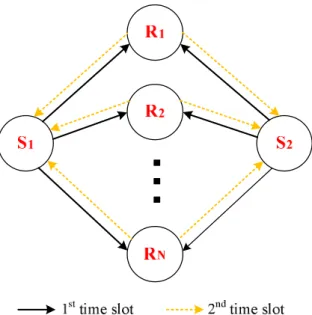
Relay communication has received a great amount of attention because it is recognized as an effective technique to mitigate channel impairments. A typical multi-relay two-way network consisting of two sources and multiple relays is depicted in Fig. 3.1. Two sources
S1 and S2 can exchange information with the help of relays. Recently, some studies have
taken the issue of multi-source into account. In [18], the authors considered a network consisting of m pairs (i.e., m two-way relay channels) and n relay nodes. How to assign the relay node to each pair in conjunction with network coding was the main problem addressed in [18]. In [10], a two-way multi-relay multi-user network with amplify-and-forward relaying strategy was considered. The authors showed the algorithms to deal with the power allocation problem by maximizing the instantaneous sum rate and mini-mizing the symbol error rate when the multi-user interference can be ignored by a channel assignment algorithm. In our work, the system model is similar to [11]. A network con-sisting of multiple sources, multiple relays and a single destination is presented in both works. However, the considered scenarios and problems are different. First, the infor-mation flow is unidirectional in [11] but bidirectional in our work. Second, in [11], the authors proposed a joint selection scheme that selected the best source-relay pair to access
Figure 3.1: A multi-relay two-way network: sources S1 and S2 communicate with each
other with the help of relays.
the channel in the network. However, it is not the case in our work. The issues that we are interested in are how to deal with the multi-user interference and select the best relay based on some criteria to achieve the best performance in terms of SINR for the network. To the best of our knowledge, most of the research activies related to relay communica-tion were interference-free. These studies ignored the effect of interference by assuming channel orthogonality. Only a few of works took multi-user interference into considera-tion [19], [20]. In [19], the authors considered a simple ad-hoc configuraconsidera-tion consisting of two neighboring clusters and the target was to analyze the inter-cluster interference. The results showed that the interference changed the statistical description of the conven-tional amplify-and-forward protocol and limited the diversity gain of the system. In [20], a multiuser two-way relay network employing Code Division Multiple Access (CDMA) was considered. The authors proposed a jointly demodulate-and-XOR forward relaying scheme. In phase one, all users transmitted their symbols to the relay simultaneously. The relay broadcasted an estimate of XORed symbol for each user pair in phase two. The decision rules and the corresponding bit error rate at the relay and each user node were derived. And the authors dealt with the power control problem and receiver optimization
problem for each phase. Except for different scenarios and relaying strategies applied, the main difference between [20] and our work is that the most important problem in our work is to do relay selection (RS) while there is no RS in [20] because of only a single relay node therein. To sum up, a multi-source multi-relay bidirectional relay network employing CDMA is considered in our research. The problems we try to solve are to mitigate interference and perform relay selection such that the best performance in terms of SINR can be achieved.
Notations
We use uppercase and lower case boldface letters to represent matrices and vectors, re-spectively. Complex conjugate, transpose, and Hermitian transpose are represented by (·)∗, (·)T and (·)H, respectively. We use E{·} to denote statistical expectation. We denote
the identity matrix by I and 0 to represent all-zero vectors or matrices.
3.2 System Model
We consider a multi-user multi-relay two-way relaying network which consists of M sources, N relays and a single destination as shown in Fig. 3.2. The sources and destina-tion can be seen as the mobile handsets and base stadestina-tion, respectively. There are no direct links between the sources and the destination because of the poor quality of channels. We use the amplify-and-forward (AF) relaying protocol with RS. The information exchange between all end-nodes is completed in two time slots. In the first time slot, all sources and destination transmit to all relays simultaneously. After performing the AF relaying strat-egy, the selected relay transmits a new signal to all sources and the destination. In order to accommodate the communication of multiple users simultaneously, direct sequence (DS)-CDMA is employed. Taking the effect of interference into consideration, we assume that the signatures are nonorthogonal. For convenience, we take the source S1 as the desired
user and other users S2to SM as interference. All nodes in the network are single antenna
units and half-duplex such that they can only transmit or receive the signals at a time. We assume a flat-fading scenario and the channel coefficients are complex reciprocal (i.e., the channel coefficients from the ith user/desitination to the jth relay and from the jth
Figure 3.2: A multi-source multi-relay network. (a) 1st time slot. In this time slot, each source and destination transmit their information to all relays simultaneously. (b) 2nd time slot. In this time slot, all relays transmit their regenerated signals to sources S1,...,
SM and destination D.
relay to the ith user/destination are the same.) The channel gains from the jth relay to the
ith source and destination are denoted as fij and gjD for i = 1, ..., M , and j = 1, ..., N ,
respectively. We assume that all sources and the destination know all channel coefficients
fij and gjD for i = 1, ..., M and j = 1, ..., N and the relay j only knows its local channel
coefficients fij for i = 1, ..., M and gjD.
A. Phase One
During the first time slot, all sources and the destination transmit their signals to the relays simultaneously. The signals received at relay j can be represented as
yRj = M X i=1 √ P fijx(U )i si+ √ P gjD M X i=1 x(D)i si+ nRj (3.1)
where si denotes a K × 1 vector of unit norm spreading sequence. The transmitted
power is P at all source nodes and MP at the destination. x(U )i denotes the transmit-ted symbol for source Si, and x(D)i is the symbol that the destination wants to transmit
E{x(U )i x(U )∗j } = E{x(D)i x(D)∗j } = 0 for i 6= j. nRj is a K × 1 zero mean complex vector
at the jth relay noise with E{nRjnHRj} = σ
2
RjI.
Upon receiving yRj, the relay j employs linear filter cj to obtain yR0 j as
y0 Rj = c H j yRj = M X i=1 √ P fijx(U )i cHj si+ √ P gjD M X i=1 x(D)i cH j si+ cHj nRj (3.2)
where cj is a K × 1 complex vector.
B. Phase Two
During the second time slot, the jth relay regenerates a new signal xRj and transmits it to
all sources and the destination. The new transmitted signal for relay j is
xRj =
q
PRjy
0
Rj (3.3)
where PRj is the power for relay j to amplify the received signals. Actually, assuming
that all information symbols and noises are independent, the total transmit power which relay j requires can be shown as
Pt,Rj = E{xRjx H Rj} = P PRj " M X i=1 ¡ |fij|2|cHj si|2+ |gjD|2|cHj si|2 ¢# + PRjσ 2 Rjc H j cj (3.4)
In our work, we assume that source S1 is the desired user for convenience. Therefore,
we only consider the received signals at source S1 and the destination in the following
discussion. The signal yS1 received at source S1can be expressed as
yS1 = f1jxRj + nS1 = q P PRjf 2 1jx (U ) 1 cHj s1+ q P PRjf1jgjDx (D) 1 cHj s1 +X i6=1 q P PRj ³ f1jfijx(U )i cHj si+ f1jgjDx(D)i cHj si ´ +³qPRjf1jc H j nRj+ nS1 ´ (3.5)
where nS1 is the noise at source S1 with zero mean and variance σ2S1. Consider the
re-ceived signal yD at the destination, it can be represented as
yD = gjDxRj+ nD = M X i=1 q P PRjg 2 jDx(D)i cHj si+ q P PRjf1jgjDx (U ) 1 cHj s1 + X i6=1 q P PRjfijgjDx (U ) i cHj si + ³q PRjgjDc H j nRj + nD ´ (3.6) where nDis the noise at the destination with zero mean and variance σD2. In (3.5), the first
term is known as self-interference and can be subtracted from yS1. The second term is
the desired signal for source S1, the third term is the interference caused by other sources
and the last term represents the noise. Consider the communication between the source
S1 and the destination, similarly, the first term in (3.6) can be subtracted from yD through
self-interference cancelation. The second term is the signal that we are interested in, the third term depicts the interference and the last term is the noise. After canceling the self-interference terms in (3.5) and (3.6), the residual signals ˜yS1 and ˜yD can be shown as
˜ yS1 = q P PRjf1jgjDx (D) 1 cHj s1 + q P PRj X i6=1 ³ f1jfijx(U )i cjsi+ f1jgjDx(D)i cHj si ´ + ³q PRjf1jc H j nRj + nS1 ´ (3.7) ˜ yD = q P PRjf1jgjDx (U ) 1 cHj s1+ q P PRj X i6=1 fijgjDx(U )i cHj si+ ³q PRjgjDc H j nRj + nD ´ (3.8) Therefore, the residual signals ˜yS1 and ˜yD can be used to decode the desired symbols
x(D)1 and x(U )1 at source S1 and the destination, respectively.
3.3 Proposed Algorithm
As mentioned earlier, our goals are to do relay selection and to design the linear filter at each relay based on the maximization of the smaller received SINR of the desired source
S1 and the destination. Taking the interference into account, the SINR is a benchmark of
performance in the communication system intuitively. As a result, we choose the SINR as a selection criterion. The main problem can be represented as
max
cj,j
min (SIN RS1,j, SINRD,j)
subject to 2MP + Pt,Rj ≤ PT
(3.9) where PT is the total available power in the network. The SINRS1,j and the SINRD,j
are denoted as the received SINRs at source S1and the destination due to the transmission
from relay j, respectively. In order to make a clearer derivation, we assume that the noise variances at all nodes are normalized. That is, nS1, nD ∼ CN (0, 1) and nRj ∼ CN (0, I).
By calculating from ˜yS1 and ˜yD, the SINRs can be written as
SIN RS1,j = P PRj|f1j|2|gjD|2|cHj s1|2 P PRj|f1j|2 P i6=1 ¡ |fij|2|cHj si|2+ |gjD|2|cHj si|2 ¢ +¡PRj|f1j|2cHj cj+ 1 ¢ (3.10) SINRD,j = P PRj|f1j| 2|g jD|2|cHj s1|2 P PRj|gjD|2 P i6=1|fij|2|cHj si|2+ ¡ PRj|gjD|2cHj cj + 1 ¢ (3.11) In the following, we divide the optimization problem into two parts and deal with them separately. We firstly optimize (3.9) over cj and then over j to solve the problem.
3.3.1 Design of Linear Filter at Relay Nodes
For optimizing over cj, the problem can be presented as
max
cj
min (SIN RS1,j, SINRD,j) (3.12)
We denote the smaller one between SINRS1,j and SINRD,j as SINRj. It is easily to
show that
SINRj = min (SINRS1,j, SINRD,j)
=
SINRS1,j, if SINRD,j − SINRS1,j ≥ 0;
SINRD,j, if SINRD,j − SINRS1,j < 0.
Consider SINRD,j − SINRS1,j ≥ 0 firstly, we can find the following criterion: SINRD,j− SIN RS1,j ≥ 0 ⇒ P PRj|f1j| 2X i6=1 ¡ |fij|2|cHj si|2+ |gjD|2|cHj si|2 ¢ +¡PRj|f1j| 2cH j cj + 1 ¢ ≥ P PRj|gjD| 2X i6=1 |fij|2|cHj si|2+ ¡ PRj|gjD| 2cH j cj + 1 ¢ ⇒ P |fij|2 X i6=1 ¡ |fij|2|cHj si|2+ |gjD|2|cHj si|2 ¢ + |fij|2cHj cj ≥ P |gjD|2 X i6=1 |fij|2|cHj si|2+ |gjD|2cHj cj ⇒ P |fij|2 X i6=1 ¡ |fij|2cHj sisHi cj+ |gjD|2cHj sisHi cj ¢ + |f1j|2cHj cj ≥ P |gjD|2 X i6=1 |fij|2cHj sisiHcj + |gjD|2cHj cj ⇒ cH j ( P |f1j|2 " X i6=1 ¡ |fij|2sisHi + |gjD|2sisHi ¢ + |f1j|2I #) cj ≥ cHj à P |gjD|2 X i6=1 |fij|2sisHi + |gjD|2I ! cj (3.14)
From the derivation above, we know that min (SINRS1,j, SINRD,j) = SINRS1,j if it
satisfies A , P X i6=1 ¡ |f1j|2|fij|2+ |f1j|2|gjD|2− |gjD|2|fij|2 ¢ sisHi + ¡ |f1j|2− |gjD|2 ¢ I < 0 (3.15) In other words, if matrix A is positive semi-definite, then min(SINRS1,j, SINRD,j) =
SINRS1,j, otherwise min(SIN RS1,j, SINRD,j) = SINRD,j. From [21], we know one
of the properties of positive semi-definite matrices is as follows.
Property 1 (Box3.1 in [21]) A Hermitian matrix is positive semi-definite (p.s.d) if and
only if all of the eigenvalues are nonnegative.
Since A is a Hermitian matrix, we can simply tackle (3.15) by checking its eigenvalues. Taking (3.15) into (3.13), the linear filter cj can be designed for SINRj = SINRS1,j
• When matrix A is p.s.d (i.e., SINRj = SINRS1,j), (3.12) can be reduced to max cj SINRS1,j (3.16) where SINRS1,j = P PRj|f1j| 2|g jD|2|cHj s1|2 P PRj|f1j|2 P i6=1 ¡ |cH j si|2+ |gjD|2|cHj si|2 ¢ +¡PRj|f1j|2c H j cj+ 1 ¢ = P PRj|f1j| 2|g jD|2cHj s1sH1 cj P PRj|f1j|2 P i6=1 ¡ |fij|2cHj sisHi cj + |gjD|2cHj sisHi cj ¢ +¡PRj|f1j|2cHj cj + 1 ¢ ≈ P |f1j| 2|g jD|2cHj s1sH1 cj P |f1j|2 P i6=1 ¡ |fij|2cHj sisHi cj + |gjD|2cHj sisHi cj ¢ + |f1j|2cHj cj = c H j ¡ P |gjD|2s1sH1 ¢ cj cH j h PPi6=1(|fij|2+ |gjD|2) sisHi + I i cj (3.17) where the approximation in (3.17) is rational by assuming the effect of noise (i.e., factor 1 in the denominator) at source S1 can be ignored in high SNR regimes. By
modifying (3.17), the problem in (3.16) is rewritten as min cj cH j h P Pi6=1(|fij|2+ |gjD|2) sisHi + I i cj cH j (P |gjD|2s1sH1 ) cj (3.18) Similar derivation procedure as in [22], the linear filer cj can be found as
cj = " P X i6=1 ¡ |fij|2 + |gjD|2 ¢ sisHi + I #−1 √ P gjDs1 (3.19)
• On the other hand, when matrix A is not p.s.d (i.e., SINRj = SINRD,j), (3.12) is
reduced to
max
cj
SIN RD,j (3.20)
The same approximation in the first case is used, we can obtain the SINRD,j as
SINRD,j = P PRj|f1j| 2|g jD|2|cHj s1|2 P PRj|gjD|2 P i6=1|fij|2|cHj si|2+ ¡ PRj|gjD|2cHj cj+ 1 ¢ = P PRj|f1j|2|gjD|2|cHj s1sH1 cj P PRj|gjD|2 P i6=1|fij|2|cHj sisHi cj|2+ ¡ PRj|gjD|2cHj cj + 1 ¢ ≈ P |f1j| 2|g jD|2|cHj s1sH1 cj P |gjD|2 P i6=1|fij|2|cHj sisHi cj|2+ |gjD|2cHj cj = c H j ¡ P |f1j|2s1sH1 ¢ cj cH³P P |f |2ssH + I´c (3.21)
Performing the similar derivation as in the first case, the linear filter cj can be found as cj = " P X i6=1 |fij|2sisHi + I #−1 √ P f1js1 (3.22)
To sum up, the linear filter at relays can be designed depending on matrix A as follows: cj = h PPi6=1(|fij|2+ |gjD|2) sisHi + I i−1√ P gjDs1, if matrix A is p.s.d; cj = h P Pi6=1|fij|2sisHi + I i−1√ P f1js1, otherwise. (3.23) As can be observed from (3.23), the linear filter cj maximizes SINRj and is similar to
minimum mean-square error (MMSE) detector.
3.3.2 Relay Selection
With the linear filter cj found for two different cases, the problem in (3.9) is reduced to
the following RS problem:
max
j∈{1,...,N }SINRj (3.24)
The steps in conducting relay selection are as follows. The destination which knows all channel coefficients and the spreading sequences for different sources can select the optimum relay by calculating SINRj for j = 1, ..., N . First, the destination can examine
the criterion in (3.15) to decide which one of SIN RS1,jand SINRD,j is smaller for each
relay. Second, upon knowing which is the smaller one, the destination calculates the filter cj and SINRj for j = 1, ..., N . Comparing all SINRs, the destination picks up the relay
which results in the maximum SINR. Then, the destination broadcasts the best relay index to all relays over a control channel. Here, we assume the relays resemble base station, thus, they are capable of knowing all spreading sequences for different users. Therefore, the one hears its index can employ linear filer to obtain a new signal and transmit it, others do not hear their own indices will be quiet and not participate in relaying.
3.4 Simulation Results
3.4.1 Simulation Setup
In this section, we present some numerical results to demonstrate the performance in terms of BER of our proposed algorithm. A multiuser two-way relay network employing CDMA is considered. The digital modulation used here is quadrature phase shift keying (QPSK). To best of our knowledge, the scenario in this work has not been discussed, hence no comparison between other studies and ours is made in the simulations. Here, we focus on simulating the effects of different parameters (e.g., the number of sources, the number of relays and the length of spreading sequences) in the network. The channel coefficients
fij and gjD for i = 1, ..., M and j = 1, ..., N in the simulations are generated as zero
mean normal complex random variables with unit variance (i.e., fij, gjD ∼ CN (0, 1)).
All noises at each node are assumed to be i.i.d Gaussian with zero-mean and unit variance (i.e., nS1, nD ∼ CN (0, 1) and nRj ∼ CN (0, I)). The spreading sequences are K × 1
vectors with unit norm and generated randomly. All spreading sequences for different sources are assumed to be non-orthogonal. Noting that the power assumption here is presented in [23]. Let all nodes except the relays use half of total available power, and the remaining half power is used for the selected relay to transmit. Therefore, 2MP = 0.5PT and Pt,Rj = 0.5PT. Parameters M and N denote the number of users and relays,
respectively. Parameter K stands for the length of spreading sequences.
3.4.2 Effectiveness of Proposed Algorithm
The effects of different parameters are presented in the following simulation results. In each figure, BERS1 and BERD denote the bit error rates at the desired user S1 and the
destination, respectively. A. Number of Users
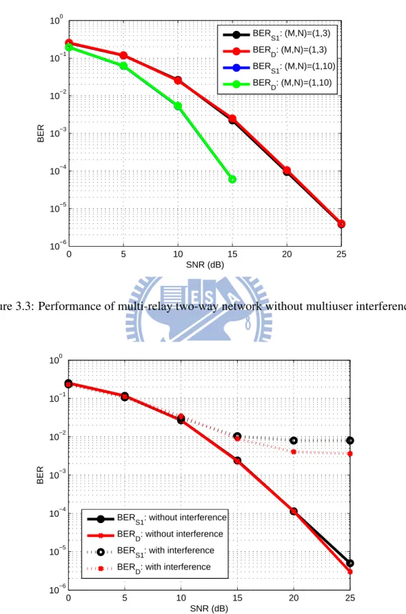
Fig. 3.3 depicts the performance of a single-user multi-relay two-way relaying network in terms of BER. It can be seen as the special case of multiuser relay network, i.e., the
0 5 10 15 20 25 10−6 10−5 10−4 10−3 10−2 10−1 100 SNR (dB) BER BER S1: (M,N)=(1,3) BER D: (M,N)=(1,3) BER S1: (M,N)=(1,10) BER D: (M,N)=(1,10)
Figure 3.3: Performance of multi-relay two-way network without multiuser interference.
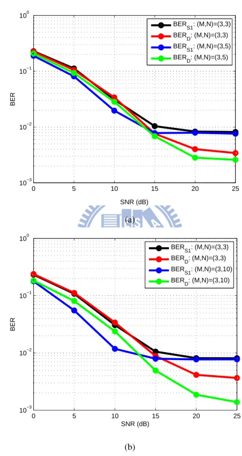
0 5 10 15 20 25 10−6 10−5 10−4 10−3 10−2 10−1 100 SNR (dB) BER BER S1: without interference BER D: without interference BER S1: with interference BER D: with interference
number of users is one. Since no multiuser interference exists in the network, the only factor to degrade the performance of the system is noise. Thus, the curves in Fig.3.3 can be regarded as lower bounds for our work which take interference into consideration with different numbers of relays. In Fig. 3.3, we make a comparison between different number of relays N = 3 and N = 10 with the length of spreading sequence being seven. It shows that the diversity order increases with the number of relays. That is, the diversity order will be larger if there exist more relays in the network.
Fig. 3.4 shows the comparison of our proposed algorithm to an interference-free case (i.e., the number of user is one). As expected, the interference-free case is a lower bound for our work. Because of the effect of interference, full diversity order can not be achieved in our study. In other words, the BER does not decrease with the increase of SNR in our scheme since there is an error floor in high SNR regimes induced by interference. However, it is not the case for interference-free case, full diversity order can be achieved in this ideal scheme.
B. Number of Relays
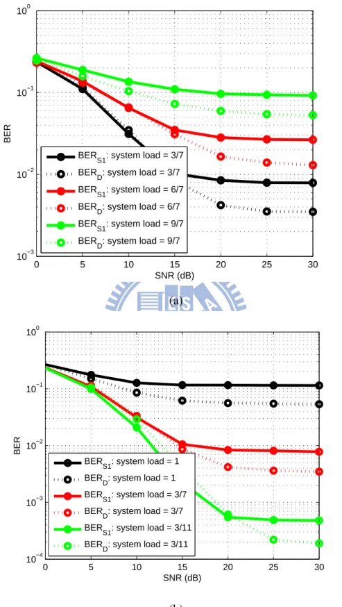
The simulation environment of this part is as follows: the number of users is 3, the length of spreading sequences is 7, and the number of relays is 5 in Fig. 3.5 (a) but 10 in (b). As expected, although full diversity order can not be achieved, the BER still decreases with an increase of SNR. Moreover, it is interesting to find that BER at the desired user
S1 encounters an error floor at SNR 15 dB when there exist 10 relays in the network. As
a result, even more relays exist in the network, the BER at the destination when there exist 5 relays is still better than the BER at the desired user S1when there exist 10 relays
in the network. One of the possible reasons may be the destination node can get more benefits from the self-interference cancelation compared to the node S1. And in high
SNR regimes, the effect of interference dominates the performance, thus, the interference mitigation is more important.
0 5 10 15 20 25 10−3 10−2 10−1 100 SNR (dB) BER BER S1: (M,N)=(3,3) BER D: (M,N)=(3,3) BER S1: (M,N)=(3,5) BER D: (M,N)=(3,5) (a) 0 5 10 15 20 25 10−3 10−2 10−1 100 SNR (dB) BER BER S1: (M,N)=(3,3) BER D: (M,N)=(3,3) BER S1: (M,N)=(3,10) BER D: (M,N)=(3,10) (b)
Figure 3.5: Performances of multi-relay two-way network with multiuser interference. (a) comparison of the number of relays: N = 3 and N = 5. (b) comparison of the number of
0 5 10 15 20 25 30 10−3 10−2 10−1 100 SNR (dB) BER BER S1: system load = 3/7 BER D: system load = 3/7 BER S1: system load = 6/7 BER D: system load = 6/7 BER S1: system load = 9/7 BER D: system load = 9/7 (a) 0 5 10 15 20 25 30 10−4 10−3 10−2 10−1 100 SNR (dB) BER BER S1: system load = 1 BER D: system load = 1 BER S1: system load = 3/7 BER D: system load = 3/7 BER S1: system load = 3/11 BER D: system load = 3/11 (b)
Figure 3.6: Performances of multi-relay two-way network with multiuser interference. (a) comparison of the number of users: M = 3, M = 6 and M = 9. (b) comparison of
C. System Load
In CDMA system, system load is a benchmark parameter which stands for the perfor-mance of the system. Larger system load leads to the worse perforperfor-mance. The definition of the system load is
system load = M
K (3.25)
where M is the number of users and K is the length of spreading sequences. In this part, we make a comparison of the effect of different system loads. In Fig 3.6 (a), different numbers of users are compared. The simulation environment of Fig. 3.6 (a) is as follows: the numbers of users are 3, 6, and 9; the length of spreading sequences is 7; the number of relays is 3. The result shows that the existence of more users in the network degrades the performance. On the other hand, in Fig. 3.6 (b), different lengths of spreading sequences are compared. The simulation environment of Fig. 3.6 (b) is as follows: the number of users is 3; the lengths of spreading sequences are 3, 7, and 11; the number of relays is 3. According to the result, it indicates that the BER performance is better when the length of spreading sequence is longer. To conclude, the simulation results in Fig. 3.6 exhibit that the BER performance is better when the system load is smaller.
D. Different RS Methods
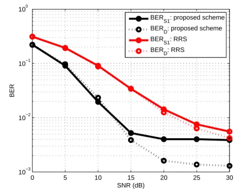
In this part, we compare our proposed algorithm with random RS method. The simulation environment of Fig. 3.7 is as follows: the number of users is 2; the length of spreading sequences is 7; the number of relays is 4. Random RS technique means that the selection is conducted randomly without any criterion. The result in Fig. 3.7 shows that the pro-posed algorithm is much better than random RS approach in terms of BER. In high SNR regimes, the proposed algorithm outperforms the random RS method in terms of SNR by around 15 dB. It indicates that our proposed algorithm offers a selection gain indeed.
0 5 10 15 20 25 30 10−3 10−2 10−1 100 SNR (dB) BER BER S1: proposed scheme BER D: proposed scheme BER S1: RRS BER D: RRS
Chapter 4
Conclusion and Future Work
4.1 Conclusion
We have investigated the problem of RS in multiuser two-way cooperative relaying sys-tems. For the sakes of its abability to facilitate the system design and achieve the full diversity order with less synchronization requirement and overhead, RS has been widely studied in the literature. However, most works on RS considered a one-way or two-way relay network which there existed a single user only. Although some works took the is-sue of multiuser into account, their focuses were usually on how to assign relays to the different pre-determined source pairs or to do source-relay pair selection. Channel or-thogonality was often assumed to avoid the interference in multiuser networks. Different from most studies, we perform RS while taking the multiuser interference into considera-tion. When multiuser interference can not be neglected, intuitively, SINR is an indication of performance. Therefore, the RS approach in proposed scheme is based on max min SINR criterion. In addition, a new scenario in two-way AF-based relaying network which is never considered before is proposed. The proposed scenario is meaningful since it presents a more realistic system model. In this scheme, there exist multiple sources, mul-tiple relays, and a single destination. Moreover, designing the linear filter cj at each relay
for j = 1, ..., N is also an important part of the work. The derivation result shows that the designed filter cjis similar to MMSE detectors, thus, it indicates that the linear filter cjis
Furthermore, in the simulation results, we exhibit the effectiveness of the proposed scheme with several different parameters such as the numbers of users and relays, and the length of spreading sequences. Also, we compare the proposed algorithm with random RS method. The result shows that the proposed algorithm outperforms the random RS method in terms of SNR by around 15 dB in high SNR regimes. To conclude, the proposed algorithm is an effective method to mitigating the interference while doing RS in multiuser multi-relay two-way relaying networks.
4.2 Future Work
In this work, although we have proposed an effective RS algorithm to mitigate the mul-tiuser interference, the performance such as BER and outage probability has not been analyzed. Making the derivation of the performance will complete the work, and the result can be used as another choice of the criterion for RS. Besides, as shown in the sim-ulation results, an error floor due to interference exists in high SNR regimes. Therefore, developing an algorithm which overcomes the presented performance limitation seems to be an promising issue.
As for multiuser two-way relaying systems employing CDMA, the future work might include power control. Power control is a critical problem in CDMA system because of near-far effect. If power control is not done in the system, the users with larger signal power tend to dominate the system, thus, the users with smaller power get worse perfor-mance. However, for simplicity, power control is out of scope in this work. In order to suppress the multiuser interference further and to achieve the better performance, how to perform power control is important in the future work.
Furthermore, developing a RS method to balance the received SINR might be an issue in the future work. As displayed in the simulation results, we can find that BER at the destination is much smaller than BER at the desired source node due to self-interference cancelation. Since more self-interference can be eliminated at the destination, it achieves more benefits from the operation compared to the desired source node. Therefore, it seems a little unfair to select a best relay based on max min criterion. Considering a RS method
that balance the SINR on both the desired source node and the destination might be an approach to promote the performance.
Bibliography
[1] A. Nosratinia, T. Hunter, and A. Hedayat, “Cooperative Communication in Wireless Networks,” IEEE Communications Magazine, vol. 42, pp. 68–73, 2004.
[2] A. Sendonaris, E. Erkip, and B. Aazhang, “User Cooperative Diversity Part I: Sys-tem Description,” IEEE Trans. Commun., vol. 51, no. 11, pp. 1927–1938, Nov. 2003.
[3] Xiao Juan Zhang and Yi Gong, “Adaptive Power Allocation in Two-Way Amplify-and-Forward Relay Networks,” Proceeding of the IEEE ICC’09, pp. 1–5, 2009. [4] Wenjin Wang, Shi Jin, Xiqi Gao, Kai-Kit Wong, and Matthew R. McKay, “Power
Allocation Strategies for Distributed Space-Time Codes in Two-Way Relay Net-works,” IEEE Trans. Signal Processing, vol. 58, no. 10, pp. 5331–5339, Oct. 2010. [5] Tao Cui, Feifei Gao, Tracey Ho, and Arumugam Nallanathan, “Distributed
Space-Time Coding for Two-Way Wireless Relay Networks,” IEEE Trans. Signal
Process-ing, vol. 57, no. 2, pp. 658–670, Feb. 2009.
[6] J. Joung and A. H. Sayed, “Multiuser Two-Way Relaying Method for Beamforming Systems,” Proceeding of IEEE SPAWC’09, pp. 280–284, June 2009.
[7] Veria Havary-Nassab, Shahram Shahbazpanahi, and Ali Grami, “On Relay Assign-ment in Network-Coded Cooperative Systems,” IEEE Trans. Signal Processing, vol. 58, no. 3, pp. 1238–1250, Mar. 2010.
[8] MinChul Ju, “Relay Selection in Two-Hop Wireless Communications,” Doctoral
[9] Tobias J. Oechtering and Holger Boche, “Bidirectional Regenerative Half-Duplex Relaying Using Relay Selection,” IEEE Trans. Wireless Commun., vol. 7, no. 5, pp. 1879–1888, May 2008.
[10] Ted C.-K. Liu, Wei Xu, Xiaodai Dong, and Wu-Sheng Lu, “Adaptive Power Alloca-tion for BidirecAlloca-tional Amplify-and-Forward Multiple-Relay Multi-User Networks,”
Proceeding of IEEE Globecom, pp. 1–6, 2010.
[11] Li Sun, Taiyi Zhang, Long Lu, and Hao Niu, “On the Combination of Cooperative Diversity and Multiuser Diversity in Multi-source Multi-Relay Wireless Networks,”
IEEE Signal Processing Lett., vol. 17, no. 6, pp. 535–538, June 2010.
[12] Yao-Win Hong, Wan-Jen Huang, Fu-Hsuan Chiu, and C.-C. Jay Kuo, “Coopera-tive Communications in Resource-Constrained Wireless Networks,” IEEE Signal
Processing Magazine, vol. 24, no. 3, pp. 47–57, May 2007.
[13] T. M. Cover and A. A. E. Gamal, “Capacity Theorems for the Relay Channel,” IEEE
Trans. Inform. Theory, vol. 25, no. 5, pp. 572–584, Sep. 1979.
[14] MinChul Ju and Il-Min Kim, “Relay Selection with ANC and TDBC Protocols in Bidirectional Relay Networks,” IEEE Trans. Commun., vol. 58, no. 12, pp. 3500– 3510, Dec. 2010.
[15] Petar Popovski and Hiroyuki Yomo, “Physical Network Coding in Two-Way Wire-less Relay Channels,” Proceedings of IEEE ICC’07, pp. 707–712, 2007.
[16] Furuzan Atay Onat, Abdulkareem Adinoyi, Yijia Fan, Halim Yanikomeroglu, John S. Thompson, and Ian D. Marsland, “Threshold Selection for SNR-based Se-lective Digital Relaying in Cooperative Wireless Networks,” IEEE Trans. Wireless
Commun., vol. 7, no. 11, pp. 4226–4236, Nov. 2008.
[17] Aggelos Bletsas, Ashish Khisti, David P. Reed, and Andrew Lippman, “A Simple Cooperative Diversity Method Based on Network Path Selection,” IEEE J. Select.
[18] Xuehua Zhang, Ali Ghrayeb, and Mazen Hasna, “On Relay Assignment in Network-Coded Cooperative Systems,” IEEE Trans. Wireless Commun., vol. 10, no. 3, pp. 868–876, Mar. 2011.
[19] Ioannis Krikidis, John S. Thompson, Steven McLaughlin, and Norbert Goertz, “Max-Min Relay Selection for Legancy Amplify-and-Forward Systems with Inter-ference,” IEEE Trans. Wireless Commun., vol. 8, no. 6, pp. 3016–3027, June 2009. [20] Min Chen and Aylin Yener, “Multiuser Two-Way Relaying: Detection and
Inter-ference Management Strategies,” IEEE Trans. Wireless Commun., vol. 8, no. 8, pp. 4296–4305, Aug. 2009.
[21] Todd K. Moon and Wynn C. Stirling, Mathematical Methods and Algorithms for
Signal Processing, Prentice Hall, 2000.
[22] S. Ulukus and R. D. Yates, “Adaptive power control and MMSE interference sup-pression,” ACM Wireless Networks, vol. 4, no. 6, pp. 489–496, Nov. 1998.
[23] Saurabh Talwar, Yindi Jing, and Shahram Shahbazpanahi, “Joint Relay Selection and Power Allocation for Two-Way Relay Networks,” IEEE Signal Processing Lett., vol. 18, no. 2, pp. 91–94, Feb. 2011.