Architecture Design and Performance Evaluation of RFID Object Tracking Systems
6
0
0
全文
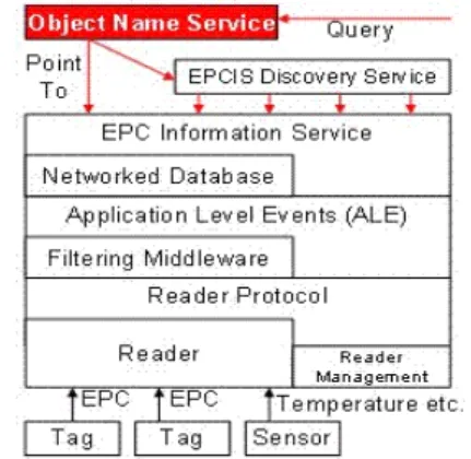
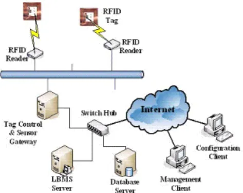
(2) the popularity of this technology got lately. To compete with the cheapest bar-code technology, electronic identification technology must be equally inexpensive, or add adequate added value to improve its applications [11,12]. This study surveys RFID theories and their applications, and the challenges for organizations that deploy this technology.. RFID reader network and a system network, and the RFID reader and the system networks are connected by a bridge. The RFID reader network links wired/wireless readers within a Hospital to track all interesting objects, while the system network connects the main database server, the existing information server (EIS) designed for their hospital and the web server. This architecture is herein called a bridge-based network.. 2.1 RFID System Applications Philips provided a significant RFID application is for the 2006 FIFA World Cup in Germany. The contactless smart card technology named MIFARE is an RFID system deployed for stadium management. The benefits of MIFARE infrastructure include easier and safer access control, as well as support for additional services such as loyalty rewards and e-purse capability. To prevent incidents at the World Cup matches in Germany, more than three million tickets were chipped with RFID for security. Potential hooligans, ticket scalpers, and troublemakers at World Cup matches can thus be identified from the attendees [13]. Although the RFID applications have a great variety to popularize, the RFID system architecture could always be composed of three basic components: RFID tags, RFID readers and backend systems. Figure 2 shows the RFID system architecture. Passive RFID tags are powered by the readers and transfer specific information or change status in response. The operations between RFID tags and readers are quite simple while the most complex procedures are implemented in the backend system. Many researches about RFID are devoted to the development of backend system such as software architecture, middleware and platform integration [14-16].. Figure 3: Integrated Health Delivery Network Architecture 2.2.2 RFID LOCATION-BASED MEDICARE SERVICE SYSTEM The other RFID network system referencing to the RFID project in Taiwan hospital is named Location-Based Medicare Service (LBMS). Its system architecture is shown in Figure 4. Alike to common RFID system, the LBMS system employs RFID readers in tracking tagged persons or objects. Information stored in RFID tags acquired by readers would be transformed into the records to join in the relational database. A gateway component which collects messages from readers and controls RFID devices attaching to it is embedded into the LBMS RFID system. Joining in the operation of other information service in system, the gateway manages collected RFID information and communicates with the database server and LBMS Server. It is possible that more functions are integrated in the gateway to enhance the power and the performance of LBMS RFID system.. Figure 2: RFID System Architecture. 2.2 RELATED RESEARCHES This section surveys two RFID network systems, namely, the RFID network system designed for tracking patients and medical equipment [18], and an RFID project in a Taiwanese hospital [19]. 2.2.1 INTEGRATED RFID HEALTH DELIVERY NETWORK SYSTEM Figure 3 shows the architecture of the Integrated RFID Health Delivery Network, which was designed as a tracking system to bring a patient from the emergency room to a health care facility. The system consists of an. Figure 4: RFID Location-Based Medicare Service. 3 RFID OBJECT TRACKING SYSTEM. - 766 -.
(3) Figure 5 shows the operation of an RFID Object Tracking System in a library. The library system can track the physical location of a man by locating the RFID tag. Since RFID readers are deployed within the building, the library system had constructs the physical location mapping of these RFID readers and client platforms. The file is simple to send to the target client platform using the target IP, which must be already known. To download files via wireless the library should have the wireless ISP records to determine the man’s location around the building. If only the library system interacts with the ISP and checks whether the connection toward the user is on, then it can transfer the ordered data to its destination via related ISP.. Figure 5: RFID Object Tracking System Operation. 3.1 System Architecture The proposed RFID Object Tracking System which is able to keep maintenance and efficient tracking of the information of RFID-Tagged object. Figure 6 shows the RFID/IP conceptual architecture. RFID Readers are deployed at appropriate positions for obtaining the appearance, disappearance, or other behaviors of RFID tags. The behaviors of moving objects are determined by different rules for specific type of tracked objects. Several RFID Readers may attach upon the same host via different ports. The host is connected to IP network as the RFID/IP Gateway, which manages the connections with RFID Readers, monitors the signals from activated RFID tags, maintains the logs of RFID tags’ behaviors locally, and registers appropriate RFID tags’ information to the Local Registration Center (LRC) deployed at their domain. RFID Readers will incessantly generate messages while they continuously monitor the movement of RFID tags. These messages generated by RFID Readers are collected into the RFID/IP Gateway. The gateway then analyses those messages to estimate the behavior of RFID tags, filters unnecessary messages, and generates records keeping fitting information of RFID tags to LRC.. Figure 6: RFID/IP Object Tracking System Architecture. LRC manages the information of RFID objects within specific domain. Since the application needs to track the RFID objects across several domains, the Global Registration Center (GRC) maintaining the consistency of all LRCs is an important component. The RFID Object Tracking System is then designed as a two-tier architecture with GRC for global registration/ information-service and LRC for local one.. 3.2 Protocol Design The entire RFID Object Tracking System Protocol operation could be presented in Figure 7. Communications between RFID tags and RFID Readers are performed by various RFID protocols implemented by every factory following specific standards. While the information stored in RFID tags is got by RFID Readers, the Reader is responsible for generating a message and sending it to the backend system. The RFID device may be connected with the computer using RS232, USB, Ethernet or WiFi interface. The protocol between RFID Reader and RFID/IP Gateway is presented in conceptual stack including layer 1 to layer 3. The RFID/IP Gateway can handle multiple types of RFID Reader. Beyond the gateway, the RFID objects information is sent to the backend systems using application layer protocol. The GRC and the LRC are applied to maintain information for tracking the status of RFID objects. In this study, the RFID Object Tracking System is adaptable to the IPv6 environment since IPv6 is expected as the next generation Internet technology. The RFID devices may be every kind of type using different RFID protocols and different Reader protocols, but through RFID/IP Gateway all information can be transformed as IPv6 message for system operation.. Figure 7: Protocol Operation of RFID Object Tracking System. 3.3 Message Format The messages generated by RFID Readers are defined in various implementations of different factories, however, every message received by computers follows specific standard. Thus RFID system developers following those standards could manipulate RFID devices by programming in the computers. Information reading or writing for an RFID tag would not be the problem in system development. A RFID application may be very simple as a single database, or may be organized by a large number of nodes. The RFID Object. - 767 -.
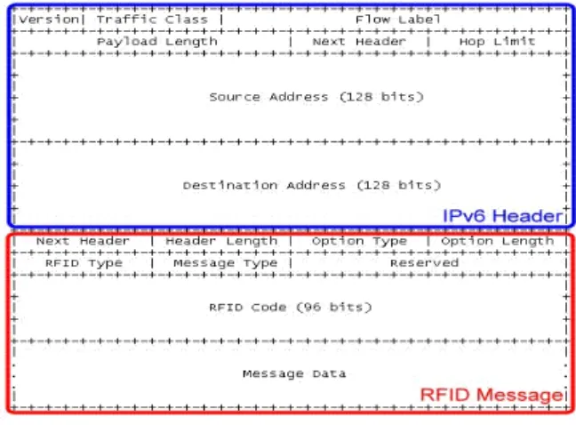
(4) Tracking System is considered to be a hierarchical architecture with well scalability and high efficiency. The message format is defined as Fig. 8.. analyzed in this section. The model of the proposed RFID Object Tracking System forms an architecture model, and it will be compared with other models for showing its high efficiency and well scalability.. 4.1 Bridge-based RFID System (BNet). Figure 8: General RFID Message Format The modification of RFID information is specified for at least one RFID code, and may be more than one. To process the modification for a group of RFID tags, multiple RFID codes in one message is considered as well. The RFID Code field in the general message format carries one RFID code. When information about more than one RFID code is to be modified, the second and following RFID codes will be carried in Message Data field. For reliable transmission, the RFID messages are carried within TCP payload. Figure 9 shows IPv6 RFID payload.. The system architecture of Integrated RFID Health Delivery Network has been shown in Figure 3, and its topology is shown as Figure 11. RFID Readers are linked to one bus which is called RFID Reader Network here. The database node, webserver node, and other existing information server nodes are connected together using another bus which is called System Network here. RFID messages to be delivered to System Network will be relayed by a bridge component. These nodes and connections form a Bridge-based Network Model. Triggered by RFID tags’ movement, RFID Readers generate messages at random. Those messages collected to the bridge component via the RFID Reader Network switch did not be reduced in packet amount, but just were translated to deliver from Reader Network to IP Network.. IPv6 TCP RFID Message Base Header Header Figure 9: IPv6 RFID TCP Payload Considering the IPv6 advantages, the RFID message may be carried in the flexible extension header instead of the payload for efficient information exchange at network layer. Figure 10 shows the concept of message format in extension header. Figure 11: Bridge-based RFID System. 4.2 Gateway-based RFID System (GNet). Figure 10: Message Format in IPv6 Extension Header. The system architecture of the RFID Location-Based Medicare Service has been shown in Fig. 4 and its topology is shown as Fig. 12. In topology similar to Bridge-based Network, RFID Gateway collects all messages from Reader but makes filtering procedures instead of transforming and relaying only. Furthermore, the protocol interworking with the information system could be built in the Gateway for more useful functions. Gateway-based Network significantly reduces the loading of the System Network and improves the performance of application system as well.. 4 RFID NETWORK MODELS. 4.3 Hierarchical RFID System (HNet). The well adaptability of RFID modules makes RFID systems to be a variety of structures. Reader and every kind of nodes in system compose diverse network model. After analyzing those network models, developers can choose the most suitable model for their objective applications. In Section 2 several RFID projects have been surveyed, and their network models will be. In the scenario of RFID Object Tracking System, RFID tags would travel a long range which needs numerous networks to cover. To link these networks to track the movement of RFID objects, LRC nodes are interworking with the GRC nodes. The RFID Gateway collects RFID messages from Reader Networks, filters an amount of messages and merges them into a few records, then communicates with LRC using the reduced. - 768 -.
(5) records. This hierarchical architecture maintains the system operation efficiently and provides a good scalability for extending the tracking system. Figure 13 shows the topology of the hierarchical RFID Object Tracking System.. TR1 = TR2 = TR3 = TR4 = exponential(x) ms (Variable) To approximate a reasonable comparison among three different models, the network modules settings were configured as the common values. The nodes performing similar functions in similar topological positions were configured with similar capacities.. 5.1 Average Delay from RFID Readers to DBS Figure 14 illustrates the different average delay trends of the three system models. With a low Reader Arrival Rate , BNet delivered messages with the shortest delay, while GNet took the most time. This is because GNet and HNet employed the gateway component consuming several service intervals to wait and merge messages into records. HNet distributes readers over the domains of gateways reducing the system loading as well as the required waiting interval to merge messages. Therefore, HNet has a shorter delay time than GNet.. Figure 12: Gateway-based RFID System. The delay values of BNet and GNet increased as the Reader Arrival Rate rose. BNet and GNet almost caused an overflow when Reader Arrival Rate obtained the value 1.67. HNet remained with reasonable situation, because the large number of RFID messages was divided into several subnets, each handled by their own gateways.. Figure 13: Hierarchical RFID Object Tracking System. 5 PERFORMANCE ANALYSIS The operating parameters of RFID network systems are listed in the following. y Cables in RFID Reader Network 10 Mbps capacity with propagation delay = 0 ms y Network Capacity of RFID Reader Switch 10 Mbps capacity with Service Waiting Time = exponential(0.143) ms/message y Network Capacity of Bridge 100 Mbps capacity with Service Waiting Time = exponential(0.014) ms/message y Cables in System Network 100 Mbps capacity with propagation delay = 0 ms y Network Capacity of System Network Switch 100 Mbps capacity with Service Waiting Time = exponential(0.014) ms/message y Server Network Capacity 100 Mbps capacity with Service Waiting Time = exponential(0.014) ms/message y DBS Message Merging Rate 0.2 record/message y Network Capacity of Connection to Internet 10 Mbps capacity with Service Waiting Time = exponential(0.143) ms/message y Message Arrival Waiting Time of RFID Readers 10 Mbps capacity with Message Arrival Waiting Time:. Figure 14: Message Delay from Readers to Database System. 5.2 System Network Loading The average job queuing in the central switch of RFID system network was adopted to evaluate the system network loading. Figure 15 shows the system network loading. BNet had the highest average loading, because the RFID messages were not filtered until they were received by the DBS. The gateway reduced the system network loading of GNet and HNet 41.8%. However, the necessary communication with GRC makes the average system network loading in HNet higher than in GNet.. 5.3 Database System Loading The average job queuing in the main database system of RFID application system is utilized to evaluate the. - 769 -.
(6) DBS loading. Figure 16 shows the database system loading. The database system loading of BNet is sensitive to the arrival rate of RFID messages without message filtering. The database systems in GNet and HNet work stably in spite of the rising arrival rate of RFID message. However, the hierarchical architecture makes the DBSs in HNet share out their system loading. That is why the average DBS loading in HNet is so small under the one in GNet (about 83.2%).. Figure 15: System Network Loading in Three Models. Figure 16: Database System Loading in Three Models. 6 CONCLUSIONS This study introduced the RFID principles as well as its application system, surveyed the EPCglobal system, considered the integration of RFID system and IP technology, designed an RFID object tracking system as well as its network architecture, operating protocol and message formats and evaluated the operating performance in three RFID network systems by analysis and simulation. The research results show that the proposed hierarchical RFID object tracking system is good at scalability with high-efficiency; the gateway-based RFID system is suitable for applications within localized network; and bridge-based RFID system is a lightweight solution for small scale RFID systems.. 7 ACKNOWLEDGMENTS This paper is a partial result of project no. NSC94-2219-E-259-003 conducted by National Dong Hwa University under the sponsorship of the National Science Council, ROC.. REFERENCES [1] R.A. Kleist, T.A. Chapman, D.A. Sakai and B.S. Jarvis, RFID Labeling, Printronix, CA, 2004. [2] R. Weinstein, “RFID: A Technical Overview and Its Application to the Enterprise,” Proceedings of IEEE IT, pp.27-33, May-June, 2005. [3] R. Want, “RFID: A Key to Automating Everything,” Scientific American, pp.56-65, January 2004. [4] D.M. Ward, “RFID Systems,” Computer in Libraries, pp.19-24, March 2004. [5] K. Finkenzeller, RFID Handbook, Wiley, Second Edition, 2003. [6] J. Riekki, T. Salminen and I. Alakarppa, “Requesting Pervasive Services by Touching RFID Tags,” IEEE Pervasive Computing, Vol.5, No.1, pp.40-46, Jan.-March 2006. [7] P. Repo, M. Kerttula, M. Salmela and H. Huomo, “Virtual Product Design Case Study: The Nokia RFID Tag Reader,” IEEE Pervasive Computing, Vol.4, No.4, pp.95-99, Oct.-Dec. 2005. [8] C. Legner and F. Thiesse, “RFID-Based Maintenance at Frankfurt Airport,” IEEE Pervasive Computing, Vol.5, No.1, pp.34-39, Jan.-Mar. 2006. [9] EPCglobal Inc. Home Page, http://www.epcglobalinc.org [10] B. Nath, F. Reynolds and R. Want, “RFID Technology and Applications,” IEEE Pervasive Computing, Vol.5, No.1, pp.22-24, Jan.-Mar. 2006. [11] J. Landt, “The History of RFID,” IEEE Potentials, Vol.24, No.4, pp.8-11, Oct.-Nov. 2005. [12] R. Want, “An Introduction to RFID Technology,” IEEE Pervasive Computing, Vol.5, No.1, pp.25-33, Jan.-Mar. 2006. [13] Gautam, “Act Sober with RFID World Cup Tickets,” The RFID Weblog, Jun. 2006. [14] J.G. Lee, S.J. Hwang, S.W. Kim, S. Ahn, K.H. Park, J.H. Koo and W.S. Kang, “Software Architecture for a Multi-protocol RFID Reader on Mobile Devices,” Proceedings of the International Conference on Embedded Software and Systems, pp.8, Dec. 2005. [15]C.J. Li, “An Integrated Software Platform for RFID-Enabled Application Development,” Proceedings of the IEEE International Conference on Sensor Networks, Ubiquitous, and Trustworthy Computing, Vol.1, pp.332-335, Jun. 2006. [16] J. Lee and N. Kim, “Performance Test Tool for RFID Middleware: Parameters, Design, Implementation, and Features,” Proceedings of the International Conference Advanced Communication Technology, Vol.1, pp.149-152, Feb. 2006. [17] Auto-ID Labs, http://www.autoidlabs.org [18] R.S. Sangwan, R.G. Qiu and D. Jessen, “Using RFID Tags for Tracking Patients, Charts and Medical Equipment within an Integrated Health Delivery Network,” Proceedings of the IEEE Networking, Sensing and Control Conference, pp.1070-1074, Mar. 2005. [19] S.W. Wang, W.H. Chen, C.S. Ong, L. Liu and Y.W. Chuang, “RFID Application in Hospitals: A Case Study on a Demonstration RFID Project in a Taiwan Hospital,” Proceedings of the Annual Hawaii International Conference on System Sciences, Vol.8, pp.184a, Jan. 2006.. - 770 -.
(7)
數據
+3


相關文件
(2) 被動式 RFID Tag(Passive):被動式 RFID Tag 不含電池,其能量是 感應自 RFID Reader 所發射過來的 RF 無線電波能量,當 RFID
Choi, “A Hybrid Query Tree Protocol for Tag Collision Arbitration in RFID systems”, IEEE International Conference on Communications (ICC-07), pp.24–28, 2007. Cole, “THE
Keywords: RFID, Mobile Learning, Sequence knowledge, Bloom’s cognition taxonomy, Ubiquitous Context-Aware. Distance learning has impacted and transformed conventional
Besides, we also classify the existing RFID protection mechanisms to solve the different personal privacy threats in our security threat model.. The flowchart of security threat
Through the help of this study, the inconvenient of insufficient information of biological pilot plant can be improved, the manufacture security can be promoted, and the
This study will use BIM, Web-base, RFID, Wireless Network, ER Model, Database and Information Technology environment to develop “Electronic Building Construction
With the advancement in information technology and personal digital mobile device upgrade, RFID technology is also increasingly common use of the situation, but for
在 EPC Radio-Frequency Identity Protocols Class-1 Generation-2 UHF RFID Protocol for Communications at 860MHz-960MHz Version 1.09 的規範之下,我們選定的 RFID
