國
立
交
通
大
學
網路工程研究所
碩
士
論
文
真實網路系統設計與實作的問題分析與解決方案
Design and Implementation of a real networking system:
Problem taxonomy and solutions
真實網路系統設計與實作的問題分析與解決方案
Design and Implementation of a real networking system:
Problem taxonomy and solutions
研 究 生:李奕萱 Student:Yi-Shuan Lee
指導教授:曾建超 Advisor:Chien-Chao Tseng
國 立 交 通 大 學
網 路 工 程 研 究 所
碩 士 論 文
A ThesisSubmitted to Institute of Network Engineering College of Computer Science
National Chiao Tung University in partial Fulfillment of the Requirements
for the Degree of Master
in
Computer Science
June 2010
Hsinchu, Taiwan, Republic of China
Design and Implementation of a real networking system: P r o b l e m t a x o n o m y a n d s o l u t i o n s Student: Yi-Shuan Lee Advisor: Dr. Chien-Chao Tseng
Institute of Network Engineering College of Computer Science National Chiao Tung University
Abstract
Although many references on programming techniques exist on Internet, they are not organized systematically. Therefore, programmers normally have to spend a lot of time searching for solutions when they encounter problems during the development of a real system. Therefore, this thesis aims to present some programming or development techniques that can help programmers to identify and resolve the
system and then provide the solutions to these problems.
Our discussion includes the behavior of servers, the interaction of clients and servers, the resource management, the error tolerance and the exception handling of components. These discussions and experiences are not only helpful to programmers of BRIC-like applications, but also are beneficial to developers of other kinds of applications.
真 實 網 路 系 統 設 計 與 實 作 的 問 題 分 析 與 解 決 方 案
研究生: 李奕萱 指導教授: 曾建超 教授
國立交通大學網路工程研究所
中文摘要
程式設計者在開發系統或專案時,經常遇到實作上的難題,但是探討實作 問題的論文或參考資料並不多,導致程式設計者常常需要花費很多的時間和心力 去搜尋相關的資料來得到解決方法。因此,本篇論文提供了這方面的參考資料, 希望可以對程式設計者有所幫助。本篇論文根據我們開發系統以及在真實網路環 境中使用該系統的經驗,整理出在實作以及實際應用過程中所遇到的問題,進而 討論這些問題是如何影響到一個系統的效能或運作狀況,並且提出這些問題的解 決方法。 本篇論文以一個網際網路常見的應用—遠端 IP Cam 瀏覽(Browsing Remote IP Cam; BRIC)為範例,介紹的開發此系統時該注意的實作問題與解決 方法。從大方向來看,本篇論文探討的問題大致包含系統裡伺服器的行為、客戶的程式設計者許多幫助之外,其中的許多觀念針對各種程式設計或是系統開發的 情況都是適用並且值得參考的。
誌謝
終於可以寫誌謝了!這是我期待已久的一刻,因為這代表了我終於完成了研 究所的學業以及碩士論文,當然這是我一個人無法獨立做到的,因此就以這篇誌 謝來好好感謝和我一起走過這段求學路程的每一個人。 第一份最大的感謝,當然要獻給從小到大一直在我身邊的家人。包括了總是 照顧著我愛護著我,並且相當用心栽培我的爸媽、在求學路上一直是我的表率的 哥哥、遠在花蓮卻還是時常關心著我的學業和生活的舅舅,以及我的公公 – 我 們全家人最尊敬的長者,即使您提早一步蒙主寵召,來不及看到我和哥哥畢業, 但每當想到您時總還是會讓我充滿力量。謝謝家人們一直以來對我的包容與關 愛,我愛你們! 接著要感謝我的指導教授 – 曾建超教授。兩年前我的成績和學術上的表現 並不算優異,謝謝您不嫌棄的收了我進實驗室,給了我學習的機會,也謝謝您在 我有進步時大力肯定我的表現,讓我知道努力不會白費。此外,也謝謝擔任我的 口試委員的王讚彬教授,曹孝櫟教授以及張弘鑫教授,因為有你們的指導與建 議,讓這篇論文能夠更加完善。 在研究所的生活中,實驗室就像是一個大家庭一樣,帶給我在學校所需要的 一切依靠和溫暖。謝謝小布、良哥、俊延、媛莉、興謙、又仁、承運、姿欣以及 Gunter 等學長姐在碩一這一年來給予我們的照顧和幫助;也謝謝在我們升上碩 二時為實驗室再度帶來活力的學弟妹們 – 明辰,家明,沅春,阿彪,圈圈以及 和我最要好的貞慧,未來一年換你們好好加油!當然也要感謝兩年來最要好的夥 伴 – 昱樺、宗鴻、竣晨、銘祥和坤穎。和你們一起修課一起準備考試,假日一 起待在學校看球賽寫程式趕作業的這些日子真的是苦中帶甜,笑中帶淚!兩年來 我們總是很團結的互相幫助與合作,因此不管是課業還是論文的挑戰,我們都算 是蠻順利的通過了。謝謝你們總是無私的分享所學,也讓我的研究所生活充滿了 歡笑!堯,Vincent,東寰,阿毓,Harry 和 Artist,很高興可以和你們共事,一起學習 一起成長。也謝謝同時身兼我工作上的主管、論文指導者且亦師亦友的承遠,你 的功績如果要一一列出的話,可能要花一整章來寫才足夠了(笑),僅以"沒有你 就沒有這篇論文"來表示你對我們的重大影響與幫助,衷心希望你未來的工作生 涯會越來越順遂! 說完正經的,接下來來點輕鬆的!再怎麼認真做研究也還是要填飽肚子,謝 謝有茶氏老闆和金城老闆,這兩家店是我出外生活的最愛,好吃的菜餚和好喝的 飲料總是讓人感到滿足,再加上老闆的熱情招呼就更加親切了☺ 謝謝一支我從 小到大都支持的球隊 – 兄弟象,即使發生了這麼多風風雨雨,你們仍舊秉持著 永不放棄的精神繼續前進,這股信念也是在我遇到難關時總會支持我撐下去的動 力!謝謝崔西希克曼和瑪格麗特魏斯,你們兩人著作的"龍槍"系列小說豐富了 我暗無天日的趕論文生活,是不可或缺的精神糧食。當然,也要謝謝大學時期認 識的眾多好朋友們,尤其是我最要好的姐妹維妮、蜜祐和筱華,以前是好夥伴以 後還要繼續當同事的裕翔,以及常常和我聊天紓解壓力,也給予我很多學術上的 協助和建議的小武。友情總是會讓人充滿能量,很高興能夠一直有著好朋友的祝 福和鼓勵陪伴我一路走來。 在這篇誌謝的尾聲,要獻上最後一份大大的感謝給我的男朋友鼎力。在學術 上,因為你早我一年,讓我得以獲得很多你的經驗,你對資訊領域的熱情也漸漸 感染了我,讓我對我們的所學更加有熱忱;在生活上,你總是可以在我沮喪的時 候讓我開心,在我開心的時候陪著我分享,在我努力朝目標邁進的時候給予我全 力的支持和幫助。謝謝你出現在我的生命中,也謝謝以上所提及的每一位,沒有 你們我就無法擁有如此充實又多采多姿的這兩年,這將會是我人生中最美好的回 憶 ☺
CONTENTS
Abstract...ii 中文摘要 ...iv 誌謝...vi CONTENTS... viii LIST OF FIGURES ...xLIST OF TABLES ...xii
Chapter 1 Introduction...1 Chapter 2 Background ...2 2.1. NAT...2 2.1.1. NAT Mapping ...2 2.1.2. NAT Filtering ...6 2.1.3. NAT traversal ...9 2.2. Fairness measure...10
Chapter 3 System Architecture...13
3.1. System Design Purpose...13
3.2. An Example ...14
3.2.1. Architecture...15
3.2.2. Component Overview ...18
Chapter 4 Development problems ...22
4.1. OS related problems...22
4.1.1. Limited connection pair ...22
4.1.2. Unfair Resource Sharing...28
LIST OF FIGURES
Figure 2-1 NAT mapping table...3
Figure 2-2 Independent mapping ...4
Figure 2-3 Address dependent mapping ...5
Figure 2-4 Address and port dependent mapping ...5
Figure 2-5 Independent filtering ...7
Figure 2-6 Address dependent mapping ...8
Figure 2-7 Address and port dependent mapping ...9
Figure 3-1 System scenario...14
Figure 3-2 Architecture of BRIC ...16
Figure 3-3 Steps of connection setup...17
Figure 3-4 Steps of streaming data transmission ...19
Figure 3-5 Relay ...21
Figure 4-1 Function declaration of select()...23
Figure 4-2 Adding fd 3, 4, 5, 7, 8, 9 in the fd_set...24
Figure 4-3 fd_set array with fixed size 1024 ...24
Figure 4-4 Scenario of unfair resource sharing...29
Figure 4-5 FIFO method – normal case...30
Figure 4-12 Output messages when new threads are created ...37
Figure 4-13 Function declaration of pthread_create() ...38
Figure 4-14 An example code of pthread_create() ...39
Figure 4-15 One location per connection...40
Figure 4-16 Critical section ...41
Figure 4-17 Session interference ...43
Figure 4-18 Incorrect packet alignment...45
Figure 4-19 Solution to incorrect packet alignment ...46
Figure 4-20 Example code of setsockopt() ...47
Figure 4-21 Real time announce by Relay Server ...49
LIST OF TABLES
Table 4-1 Comparison of two methods...42 Table 5-1 Improvements after modification ...51
Chapter 1 Introduction
There are few related articles and books about developing a real system, so programmers have to spend a lot of time to search for
solutions when they encounter problems. Therefore, we want to provide a reference for building a real system, decrease people’s searching time so that they can focus on implementation.
We can find many papers that discuss the topic of system design or system architecture, but some of them just focus on one component, which is too narrow [1]; others just discuss the architecture of a system but don’t describe the detail of components and implementations [2]. This article includes both of them, from architecture design to component design and interaction between components. Based on our experience of developing a system and using the product in real life, we summarize the problems we faced, and discuss how they affect a system and provide their solutions.
Chapter 2 Background
2.1. NAT
Network Address Translation (NAT) [3, 4, 5, 6] is a mechanism where a device performs translations to the address and port number of a
packet. NAT alleviates the IPv4 address exhausting problem by mapping multiple private IP addresses to one public IP address, so hosts on a private network can access the Internet using the public IP address allocated by the NAT. In the following, we first introduce two primary functions of an NAT – mapping and filtering [7]; then we state the NAT traversal problem and list some existing solutions to it.
2.1.1. NAT Mapping
The NAT mapping is required to maintain a session between the internal network and the external network of a NAT. When an internal host
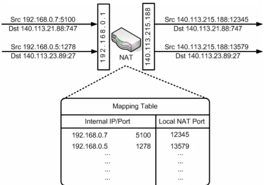
Figure 2-1 NAT mapping table
A NAT maintains a mapping table (also called masquerading table) which records several [internal IP: port] and [external IP: port] tuple entries such as Figure 2-1. According to the mapping table, the NAT is able to translate the [internal IP: port] in a packet header to an [external IP: port] for routing outside the NAT. NAT mapping behaviors can be classified into three categories:
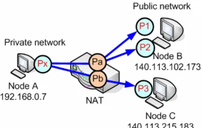
Independent: The sessions start from the same [internal IP: port] are mapped to the same [external IP: port], although their
destinations are different. For example, in Figure 2-2, no matter the internal host, node A, sends packets to the different ports P1, P2 on node B or P3 on node C, NAT would assign the same
[external IP: port] (Pa) to those sessions.
Figure 2-2 Independent mapping
Address dependent: The sessions from the same [internal IP: port] to the same destination host are mapped to the same [external IP: port], regardless of the port number on the destination host. For example, Figure 2-3 shows that NAT would assign (Pa) when node A sends packets to P1 and P2 on node B, but when the destination is node C, the NAT assigns (Pb) to the session.
Figure 2-3 Address dependent mapping
Address and port dependent: Only the sessions from the same [internal IP: port] to the same destination IP address and port number are mapped to the same [external IP: port]. As shown in Figure 2-4 , if the destination IP addresses or ports are different, NAT would assign different [external IP: port].
Figure 2-4 Address and port dependent mapping
2.1.2. NAT Filtering
When an internal host opens an outgoing session through a NAT, the NAT assigns a filtering rule for the session. The filtering rule means what criteria are used by the NAT to filter packets originating from external hosts, in other words, according to the filtering rule, the NAT decides what packets can pass and forwards them to the internal host; on the contrary, the packets that don’t meet the rule are dropped by the NAT. The same as above, the NAT filtering behaviors can also be classified into three categories:
Independent: Internal hosts behind the NAT send packets to any external IP address is sufficient to allow any packets from external host with any IP address and port back to the internal host. As shown in Figure 2-5, once node A sends packets through the NAT, any inbound packets from external hosts such as P1, P2 and P3 can pass the NAT and be received by node A.
Figure 2-5 Independent filtering
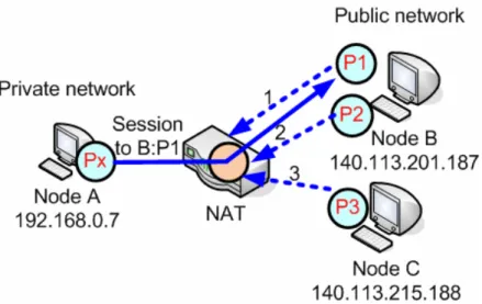
Address dependent: In order to receive packets from a specific external endpoint, it is necessary for the internal endpoint to send packets first to that specific external endpoint's IP address. For example, Figure 2-6 shows that once the session has been
established between node A to node B, only inbound packets from external host, node B, such as P1 and P2 can pass through the NAT. Packets from node C, on the other hand, are dropped by the NAT.
Figure 2-6 Address dependent mapping
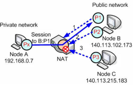
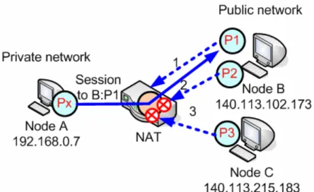
Address and port dependent: This behavior is similar to the previous one, but it’s stricter because the external port is also relevant. If internal hosts want to receive packets from a specific external host, it is necessary for them to send packets first to that specific external host's IP address and port. For example, in Figure 2-7, once the session has been established between node A and (P1) of node B, only inbound packets from P1 can pass the NAT. Packets from (P2) of node B and (P3) of node C are all dropped by
Figure 2-7 Address and port dependent mapping
2.1.3. NAT traversal
As described before, an external node which locates outside the NAT can send packets to an internal node only because the internal node sends out packets first. Consequently, an external node cannot initial communication to an internal node behind the NAT. This is widely known as the NAT traversal problem. Although using IPv6 technology, which does not need NATs, is the long term solution to the IPv4 address
exhausting problem, the technology has not spread to home network yet. So, the NAT traversal technologies are still important and the demand for it is increasing.
three types [8]:
NAT Behavior-based type: This type of NAT traversal approaches can use regular NATs without modification; the goal of NAT traversal is achieved by modifying the applications. This type of approaches is mostly used in the real life such as STUN [9], TURN [10] and ICE [11].
NAT Control-based type: This type of approaches creates NAT mapping by adding functions to a NAT device, so programmers need to have the permission to do modifications on the device. An example to NAT Control-based approach is UPnP IGD [12].
NAT-less type: This type of approaches, such as IP 4+4 [13], solves the problem by its own process without the NAT. Approaches of this type are considered less practical and hard to implement in real life because they may need to modify the protocol stack.
Jain’s equation,
(
)
(
∑
⋅
∑
)
=
2 2 i ix
n
x
fairness
rates the fairness of a set of values where there are n users and xi is the
throughput for the ith connection. The result ranges from
n
1 (worst case) to 1 (best case), and it is maximum when all users receive the same
allocation. This index is
n
k when k users equally share the resource and the other n - k users receive zero allocation.
Above is the mathematical explanation of Jain’s fairness. After that, we use an example to describe it in vernacular. Assume there are ten bowls of rice and five people who want to share them, the fairest way to share the bowls in Jain’s fairness index is everyone gets two bowls, in spite of their different appetite. That is to say, in Jain’s fairness index, “fairness” means everyone has equal opportunity to access resources no matter what their own demands are.
2. Max-min fairness [16]
In Max-min fairness, resources are distributed to everyone according to their demand. Continue using the above example, assume the five people who want to share the rice are composed of two boys, one girl
and two children, so the fairest way to share the bowls in Max-min
fairness may be three bowls for boys, two bowls for girl and one bowl for the children. Unlike the unconditional equality in Jain’s fairness,
Chapter 3 System Architecture
3.1. System Design Purpose
We want to build a system that supports users watch remote image through the web browser, which is very simple and convenient.
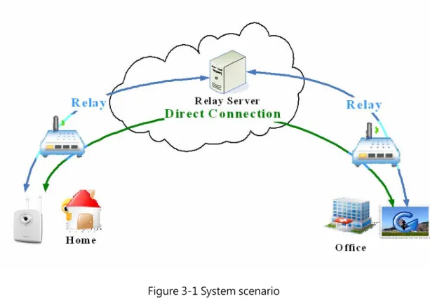
Take Figure 3-1 for example, the left part represents a room, a house or any place that have things users care about, so they put an IP camera in there. The right part can be an office or a school. Parents may want to see whether their children are safe at home while they are
working, or students may miss their pets when they are at school. At this time, all they have to do is get on the Internet and open the web browser, than they can see what they want to see.
Figure 3-1 System scenario
The place of the IP camera may be far from the user’s office or school, and both places are likely to be under some complicate network environment, for example, multiple NATs. This kind of system provides NAT traversal mechanism for building direct connections through NATs. If the direct connection can’t be build successfully, there is a Relay server to help both sides deliver packets. Above mechanisms are used to make sure users can watch images they are interested in no matter where the
introduce this kind of system. The system we developed is called Browsing Remote IP Cam (BRIC), we describe the system architecture and make an overview of components in BRIC.
3.2.1. Architecture
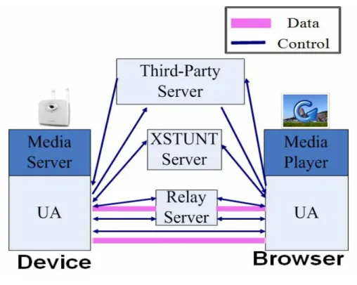
Figure 3-2 is the architecture of BRIC system. There is an IP camera on the left side of the figure, the IP camera contains two components: a user agent (UA) that we implemented and a media server which provides media streaming. On the right side there is a web browser, there are also two components in the web browser: an UA and a media player that can play the media streaming on the browser. For simplicity, we use the word “Device” to represent the IP camera side and “Browser” to represent the web browser side in the following article. On the top of the figure there is a third-party server which keeps the location of every active device. Between the device and the browser, there are two servers: an XSTUNT server and a Relay server, both servers provide help for connection setup between a device and a browser.
Figure 3-2 Architecture of BRIC
We first describe the steps of connection setup to show the general idea of the system and the role of each component in the system. Then we introduce each component more detailed.
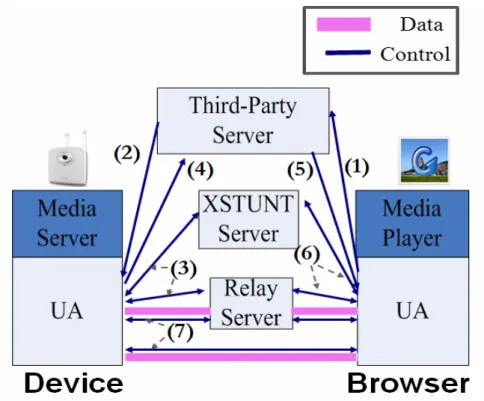
Figure 3-3 Steps of connection setup
Figure 3-3 shows the steps of connection setup.
Step1. When a user connects to the portal site of the system and clicks the icon of a specific device, it means the user wants to watch image of this IP camera. A message is sent by the portal to the third-party server to ask it to find the device.
Step2. The third-party server finds the specific device and notifies it that someone wants to build a connection with it.
Step3. The device registers at the XSTUNT server and the Relay server after it is notified by the third-party server.
that it is ready.
Step5. The third-party server then tells the browser that the device is ready.
Step6. The browser registers at the XSTUNT server and the Relay server.
Step7. After above six steps of message exchanging, the device and browser start trying to build a direct connection through the help of
XSTUNT server. The Relay server is used if the direct connection path can’t be built.
3.2.2. Component Overview
In this section, we make an overview to the components in BRIC system. We only focus on the three components we developed, so the media server, media player and the third-party server are beyond the scope of this discussion.
connections to pass through NATs. As describe before, according to different network environments, there are direct connection paths and relay paths.
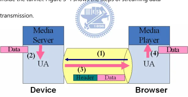
Second kind of functions is to help users to watch remote image on browsers. These functions work after the connection is built, which means the path for data transmission is decided, no matter it is a direct
connection path or a relay path. The path is considered as a tunnel, control message and data are encapsulated by a UA header and flow inside the tunnel. Figure 3-4 shows the steps of streaming data
transmission.
Figure 3-4 Steps of streaming data transmission
Step1. The browser UA sends a command to device to ask for media streaming
server
Step3. The device UA sends the media streaming to the browser UA Step4. The browser UA passes the media streaming to the media player, so the user can watch it.
XSTUNT
XSTUNT [17] is an open source, and we made some adjustments to make it suitable for our system.
XSTUNT is an extension to STUNT [18]; it implements partial functions of STUNT, so we talk about STUNT before introducing XSTUNT.
STUNT is an abbreviation of “Simple Traversal of UDP through NATs (STUN) and TCP too”. STUN [9] is an NAT traversal method for UDP, and STUNT extends STUN to include TCP functionality, which allows
applications running behind NATs to obtain their external IP and port-binding properties, packet filtering rules and various timeouts associated with TCP connections through the NAT.
XSTUNT helps hosts behind NATs to establish a TCP direct connection.
Relay
The device and the browser are relay clients, and the Relay server forwards data from one side to the other side. As Figure 3-5 shows, the device and the browser each build a connection with the Relay server, and they can send data to each other through the Relay server. The Relay server ensures every user can connect to their device to watch image, so it is the last line of establishing connections.
Chapter 4 Development problems
According to their caused, problems we encountered in developing a system can be classified into two categories, which are OS related
problems and programming problems. OS related problems are caused by the behavior of OS, and programming problems has nothing to do with the OS, they happen because of there’s some mistakes or
negligence in writing the program. In the following, we introduce the two kinds of problems.
4.1. OS related problems
4.1.1.
Limited connection pair
Every server has an approximate upper bound of number of clients it can serve. Here we observe a problem that a server can’t serve new clients while number of clients currently served is still far from the upper bound. In the following we will describe two possible causes of this
23].
In the beginning, we introduce the select() system call. UNIX
applications use select() to monitor multiple fds to see whether they are “ready” or not. An fd is considered “ready” if it is possible to perform some I/O operation (e.g., read, write) without blocking. Figure 4-1 is the declaration of select(). The nfds is the largest fd number actually used; the
timeout controls how long the select() will return if no fds become ready;
fds are added into an fd_set for select() to monitor, there are readfds,
writefds and exceptfds for reading, writing and exception events
respectively. The fd_set can be regarded as an array, if we add an fd into it, the entry corresponding to the fd number is marked. One fd is mapped to one specific location in fd_set. Figure 4-2 is an example of adding fd 3, 4, 5, 7, 8, 9 into the fd_set.
Figure 4-1 Function declaration of select() #include <sys/select.h>
int
select(int nfds, fd_set *readfds, fd_set *writefds, fd_set *exceptfds, struct timeval *timeout);
Figure 4-2 Adding fd 3, 4, 5, 7, 8, 9 in the fd_set
Next, we talk about the limitation caused by OS. The fd_set has a fixed size 1024 decided by the OS, so the index of the array starts from 0 to 1023. That is to say, the maximum fd number that can be added into the fd_set is 1023 (Figure 4-3). Buffer overflow will happen if we add an fd larger than 1023 into the fd_set, and it may bring about some potential problems on the program. Note that it is not the amount of fds but the fd number that is restricted by the OS limitation, and the OS assigns fd number incrementally. Take our system for example, a pair of clients build three connections with the Relay server, so there are only 341 (1024/3) pair of clients can be simultaneously served, which is not good enough for a server that used by a lot of people.
Solution 1. Modify and re-compile the kernel to change the size of fd_set
Following are the modifications made in our BRIC system
/usr/include/bits/typesizes.h:63: define __FD_SETSIZE 4096 /usr/include/linux/posix_types.h:25: define __FD_SETSIZE 4096 /usr/src/redhat/BUILD/kernel-2.6.23/linux-2.6.23.i686/include/linux/posix_types.h:25: define __FD_SETSIZE 4096 sysctl -w net.core.rmem_max=8388608 sysctl -w net.core.wmem_max=8388608 sysctl -w net.ipv4.tcp_moderate_rcvbuf=1 sysctl -w net.ipv4.tcp_rmem="32768 87380 8388608" sysctl -w net.ipv4.tcp_wmem="16384 65536 8388608" sysctl -w net.ipv4.tcp_mem="8388608 8388608 8388608" sysctl -w net.ipv4.tcp_syncookies=0 ulimit -n 65535 ulimit -s unlimited ulimit -u unlimited
Solution 2. Replace select() by epoll()
epoll() [24, 25] is a new system call introduced in Linux 2.6. Unlike
select(), which is O(n), epoll() is an O(1) algorithm -- this means that it
scales well as the number of watched fds increase. epoll() has no limitation on the amount of fds or the fd number, it can support fds as
much as the max open files supported by OS, which is much more than 1024. This value could differ from system to system, for example, the value is 203800 on the Linux server in NCTU.
Followings are the comparisons of the two solutions; programmers can choose one of them according to their circumstances and
requirements. There’s no need for programmers to rewrite their code if solution 1 is used, they just have to modify and recompile the kernel to enlarge the limit value. But programmers may not have the permission to make the changes on the machine they are using, so this solution is not suitable for every circumstance. Moreover, it takes extra time to recompile kernels. On the other hand, solution 2 is a long-term solution for this problem, because epoll() is proposed exactly for replacing select(). The problem is that epoll() is a new system call that people are less familiar with it comparing with select(), therefore, programmers have to spend more efforts on learning how to use it and adjusting their original code.
can be joinable or detached. This attribute determines whether another thread may wait for the termination of the thread or not. A thread can be terminated by calling pthread_exit(), but pthread_exit() doesn’t handle the resource clean up of the thread. If a joinable thread terminates, resources used by it are not freed until another thread called
pthread_join(). pthread_join() suspends the calling thread, waits for the
termination of a specific joinable thread, and releases the resources used by it. That is, the resources used by a joinable thread are cleaned up by another thread who calls pthread_join(). On the other hand, when a
detached thread terminates, the resources used by it will be automatically reclaimed. Because a detached thread has no relationship with other threads, so there’s no need for another thread to clean up resources for it.
The default value of “detach state” of a thread is joinable, which means a thread is set to joinable if there’s no extra change to it after its creation. In the situation that a server creates many joinable threads without calling pthread_join() in other threads to wait for their
termination, the system resources will be exhausted soon, even if those threads are all terminated, because a joinable thread doesn’t release
resources by itself on termination. As a result, the server may not accept new clients after running a short time.
Through the example above, we can see that it is very important to do the resource clean up for a joinable thread by calling pthread_join() in another thread. But in our BRIC system, a thread is created to serve a connection, and it has nothing to do with the parent thread, so it should be a detached thread. A thread can be set to detached by calling
pthread_detach() after it is created, thus the relationship with its parent
thread is cut off. In this case, no extra resource clean up process is needed. Programmers have to decide the “detach state” of a thread according to different scenarios, and handle the resource clean up appropriately.
4.1.2.
Unfair Resource Sharing
In a multi-thread program, process resources are shared by threads it created, but the resource may not be distributed to those threads in a fair way. One common case is that many threads compete with each other for
Figure 4-4 Scenario of unfair resource sharing
Take the situation in BRIC for example, two threads on device side are competing, the thread that gets the mutex can do what they want, and the other thread should wait. We can look at Figure 4-4, one thread is in charge of forwarding media streaming of the IP camera, and the other thread forwards the command of user to the camera, such commands can be zoom in, zoom out or rotate the camera lens. We use “streaming thread” and “command thread” to represent the two threads. The problem we encountered is that the streaming thread always gets the mutex, and the command thread can’t process the user command. Therefore, even the user keep clicking icons on the web portal to send
commands to the camera, the camera may have no reaction or react after a long while. Such unfair resource sharing may bring about bad user experience, so a fair resource sharing policy is needed.
Our solution is called FIFO method, and it is based on the idea of Max-min fairness. The FIFO method doesn’t force every thread to have the equal chance of earning the mutex, but it ensures every thread can do its job as long as it needs.
Figure 4-5 FIFO method – normal case
Figure 4-5 shows the FIFO method. As soon as a thread is willing to enter the critical section, its thread ID is recorded in an array maintained by the process, so the request order is also recorded in the array. In Figure
indicator, it can enter the critical section. Figure 4-5 shows this kind of situation. After thread A finishes its job and releases the mutex, the indicator then moves to the next field to point to thread B, representing that thread B has the right to enter critical section now. This is a normal case of threads competing the mutex. On the other hand, if thread B has better efficiency than thread A and gets the mutex before thread A, like Figure 4-6 shows, FIFO method won’t let thread B enter the critical section because the indicator doesn’t point to its thread ID now. The indicator won’t shift to the next field before the current thread releasing the mutex, so thread B has to wait until thread A finishes its job.
Figure 4-6 FIFO method – B runs faster than A
With the FIFO method, there’s no preemption to or from other threads, according to the request order, every thread can enter the critical section as long as it needs. Therefore, even a thread earns the mutex very
often, it won’t block other threads from doing their jobs. So, this is a fairer way of resource sharing.
4.2. Programming Problems
4.2.1.
Imprecise relay path confirmation
In order to avoid losing of important data, we need to check whether a path is ready or not before we start to send data on that path.
First we discuss the simplest situation, the path confirmation between only two nodes. The confirmation is initiated by one of the two nodes by sending a test string to the other node. Take Figure 4-7 for example, node A is the initiated node, and node B returns what it receives from node A back to node A. The path will be considered ready if node A receives the same test string returned from node B.
path is more necessary to be confirmed in advance, because each peer build a connection with the Relay server respectively, they have no idea about whether the counter part is ready or not. The above idea is very simple and intuitive, but if we use the same idea in the relay situation, the path confirmation will become imprecise, which means a successful case may be misjudged to be a failed case. As mentioned before, relay is the last line of establishing connections, using an imprecise confirmation method is harmful to the system, because it lowers the connection rate.
Figure 4-8 End Device Initiated Confirmation
We use Figure 4-8 to explain why using above idea in the relay case is imprecise. We call this method End Device Initiated Confirmation. A Relay server locates between the device and the browser. In data transmission, the browser will send the first message to ask the device for media
streaming, so the relay path confirmation should initiated by the browser. After the browser is connected to the Relay server, it sends a test string to the device through the Relay server and waits for the return from the device. This method is based on an assumption that when the initiated node sends the test string, the counter part is already connected to the Relay server. The assumption is usually true in the normal case, but there may be exceptions as Figure 4-9.
Figure 4-9 Exception situation in Relay path confirmation
which is short enough to be tolerant. If we don’t do the confirmation such eagerly, the relay path will be a successful case.
Our suggestion is that if relay is used in a system, the path confirmation should be done by the Relay server, we call it Server Controlled Confirmation. Because the Relay server can see both clients and knows about the connection status of them, it can make sure the device and the browser are connected before the path confirmation.
Figure 4-10 Server Controlled Confirmation
Figure 4-10 shows how the Server Controlled Confirmation works. Step1. After the device and the browser both connect to the Relay server, Relay server then sends an “OK” message to device.
Step2. The device returns an “AOK” message, representing the path between device and Relay server is ready.
after the device is ready.
Step4. The browser returns an “AOK” message, representing the path between browser and Relay server is also ready.
After above four steps are done and each message is received successfully, the relay path is judged to be ready for data transmission. Using this method, there will be no misjudgment in the situation
described before.
4.2.2.
Connection binding error
In network programming, a connection is represented by a file descriptor (fd). The problem we discuss here is that one file descriptor is used by multiple connections, this problem may happen when a lot of clients connect to a server in a very short duration (e.g., 10 clients in 1 second). If many connections are using the same fd, the server will become confused and can’t serve any of them.
new accepted connection is served by the thread. Figure 4-12 shows the output messages after the thread is created. Surprisingly, we found that all fds passed into the thread turn into 300!
Figure 4-11 Output messages when server accepts new connections
Figure 4-12 Output messages when new threads are created
function [20]. First we make a brief introduction to pthread_create(). Figure 4-13 is the function declaration of pthread_create(), this function is used to create a new thread within a process. The thread is created to execute start_routine with arg as its sole argument. That is, after the thread is created, it starts from the function start_routine(), and the arg is passed into start_routine() as its argument. Note that the arg must be passed by reference by casting its type to void*, no matter what type it was originally. If there are several arguments we want to pass into the thread, we can pack those arguments in a structure then pass the address of the structure.
Figure 4-13 Function declaration of pthread_create()
Now we explain why the connection binding error happens. Figure #include <pthread.h>
int pthread_create(pthread_t *thread, const pthread_attr_t *attr, void *(*start_routine)(void *), void *arg);
We use the address of the conn_fd as the last argument of
pthread_create(), after the thread is created completely, it copies the
value of conn_fd from arg and stores in a local variable of its own. The
pthread_create() takes time to create a new thread, it may not finish
immediately. So if the connections come very closely, the conn_fd of newly accepted connection is likely to overwrite the former conn_fds
before they are copied by the threads, because all the conn_fds are the same variable, using the same address.
Figure 4-14 An example code of pthread_create()
According to above description, the Connection Binding Error problem is caused by two factors:
1. Shared fd memory
2. Short inter-arrival time of connections
So this problem can be solved by breaking one of the two factors. int conn_fd;
while(1) {
conn_fd = accept(listenfd, (struct sockaddr*) &cliaddr, &clilen); .
.
pthread_create(&threadID, NULL, thread_func, (void*) &conn_fd); }
There are two suggested solutions to this problem, both solutions can ensure that each thread obtains a unique conn_fd and the fd will not be overwritten by others.
Solution 1. One location per connection (break factor 1) [21]
In this method, we use the idea of memory management. Figure 4-15 is a sample code of this method. In the original case, the conn_fd is
declared as an int type variable, but in this method, it is declared as an int* type variable instead. The server allocates a memory space for conn_fd before accepting a new connection, so every conn_fd has its unique space and won’t be covered by others.
Solution 2. Critical section (break factor 2)
In this method, we use a global variable to create a critical section. The server can’t accept new connection before the thread of last
connection is created successfully and the conn_fd is copied. Figure 4-16 shows how this method works. The initial value of the global variable lock is 0, which means the server can accept new connections. The server changes the value to 1 before accept(), and set it back to 0 after the new created thread obtains the conn_fd. In the section that the value of lock is 1, the server can’t accept new connections. If there are new connection requests pending, the server should wait until the lock is released (i.e. set back to 0). As a result, the connection binding error won’t happen even if there are only one conn_fd variable.
Table 4-1 is a simple comparison of these two methods. Table 4-1 Comparison of two methods
One Location Per Connection Critical Section
Pros More efficiency Don’t need extra memory Cons Needs more memory Less efficiency
Using while loop wastes CPU
4.2.3.
Session interference
If several users want to watch the image of one camera, they may be interfered by each other. For example, the image may become not
smooth (i.e., delay or lag) or temporary stop while users are watching it, and users may have bad impressions on the system due to these
situations. In the following, we discuss two causes and solutions of this problem.
becomes not smooth. To deal with this situation, the number of browsers must be carefully decided. Programmers can set a maximum number of it, or dynamically adjust it by current available bandwidth.
The stop of image is a severe problem. For example, in Figure 4-17, three browsers are willing to watch the image of the device. The device UA makes three copies of the streaming data, and runs a loop to deliver them to three sub-components in it, then the sub-components deliver the streaming data to browsers separately. If data transmission to one of the sub-components gets stuck, others will also get stuck until the stuck one return smooth. Therefore, a browser’s inability to watch image may become all browsers’ problem.
Figure 4-17 Session interference
in device. Our suggestion is that in the “one to many” scenario, the input and output functions should be set to non-blocking mode so that the whole system will become more efficiency.
4.2.4.
Incorrect Packet Alignment
A packet is normally started with a specific header and then the payload. But during using BRIC system, we discovered that sometimes browser UA receives packet with wrong alignment, which means the header isn’t in the beginning of the packet but in somewhere else. Figure 4-18 is the schematic diagram of Incorrect Packet Alignment, this problem happens especially in bad network environment. Packets with wrong alignment can’t be interpreted and displayed by the media player, so the media streaming may be broken off. Moreover, this situation will affect the follow-up packets and turns out all the packets will be
Figure 4-18 Incorrect packet alignment
This problem can be solved by making some adjustments before browser UA sending packets to media player. The browser UA has to check whether the header is in the beginning of the packet or not, if not, it means the UA receives a packet with wrong alignment. At this time, the UA receives one more packet because there must be a complete packet in two misaligned packets. Then the UA searches the header and sends packet with correct alignment start with the header to media player. With this mechanism, even the Incorrect Packet Alignment happens, the media player still can receive correct packets and users can watch media
Figure 4-19 Solution to incorrect packet alignment
4.2.5.
Short Internet disconnection effect
While using Internet products, the service quality is often affected by bad network environment, such as the signal of wireless Internet is
unstable or the network cable is disconnected accidentally. These short Internet disconnection situations make users unable to continue using the service, because the error detection and error handling of the system are very sensitive. But those are temporary situations which may be
function [26] to set the SO_SNDTIMEO of the data transfer socket. The
SO_SNDTIMEO is the timeout value specifying the amount of time that an
output function (e.g., send(), write() ) blocks. For instance, if the
SO_SNDTIMEO is set to 10 seconds, the output function won’t return
error until it blocks for 10 seconds. In other words, when the output function is unable to transfer data, it won’t return error immediately. So, if the network cable is accidentally pulled out, the connection will remain as long as the cable is inserted back within 10 seconds. Also, the
temporary disconnection of wireless Internet won’t affect users using the service too. Figure 4-20 is an example code of using setsockopt().
Figure 4-20 Example code of setsockopt()
4.2.6.
Abnormally offline
Internet products are likely to become offline accidentally. Take BRIC system as an example, the situation may happen on both the device and the browser, such as the computer user is using crashes down or the device powers off. In these situations, the device or browser become Struct timeval TIMEOUT;
TIMEOUT.tv_sec = 10; TIMEOUT.tv_usec = 0;
offline without following the normal procedure, that is, without notifying the counter part about their leaving. Some problems may happen
because of the abnormally offline.
As we described before, a device may have a limit number of browsers can connect to it. The first problem is that device can’t serve new browsers before number of browsers reaching the upper bound. This is because there may be some browsers become offline abnormally that the device doesn’t know about it, so the resources associated by them are not released by the device, and then the device’s resources become exhausted, that’s why the device can’t serve new connections anymore. The second problem is more severe and it is caused by continuously
sending or receiving data to or from the counter part which is already offline, the device or browser may crash in some platform due to this kind of behavior. Two mechanisms are needed to protect systems from above problems.
become unavailable due to some accidental situation. Before Relay Server close this connection pair (including both device and browser side), it should inform the device about the abnormally offline of browser. We describe the steps of this method in the following.
Figure 4-21 Real time announce by Relay Server
Step1. Relay Server detects error on browser side Step2. Relay Server sends a “BYE” message to device
Step3. Device returns a “FIN” message after receiving the “BYE” to confirm that it knows about the accidental situation of browser
Step4. After receiving the “FIN” message, Relay Server closes the fds and terminates the connections.
The above method ensures that no one become offline silently. The exception handling of this method is also important. Follow the example
above, after sending “BYE” to device, the Relay Server waits for the response “FIN” of device. But if the device is unable to send the
response back, Relay Server still has to do the termination process instead of keeping waiting for the response. On the contrary, if Relay Server
insists that the “FIN” must be received, it will keep sending “BYE” to device, which make itself become very busy and lower the performance. So, despite the arrival of “FIN”, Relay Server should close the
connections in a specific time.
Although we already use the first mechanism to detect and inform the error situation, there may be some situations that are unnoticed by the system. As a result, the second mechanism is needed, which is regularly close/retrieve unused resources. Whether there are errors detected or not, the system should periodically check the resources and clean up those has not been used for a long time. For example, if there are no data transmitted on a connection for 5 minutes in a real-time
Chapter 5 Conclusion
Table 5-1 lists the improvements to the system after solving above problems. The whole system becomes better in no matter the
performance, stability or user experience.
Table 5-1 Improvements after modification
Problem Improvement after modification
Limited connection pair Larger service amount
Unfair resource sharing Better resource management Imprecise relay path confirmation Higher connection rate
Connection binding error More robust
Session interference Better user experience Incorrect packet alignment Better error tolerance Short Internet disconnection effect Better user experience
According to our experiences, we summarize and classify problems that are possibly faced during a real system implementation in this thesis. We explain why these problems happen, how these problems affect a system, and provide solutions to these problems. Furthermore, we explain how these solutions improve a system. We hope these experiences can be good references to programmers need help in developing a system or interested in such problems.
REFERENCE
[1] C. Fetzer, M. Marwah and S. Mishra, “Enhanced Server Fault-Tolerance for Improved User Experience”, June 2008
[2] M. Zarki, L. Cheng, H. Liu and X. Wei, “An Interactive Object Based Multimedia System for IP Networks”, 2003
[3] K. Egevang and P. Francis, “The IP Network Address Translator (NAT)”, RFC 1631, May 1994
[4] D. Clark, L. Chapin, V. Cerf, R. Braden and R. Hobby, “Towards the Future Internet Architecture”, RFC 1287, Dec. 1991
[5] Z. Wang and J. Crowcroft, “A Two-Tier Address Structure for the Internet: A Solution to the Problem of Address Space Exhaustion”, RFC 1335, May 1992
[6] Y. Rekhter, B. Moskowitz, D. Karrenberg, G. J. de Groot and E. Lear, “Address Allocation for Private Internets”, RFC 1918, Feb. 1996
[7] F. Audet and C. Jennings, “Network Address Translation (NAT) Behavioral Requirements for Unicast UDP”, RFC 4787, Jan. 2007
[8] H. Suzuki, Y. Goto and A. Watanabe, “External Dynamic Mapping Method for NAT Traversal”, 2007
[9] STUN, J. Rosenberg, J. Weinberger, C. Huitema and R. Mahy, “STUN - Simple Traversal of User Datagram Protocol (UDP)”, March 2003
[10] J. Rosenberg, R. Mahy, P. Matthews and C. Huitema, “Traversal Using Relays around NAT (TURN)”, draft-ietf-behave-turn-07, February 2008 [11] J. Rosenberg, “Interactive Connectivity Establishment (ICE)”,
draft-ietf-mmusic-ice-15, March 2007
[12] UPnP IGD, UPnP Fourm, http://www.upnp.org/standardizeddcps/igd.asp
Evolving the Internet Address Space Back Toward Transparency”, ACM SGICOMM, 2003
[14] Fairness measure, http://en.wikipedia.org/wiki/Fairness_measure
[15] R. Jain, D. Chiu and W. Hawe, "A Quantitative Measure Of Fairness And Discrimination For Resource Allocation In Shared Computer Systems", Sep. 1984
[16] JEAN-YVES LE BOUDEC, Rate adaptation, Congestion Control and Fairness: A Tutorial, Dec, 2008
[17] XSTUNT,
http://www.cis.nctu.edu.tw/~gis87577/xDreaming/XSTUNT/index.html
[18] STUNT, http://nutss.gforge.cis.cornell.edu/stunt.php
[19] S. Guha and P. Francis, “Characterization and Measurement of TCP Traversal through NATs and Firewalls”, 2005
[20] Pthread tutorial, B. Barney, Lawrence Livermore National Laboratory,
https://computing.llnl.gov/tutorials/pthreads/
[21] W. Richard Stevens, UNIX Network Programming [22] select() http://linux.die.net/man/2/select
[23] G. Banga, J. Mogul and P. Druschel, “A Scalable and Explicit Event Delivery Mechanism for UNIX”, June, 1999