Design and Implementation
of
a Bit stream Parsing Coprocessor for
MPEG-4 Video System-on-chip Solution
Yung-Chi Chang, Hao-Chieh Chiing, and Liang-Gee Chen DSP/IC Design Lab, Department of Electrical Engineering
National Taiwan University, Taipei, Taiwan, R.O.C.
ABSTRACT
In this paper, the hardware-oriented bitstream structure analysis and an efficient and flexible bitstream parsing proc- essor are presented. The analysis of MPEG-4 video bitstream structure based on RISC model explores requirement and de- sign constraint for bitstream-level processing. It shows. that conventional RISC is not efficient enough for bitstream pars- ing. An efficient instruction set optimized for bitstream proc- essing is designed and the hardware architecture can be recon- figured for various applications. Compared with 160 MOPS required by a NSC, the proposed architecture needs only about 27 MOPS to parse an MPEG-4 video bitstream at high bit-rate as about 40 Mbitls, which is about 6 times speedup. The impact of the proposed architecture on video applications is to enhance and extend the processing for bit domain translation and related real time applications.
INTRODUCTION
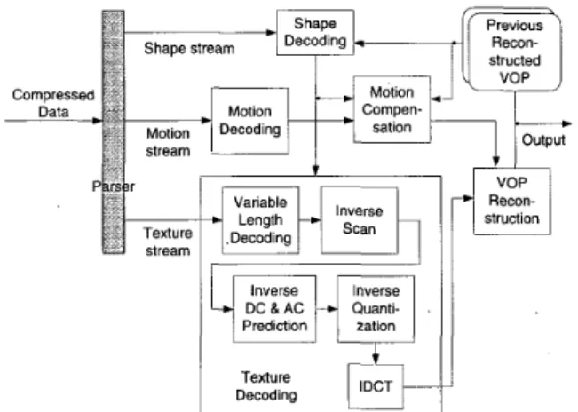
Nowadays most video data are represented and stored in digital form. Digital form data possess the advantages of fur- ther processing easily. Moreover, a lot of data compression technique can be applied for digital data. Data compression is essential because of limited communication channel and finite storage media space. After compression, the original digital data is transformed to compressed format called bitstream. A bitstream is composed of hundreds to millions of single bit whose value can be one or zero. It contains necessary infor- mation, including coded data and header information, for de- coder to transform it into its original uncompressed format, with a little distortion indistinguishable to human. Parsing is to extract header information and coded data correctly accord- ing to the compression rules. A parser can be regarded as a pre-processing unit in a video decoding system, as shown in Figure 1 [l].
Generally speaking, the implementations
of
bitstream parser can be divided into two classes. One is the dedicated decoder based on FSM [3][4]. It can achieve higher perform- ance and more cost-effective with the penalty of lacking flexibility. A programmable architecture is the other solution. The versatile VLD chip design proposed by Yang [5] can parse bitstreams of H.261 and JPEG. Additionally, the exten- sions of a RISC core for bitstream parsing and VLD proposed by Berekovic [6] can enhance the performance of bitstream processing for a conventional RISC.In previous designs for MPEG-2 [2] or other video coding systems, a dedicated decoder is usually adopted as a front-end
decoder. In newer system, like MPEG-4, however, more complicated and flexible bitstream structure is required so as to provide more functionality. Such requirements lead the front-end decoder to be capable of flexible decoding. Al- though a RISC processor could provide such capability, it will lead to the performance degradation due to its inefficiency for bit-level processing. This motivates the research for flexible and efficient parser architecture design.
Previous Recon- Recon- struction
lr"
Prediction1
Decodino Texture$4
I-
- 1FIGURE 1. MPEG-4 Video Decoding System
BITSTREAM
STRUCTURE
ANALYSIS
A bitstream is composed of several codewords, which rep- resent some information or symbols while delivering multi- media data. The code lengths of codewords can be fixed or variable. In this section, how they form a bitstream and are handled will be presented.Bit-level Processing
To access and handle a bitstream, several functions are re- quired to perform bit-level processing. To see a piece of bit- stream, the piece should be right aligned. When the piece is read out and next piece of bitstream is required, the bitstream pointer should be advanced. Sometimes it is required to ad- vance the bitstream pointer until the number of bits left in the huffer is a multiple of 8. To append several bits to the bit- stream, the bits to be appended should be left or right shifted to the correct location. In brief, these functions all can be ac- complished by bit-wise SHIFT and OR.
Bitstream-level Processing
Cycle Task
8/13 33.21 Fixed-length
decode [6]
-
One or several bits form a codeword, which is the informa-tion hidden in the bitstream. The bitstream structure is the description about the relationship among codewords and how to concatenate separate codewords to form a complete bit- stream. From the bitstream structure, a real bitstream can be generated by concatenating several codewords sequentially. Therefore, in the process of decoding a bitstream, the code- word to be extracted next is unknown until current or previous symbol, or current position of the bitstream pointer is known. Due to this characteristic, the bitstream-level processing be- comes more complex because some decisions must be made according to current or previous symbol, or current position of the bitstream pointer such that bitstream parsing can be per- formed smoothly.
The bitstream syntax is used to describe the bitstream structure, including codeword descriptions, layer structure, and some decision-making functions. Basically, the bitstream structure defined in MPEG-4 video coding standards [ I ] is hierarchy. A video scene contains one or several visual ob- jects, which are composed of one or more video object layers. One instance of a video object layer at a given time is consid- ered as a video object plane. In a video object plane are some video packets, which include data of several macroblocks. In addition to motion and texture data as in MPEG-2 video, shape information of a macroblock is also provided. The bit- stream syntax used in MPEG-4 video bitstream structure are listed in the following:
Fixed-length code: A codeword whose length is known ex- ists in the bitstream.
MOPS %
49.01 30.89 Variable-length code: The codeword is variable-length
coded. So, Its code length and value can be acquired by VLC table lookup.
Layer transformation: This syntax exists when the follow- ing part of a bitstream represents the information of another layer.
Loop: A series of codeword appears in the bitstream for several times.
Loop Total Decision-making: The following bitstream structure must
be decided. The branch condition may depend on the value of
previously extracted codeword or the coming codeword.
0.37 0.23
3 0.88
--_
100 158.67 100Code calculation: The value of previously extracted code- word will be modified for future condition checking.
From the above paragraphs, it is clear that VLC table- lookup, decision-making, and comparison are the key opera- tions required to accomplish bitstream-level processing.
COMPLEXITY
ANALYSIS
Analysis Approach
As the characteristics of bitstream-level processing have been explored, the computational complexity of MPEG-4 video bitstream parsing is analyzed by applying a RISC-based computation model. The computational complexity is defined as the required clock cycle count for bitstream parsing. Since the necessary bitstream syntax has been found out, each syn- tax can be regarded as a task performed while parsing a bit- stream. Thus, the total complexity of bitstream parsing can be acquired by calculating the product of each task count and clock cycle count each task needs. It is shown in the following equation:
To find out each task count, MPEG-4 video software de- coder is profiled on workstations so as to obtain number of times some functions called. Besides, statistical analysis is used for some tasks. To find out clock cycle count of each task, the instruction set of a general RISC core [7] is analyzed. Analysis Result
The analysis result is shown in Table 1 . The data are based on the test sequence bream in size 720x480 with three objects, 300 frames. The task item I' Decision-making (P)" represents
that the branch condition depends on the value of previously extracted codeword, while the item 'I Decision-making (N)"
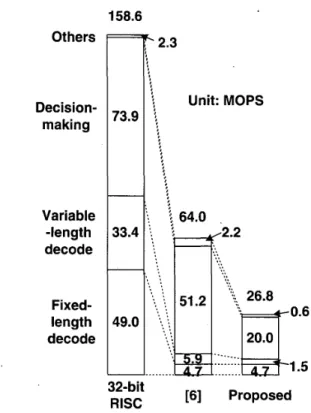
stands for that the branch condition depends on the value of previously extracted codeword. The task "Code calculation" is ignored here due to its low appearance frequency. From the table, half of MOPS is spent on decoding fixed-length and variable-length codes, while other half is spent on Branch. The total MOPS required by a general RISC core to perform bitstream parsing is about 160 MOPS.
TABLE 1. Complexity Analysis Result
Variable-length decode
1
4":':
I
::11
10.571.
33.421
21.071
Decision- 24.52 25.85 16.29 makin 11/14 27.34 48.05 30.28 Decision- makin NI
LayerI
4I
3.4811
1.96I
1.241
TransformationARCHITECTURE
DESIGN
Proposed Instruction Set
To enhance bitstream processing, it is necessary to propose a new instruction set to parse a bitstream more efficiently. From the analysis result, the parsing efficiency for a RISC core is degraded for extracting fixed-length and variable- length codewords and checking branch conditions. The pro- posed instruction set is listed in the following:
FLD: This instruction is used for fixed-length decoding. Besides, advancing the bitstream read pointer until the next bytealign position is supported.
VLD: This instruction is used for variable-length decoding.
213 Code
Calculation FNC: This instruction is used for layer transformation.
CAL: This instruction is used for code calculation. The op- eration to be performed can be arithmetic or logical opera- tions.
213 213 1
FOR: This instruction is used for loop.
BRANCH: This instruction can support up to two branch conditions checking.
Proposed Architecture
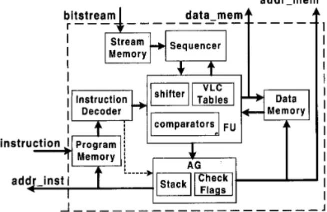
From the proposed instruction set, the architecture is com- posed of four major units: functional unit (FU), address gen- eration unit (AG), instruction decoder (INSTDEC), and a se-
memory. It is regarded as the controller of the .whole paring processor. To support all-layer parsing, stack implementation is included here for three circumstances: layer transformation, Ictoping, and branch instruction with conditions met.
INSTDEC decodes the executing parsing instruction in or- der to generate necessary data and control signals for se- quencer, FU, and AG. The sequencer shifts the incoming bit- stream to the position where the segment to be parsed in fed into FU.
The parsing flow is described as follows. At first, bitstream and parsing instructions are loaded into stream memory and program memory, separately. Bitstream is fed into a se- quencer. FLD extracts codeword from output stream of se- quencer according to data length denoted in parsing instruc- tion. Instruction VLD performs VLC table-lookup. The del, coded codeword of FLD or VLD is written into data memory arhose address is generated by AG. The decoded data, which are required by motion, texture or shape decoder in latter stage, can be the outputs of the proposed parsing processor by controlling the AG. BRANCH checks the branch conditions denoted in the instruction field and the comparison result is sent to AG to determine next parsing sequence. When FOR or FNC is executed, AG is controlled to generate correct address for fetching next parsing instruction. CAL performs operation on previously decoded symbol in FU and restores it in data memory.
quencer. The proposed parsing processor architecture is
shown as Figure 2. ~ e ~ o r m a n c e ~~~l~~~~~~
In the proposed architecture, one clock cycle is required to accomplish variable-length decoding by table-lookup, while a general-purpose RISC spends much more clock cycles [7]. Besides, it can accomplish two branch conditions checking in one branch instruction. The performance comparison in clock cycle count of each task is shown in Table 2. The proposed iiistruction set outperforms RISC's in code-extraction. addr-mem A
-
-
-
-' 1 I IFIGURE 2. Parsing Processor Architecture
FU performs bit-level shift for fixed-length decoding, ar- ithmetic operation such as addition and subtraction for code calculation, comparison and bit-wise operation for branch. Thus, a shifter and VLC tables are included in it. Besides, 2 comparators to perform branch condition checking are em- bedded here.
TABLE 2. Performance Comparison
11
8/131
I
1 1
8/13 ' decode 6 decode 19/26 Variable-length 91261 I
1;
11
1.512.251,
makin P Decision- makin 3.6715.5In MPEG-4 video Main Profile Level 4, the maximum bi- AG generates memory addresses and control signals to in-
dicate read or write mode for program memory and data trate can reach 38.4 Mbi& and the MB rate is 489600 MB/s
[ 11. Under such circumstance, the resulting required MOPS of each architecture is shown in Figure 3. It’s clear that a gen- eral-purpose RISC core would spend about 160 MOPS, and the architecture in [6] would spend about 64 MOPS. However, the proposed architecture only takes about 27 MOPS. About 6 times speedup with 32-bit RISC is achieved.
Memory 158.6 9088 bits Others Decision- making Variable -length decode Fixed- length decode
-
-
73.9 33.4 49.0 2.3 : : hit: MOPS\
64.0 -0.6 -1.5 [6] Proposed 32-bit RISCFIGURE 3. Performance Comparison in MOPS
FIGURE 4. Chip Layout
CONCLUSION
The analysis of characteristics of bitstream-level process- ing and an MPEG-4 video bitstream parsing processor archi- tecture is presented in this paper. The processing power of bitstream processing is shown from the analysis. An instruc- tion set optimized for bitstream parsing is proposed according to the analysis result. The proposed architecture is based on a new proposed instruction set for bitstream parsing. The evaluation result shows the required MOPS of the proposed architecture is only 27 MOPS, which is much lower than that of a general RISC core, while the programmability and flexi- bility are supported.
REFERENCES
IMPLEMENTATION
The VLC tables required for VLC decoding are embedded in the system. Software to transform VLC tables defined in standards to HDL-code has been developed. About 24K gates are used for the architecture except for the memory. Among them, less than 7K gates are for VLC tables. The summary of chip features is listed in Table 3. The chip layout is shown in Figure 4.
TABLE 3. Chip Summary Technolopy
Chi0 Area
I
3.02 x 3.00 mm2I
TSMC 0.35um CMOS 1P4MI
Die AreaI
2.23 x 2.21 mm2I
I
Gate CountI
24,5 17 (memory excluded)I
I Sneed
I
40 MHzI
Power
1
250 mW @, 40 MHz, 3.3 V Package1
1OOC Q FP[I] ISOAEC JTCl/SC29/WGl1. N2.502~1, Generic Coding of Au- dio- Visual Objects: Visual 14494-2, Final Draft of Interna- tional Standard, Atlantic City, Dec. 1998.
[2] ISOAEC/JTC 1/SC29/WG11 Draft CD 13818-2 Recommenda- tion H.262 Committee Draff.
[3] J. H. Li, N. Ling, “Architecture and bus-arbitration schemes for MPEG-2 video decoder,” IEEE Transactions on Circuits and Systems for Video Technology, Vol. 9, No. 5, pp.727-736, Au- gust 1999.
[4] T. Onoye, T. Masaki, Y. Morimoto, Y. Sato, I. Shirakawa, “HDTV level MPEG2 video decoder VLSI,” pp.727-736, TENCON’95.
[5] K.-M. Yang, F. Fujiwara, T. Sakaguchi, A. Shimazu, “VLSI architecture design of a versatile variable length decoding chip for real-time video codecs,” IEEE Region
IO Conference on Computer and Communication Systems, pp.55 1-554, September 1990.
[6] M. Berekovic, G. Meyer, Y. Guo, P. Pirsch, “A multimedia RISC core for efficient bitstream parsing and VLD,” SPIE‘98. [7] J. L. Hennessy, D. A. Patterson, Computer Architecture: A
Quantitative Approach, second edition, Morgan Kaufmann Pub- lishers, Inc., 1996.