mobility (NEMO) and Internet Protocol mobility are gaining more and more importance. In this paper, we develop a Session Initia-tion Protocol (SIP)-based mobile network architecture to support NEMO for vehicular applications. We propose to form a mobile
ad hoc network (MANET) by the mobile hosts (MHs) inside a
vehi-cle or a cluster of vehivehi-cles. The MANET is connected to the outside world via a SIP-based Mobile Network Gateway (SIP-MNG), which is equipped with one or multiple external wireless interfaces and some internal IEEE 802.11 interfaces. The external interfaces of the SIP-MNG support Internet connectivity by aggregating user traffic to and from the Internet. In addition, exploiting the session information carried by SIP signaling, the SIP-MNG supports resource management and call admission control for the MHs. However, wireless access incurs charges, power consumption, and overhead of mobility management. So, it is desirable to allow the SIP-MNG to disconnect its external interfaces when necessary. To guarantee that users inside the mobile network will not lose any incoming request, we propose a push mechanism through short message service to wake up these wireless interfaces in an on-demand manner. We show the detailed signaling to support such a mechanism. The proposed system is fully compatible with existing SIP standards. Our real prototyping experience and some experimental results are also reported.
Index Terms—Mobile ad hoc network (MANET), mobile
com-puting, network mobility (NEMO), push mechanism, Session Ini-tiation Protocol (SIP), wireless network.
Manuscript received February 15, 2007; revised May 31, 2007 and July 16, 2007. The work of Y.-C. Tseng was supported in part by the Ministry of Education, Taiwan, R.O.C., under an ATU Program, by the National Science Council under Grant 93-2752-E-007-001-PAE, Grant 96-2623-7-009-002-ET, Grant 2221-E-009-058-MY3, Grant 2221-E-009-060-MY3, Grant 95-2219-E-009-007, Grant 95-2218-E-009-209, and Grant 94-2219-E-007-009, by Realtek Semiconductor Corporation, by the Ministry of Economic Affairs under Grant 94-EC-17-A-04-S1-044, by the Industrial Technology Research Institute, Taiwan, R.O.C., by Microsoft Corporation, and by Intel Corporation. The review of this paper was coordinated by Dr. L. Cai.
Y.-C. Tseng is with the Department of Computer Science, National Chiao Tung University, Hsinchu 300, Taiwan, R.O.C., and also with the Department of Information and Computer Engineering, Chung Yuan Christian University, Chung Li 32023, Taiwan, R.O.C. (e-mail: [email protected]).
J.-J. Chen is with the Department of Computer Science, National Chiao Tung University, Hsinchu 300, Taiwan, R.O.C. (e-mail: [email protected]).
Y.-L. Cheng was with the Department of Computer Science, National Chiao Tung University, Hsinchu 300, Taiwan, R.O.C. He is now with Alpha Networks Inc., Hsinchu 300, Taiwan, R.O.C. (e-mail: [email protected]).
Color versions of one or more of the figures in this paper are available online at http://ieeexplore.ieee.org.
Digital Object Identifier 10.1109/TVT.2007.906986
A
expect to connect to the Internet anytime and from any-where. Extensive research has focused on how to maintain the global reachability of a device without interruption even when it is moving around [1]–[3]. In [3], Rosenberg et al. have proposed methods for mobile devices to continue their sessions when the address changes. However, these hostmobil-ity management schemes manage the mobilmobil-ity and connectivmobil-ity
of mobile devices in an individual manner. Group mobility is not addressed. For example, in a transportation carriage, there may exist tens/hundreds of users roaming together. If managing users in a one-by-one manner, not only the core network has to track each user individually, but also, all users have to consume computation and radio transmission power to maintain their connectivity to the Internet. Clearly, supporting host mobility when users exhibit group mobility causes significant costs. Instead of tracking the individual users’ mobility, a concept called network mobility (NEMO) [4], [5] has recently been proposed. NEMO packs all users in a vehicle as a network unit and conducts mobility management through a gateway/router in the mobile network. Supporting vehicular networking services by NEMO provides the following advantages: 1) There is less power consumption for a mobile device to connect to the local gateway/router than to a base station (BS) outside the vehicle; 2) the complexity of mobility management is lower or even transparent for a mobile when connecting to a local gateway/router, and 3) there are fewer handoffs since the medium access control layer handoff only occurs on the central gateway/router rather than on all mobile devices, and the mobility management of a single gateway/router can ensure the reachability of the whole group of users inside the gateway/ router [6].
To support NEMO, the Internet Engineering Task Force (IETF) has created a working group where a Mobile
Internet-Protocol-Version-6-based NEMO (MIPv6-NEMO) protocol is
proposed [7]–[9]. In a mobile network, there is a central node called Mobile Router (MR) that can connect to the Internet and provide networking services for the attached mobile devices. The MR has a home network and is assigned with one or more address blocks belonging to the home network, which are called mobile network prefixes, which can be assigned to the attached devices. Whenever the mobile network changes location, the MR will update with its Home Agent (HA), so packets addressed to the mobile network prefixes will still
TSENG et al.: DESIGN AND IMPLEMENTATION OF A SIP-BASED MOBILE AND VEHICULAR WIRELESS NETWORK 3409
be routed to the mobile network from the home network. In addition to MIPv6-NEMO, the Session Initiation
Protocol-based NEMO (SIP-NEMO) is proposed in [10]. In SIP-NEMO,
central to the mobile network is a SIP NEMO Server (SIP-NMS) that is responsible for the mobility management of the mobile network. Each SIP-NMS has a SIP Home Server (SIP-HS) that records the current location of the SIP-NMS and forward requests to the SIP-NMS. SIP clients can communicate with each other directly without tunneling. So, SIP-NEMO also provides an additional way to achieve route optimization and tunnel header reduction for NEMO. However, both MIPv6-NEMO and SIP-MIPv6-NEMO schemes have the following shortcom-ings: 1) The wireless resource is limited and valuable, but both architectures do not consider how to manage wireless resources to guarantee quality-of-service (QoS) of sessions and how to dynamically adjust its bandwidth to the Internet. 2) Both methods use an always-on approach, which means that the central gateway/router has to continuously collect network advertisements and deal with handoffs, even when the network has no sessions for a long period of time. This will incur unnecessary charges and energy consumption for the external wireless interfaces. 3) For SIP-NEMO, in addition to existing SIP servers, extra servers such as SIP-HS and SIP Foreign Server (SIP-FS) are required. This will increase the implemen-tation cost for public transporimplemen-tation operators. 4) Widespread SIP-FS deployment is needed in all foreign network domains into which users may roam. This causes a significant barrier for such services to be widely accepted.
In addition, based on the NEMO concept, this paper pro-poses to combine the innate mobility and scalability of the mobile ad hoc network (MANET) with a SIP-based mobile network architecture to support vehicular networking services for users on the roads. Our system is designed over IPv4. Compared to SIP-NEMO [10], our system only needs an addi-tional SIP-based Mobile Network Gateway (SIP-MNG), which follows the SIP standard and is compatible with the existing SIP framework, in each mobile network. No extra servers are needed in foreign networks. In our implementation, the SIP-MNG connects to the intra-MANET by some IEEE 802.11 interfaces configured at the ad hoc mode and attaches to the Internet through one or more external wireless interfaces (such as Global System for Mobile Communications (GSM), General Packet Radio Service (GPRS), Personal Handyphone System (PHS), Third Generation (3G), World Interoperability for Mi-crowave Access (WiMAX), and IEEE 802.11 interfaces). These external interfaces allow the SIP-MNG to provide dynamic bandwidths to the Internet according to the users’ demand and roaming characteristics. For example, by exploiting the session parameters carried by SIP signaling (such as session type, codec, bandwidth requirement, etc.), our SIP-MNG can support resource management (RM) and call admission control (CAC) to guarantee the QoS of sessions. Therefore, wireless resources are efficiently utilized.
Although the aforementioned system is quite attractive, dial-ing on to the Internet (via wireless interfaces) incurs charges, power consumption, and maintenance overhead. When there is no Internet activity, it is desirable to disconnect the SIP-MNG’s wireless interfaces to save energy and cost. However, this will
result in users inside our system to be unreachable by other users. To solve this problem, we exploit the SIP session control feature and propose to establish a push server in the Internet as a representative of our system when being disconnected. When a SIP request arrives, we develop a push mechanism by dropping a short message to the SIP-MNG to “wake up” the connection by redialing to the Internet. Once the SIP-MNG resumes its connection, it informs the push server its contact address of the destined mobile host (MH). Via the contact, the push server can transfer the suspended session to the MH by the SIP session transfer. Therefore, the proposed push mechanism can guarantee reachability of users in the mobile network while saving energy, cost, and wireless resources.
The push mechanism has also been used in other applica-tions. In GPRS networks, an MH must activate a packet data protocol (PDP) context before the corresponding service can be used. However, maintaining a PDP context without actually using it will consume network resources. So, short messages are used in [11] to activate a PDP context on-the-fly. For a dual-mode handset (for instance, with cellular and wireless local area network (WLAN) interfaces), to reduce energy consumption, it is desirable to disable the handset’s WLAN module when it is not used. However, this will prevent the handset from receiving incoming voice over IP (VoIP) calls from the WLAN interface. To solve this problem, Lin et al. [12] use a paging mechanism via the cellular interface to inform the handset to activate its WLAN module. Then, the VoIP call can be connected via the relatively inexpensive WLAN. However, both [11] and [12] involve some modifications on SIP components and end devices to support such functions, which is undesirable. In addition, because of the overhead to go through the push procedure, both approaches may suffer from the timeout problem if the callee’s response time exceeds a predefined threshold. In our architecture, the standard protocols in SIP servers and SIP clients are unchanged. In addition, with an external server and SIP call control feature, our approach can effectively relieve the timeout problem.
This paper is organized as follows: Section II introduces our system architecture to support vehicular networking services and the design motivation. Detailed system operations are presented in Section III. The push mechanism is discussed in Section IV. Section V presents our prototyping experience and performance measurement results. Conclusions are drawn in Section VI.
II. SYSTEMARCHITECTURE ANDMOTIVATION
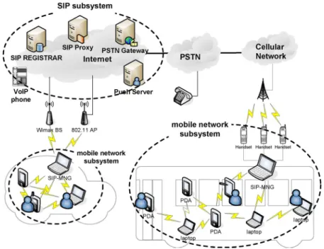
Fig. 1 shows our SIP-based mobile network architec-ture, which contains a mobile network subsystem and a SIP
subsystem. The former is a SIP-based mobile network
connect-ing to the Internet. The latter includes some servers to support SIP-based networking services.
Central to the mobile network subsystem is SIP-MNG. It is equipped with one or multiple wireless interfaces (such as GSM, GPRS, PHS, 3G, WLAN, and WiMAX interfaces) that can dial up the Internet and some IEEE 802.11 interfaces to connect to the internal MANET. In real applications, cellular interfaces may be applied in freeways, country areas, and
Fig. 1. System architecture.
trains, while WLAN and WiMAX interfaces may be applied in hot spot and metropolitan areas. The MANET consists of a set of MHs, each equipped with an 802.11 interface con-figured at the ad hoc mode. Because real-time services are stringent in responsiveness, routing in MANET is supported by a proactive protocol such as destination-sequenced distance-vector (DSDV) [13] and clustered gateway switch routing (CGSR) [14], which will attempt to maintain consistent up-to-date routing information at each host.
The SIP subsystem has four components, i.e., SIP regis-trar, SIP proxy, Public Switched Telephone Network (PSTN) gateway, and push server. The SIP registrar is a database that contains the users’ subscription and status information. Users need to send their SIP registrar SIP REGISTER request mes-sages to periodically update their current locations or when the IP changes. The SIP proxy is responsible for routing SIP mes-sages. The SIP registrar and SIP proxy are logical entities and are commonly implemented in a single host called a SIP server. The PSTN gateway interconnects the Internet and the PSTN. So, with the PSTN gateway, SIP servers can set up/receive calls to/from the PSTN, respectively. The push server is to support our push mechanism and can “wake up” the SIP-MNG when its wireless interfaces are disconnected from the Internet. This can prevent incoming requests to the mobile network subsystem from loss.
Before presenting the detailed system operations of our system, we first introduce our design motivations.
• Saving charges of Internet access: Table I shows the charge plans of the different types of wireless interfaces. There are three types: 1) charge by time; 2) flat rate, and 3) charge by packet. Clearly, for charge plans 1) and 2), accessing the Internet for a group of users in a vehicle through a few wireless interfaces can save a great deal of charges for individuals. For plan 3), operators can save wireless resources.
TABLE I
CHARGEPLANS OFDIFFERENTTYPES OFWIRELESSNETWORKS
• QoS guarantee: For real-time and multimedia sessions, QoS has to be guaranteed. Exploiting the session informa-tion carried by SIP signaling, our SIP-MNG is designed with CAC and RM mechanisms to guarantee the QoS of real-time or multimedia applications.
• Push mechanism to save charges, power consumption, and wireless resources: Considering that the current battery technology for cell phones can operate 2–5 h in the active mode and five–14 days in standby mode, it is desirable to disconnect the cellular interfaces of SIP-MNG (by putting them in standby mode) to save power consumption when no Internet activity exists. In addition, this can save charges for plans 1) and 3), too. Moreover, SIP-MNG does not need to collect network advertisements to maintain global reachability. Via SIP session control and short message service (SMS), we design a push mechanism to allow the wireless interfaces to stay offline when there is no Internet connection and to be “woken up” when necessary.
• An added service for public transportation operators: The public transportation operators can use our system as an added service to attract customers. In addition, adding management functions (such as accounting) becomes easy via SIP-MNG.
• Backward compatibility: Our goal is to serve existing SIP clients without modification. So, we design our system by
TSENG et al.: DESIGN AND IMPLEMENTATION OF A SIP-BASED MOBILE AND VEHICULAR WIRELESS NETWORK 3411
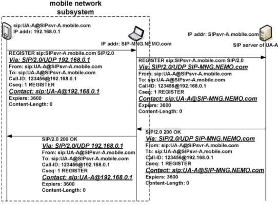
Fig. 2. SIP registration procedure in our SIP-based mobile network.
adding some new servers that can work transparently with to existing SIP clients.
• Reducing handoffs: When a vehicle moves from one BS to another, BSs have to handle a large number of handoff events if host mobility is used. With our architecture, BSs only have to handle the mobility of the SIP-MNG, thus significantly reducing the BSs’ load.
• Saving the power consumption of MHs: Since an MH connects to the Internet via the local SIP-MNG, its power consumption is significantly reduced.
• Decreasing the complexity of MHs: Since handoff events are handled by the SIP-MNG, MHs do not have to do movement detection and location update. The design of MHs is simplified. This is also known as movement
transparency.
III. BASICOPERATIONS OF THESIP-BASED
MOBILENETWORK
In this section, we discuss the basic network opera-tions in our system. Since MANET is considered a private network, to provide Internet access, the SIP-MNG serves as a Network Address Translation (NAT) server for MHs and is responsible for the translation of SIP messages. To achieve the NAT traversal for SIP, techniques such as Application Layer Gateway (ALG) [15], Simple Traversal of User Datagram Protocol Through NATs (STUN) [16], and Interactive Connectivity Establishment (ICE) [17] have been proposed. Here, we adopt the ALG scheme in our SIP-MNG. Below, we will discuss the entrance and ses-sion establishment procedures, and CAC, RM, and handoff mechanisms.
A. MH Joining the Mobile Network
When a mobile device moves into a vehicle with the pro-posed SIP-based mobile networking services, its IEEE 802.11 interface will detect the existence of the network. After at-taching to the mobile network, the MH will get a new IP address from the SIP-MNG. With this address, the MH can actively send a SIP REGISTER message to its SIP server to update its contact information. The REGISTER message will trigger the SIP-MNG to serve as a representative of the MH. Fig. 2 shows the detailed procedure of the SIP registra-tion. In this scenario, we assume that the MH UA-A gets an IP address 192.168.0.1 from SIP-MNG, and its SIP URL is sip:[email protected]. The addresses of the SIP-MNG and UA-A’s SIP server are SIP-SIP-MNG.NEMO.com and SIPsvr-A.mobile.com, respectively. In the registration proce-dure, UA-A first sends a SIP REGISTER message to its SIP server with Via and Contact fields equal to 192.168.0.1 and sip:[email protected], respectively. Since the SIP-MNG monitors and translates all SIP messages to/from the Inter-net, it will capture the REGISTER message. On intercepting the message, the SIP-MNG will record UA-A’s affiliation by adding UA-A’s information into a SIP_client_table and relay the message by translating the Via and Contact fields into SIP-MNG.NEMO.com and sip:[email protected], re-spectively. On receiving the SIP REGISTER message, the UA-A’s SIP server will update UA-A’s information and then reply a SIP 200 OK message. Since the Via field in the REGISTER request is translated into the SIP-MNG’s address, the 200 OK message will be forwarded to the SIP-MNG. In addition, with the SIP-MNG’s address as the contact address, the UA-A’s SIP server can later forward SIP request messages destined for UA-A to the SIP-MNG, which will then relay them
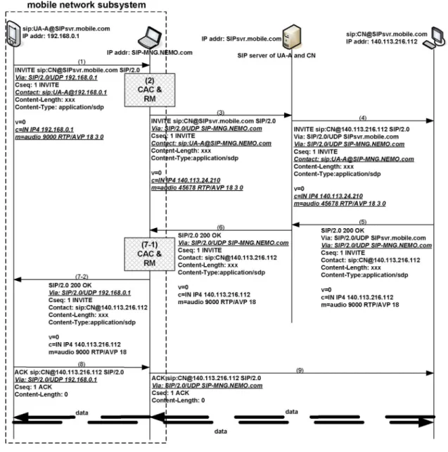
Fig. 3. Message flow to set up a session.
to UA-A. Upon receipt of the 200 OK message from UA-A’s SIP server, the SIP-MNG will translate the Via and Contact fields back to UA-A’s address, and relay the SIP response to UA-A. Then, the SIP registration procedure is completed.
B. Session Setup Procedure and CAC and RM Mechanisms
In this subsection, we present how a session is established between an MH in the MANET and an external Corresponding Node (CN). We also discuss how our SIP-MNG supports CAC and RM. Recall that a SIP-MNG has one or more external interfaces. An interface is active if it has been dialed up on the Internet; otherwise, it is idle. RM is responsible for evaluating the required bandwidth of a requested session and assigning a serving external interface for the session. The required band-width can be estimated by the Session Description Protocol (SDP) [18] provided in the SIP signal. If any active wireless interface has sufficient spare resource, RM will assign it to the session. Otherwise, the RM will activate a new wireless interface to serve the session. If all wireless interfaces are full, CAC will drop the SIP signal and reject the request.
Here, we use a voice call request as an example to describe the detail message flow of session setup, CAC, and RM. Fig. 3 depicts the message flow, with some SIP headers omitted for simplicity. We assume that UA-A’s IP address and SIP URL are 192.168.0.1 and sip:[email protected], re-spectively. CN’s IP address and SIP URL are 140.113.216.112 and sip:[email protected], respectively. For simplicity, UA-A and CN use the same SIP server, whose address is SIPsvr.mobile.com. The SIP-MNG’s address is SIP-MNG. NEMO.com. The corresponding call setup steps when UA-A calls CN are as follows.
1) UA-A sends a SIP INVITE to the SIP server to invite CN. Fields c (connection information) and m (media description) in the SDP are set to the connection address (192.168.0.1) and port number (9000), respectively (by which UA-A can receive data from CN). Field m also describes that the requested session is audio, so RM can tell that this is a real-time/multimedia session.
2) When intercepting the SIP INVITE message, the SIP-MNG will initiate the CAC and RM procedures. CAC
TSENG et al.: DESIGN AND IMPLEMENTATION OF A SIP-BASED MOBILE AND VEHICULAR WIRELESS NETWORK 3413
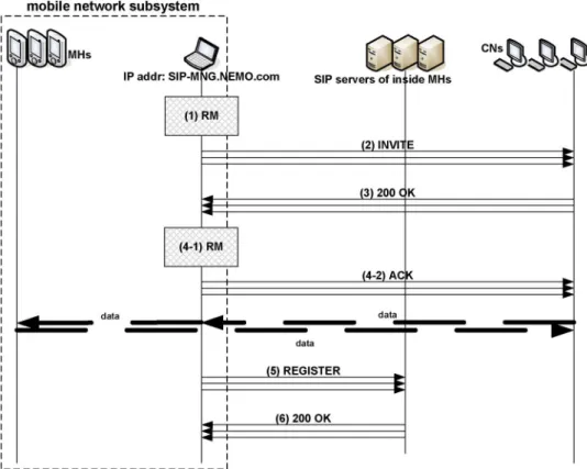
Fig. 4. Message flow of handoff.
will accept the requested session if RM returns ok and reject the session otherwise. RM includes the follow-ing three steps: a) Evaluate the required bandwidth, b) allocate a wireless interface for the session if there is enough bandwidth, and c) return the status ok/failure to CAC. Since the codec information can be derived from field m (18 = G.729, 3 = GSM, and 0 = G.711 mu-law), and the default packetization interval is 20 ms, the required bandwidth can be predicted. If there is no resource, the SIP-MNG will drop the SIP INVITE message and respond a SIP “480 Temporarily not avail-able” message to UA-A. Otherwise, the session will be recorded into a session table, and the SIP INVITE will be relayed to the SIP server after translation. Since the SDP may provide multiple candidate codecs for the ses-sion, RM will reserve the maximum required bandwidth for the session. For sessions with best-effort property (which can be known by field m), the SIP-MNG may reserve one or a few wireless interfaces dedicated to them. For such best-effort sessions, RM will skip the resource evaluation step and directly allocate an interface for it.
3) Then, the fields Via, Contact, c, and m of the SIP INVITE message are translated. In this example, the (connection address): (port) is translated from 192.168.0.1:9000 to 140.113.24.210:45678.
4) On receiving the SIP INVITE message, the SIP server forwards it to the CN, which will register the caller’s address as 140.113.216.112.
5) The CN then replies with a SIP 200 OK message, where it chooses G.729 as the codec to communicate with UA-A.
According to the Via header in the received SIP INVITE message, this 200 OK message will be sent back to the SIP server at SIPsvr.mobile.com.
6) Upon receipt of the 200 OK message, the SIP server forwards it to the address SIP-MNG.NEMO.com. 7) When the SIP-MNG receives the 200 OK message, RM
will update the session table according to the final media information. Then, the SIP-MNG translates the 200 OK message and relays it to UA-A.
8) UA-A feedbacks the SIP ACK message to the CN directly according to the contact information in the received 200 OK message.
9) The SIP-MNG relays the SIP ACK message to CN after translating the Via header. Then, the call is established.
C. Handoff Procedure
As the vehicle moves, an external interface may change its network domain, and the SIP-MNG may change its active interface. In both cases, a handoff happens. The SIP-MNG must recover sessions on these handoff interfaces by sending re-INVITE messages and maintain the global reachability of all MHs in MANET by sending re-REGISTER messages. Since recovering ongoing sessions are more urgent, it will be done first. Below, we outline the detail steps (refer to Fig. 4).
1) According to SIP_client_table and the session table, the SIP-MNG retrieves the endpoint MHs and CNs of the ongoing sessions on each handoff interface.
2) The SIP-MNG then sends each CN a SIP INVITE mes-sage to reinvite it.
Fig. 5. Sleep procedure.
3) A CN, on receiving the SIP INVITE message, will regis-ter the new contact address and port of the MH. Then, the CN replies a SIP 200 OK message.
4) On receiving the 200 OK messages, the SIP-MNG will update the session table and reply the corresponding CN a SIP ACK message. Then, the session between the CN and the MH can be continued.
5) After recovering all handoff sessions, the SIP-MNG will send a SIP REGISTER message for each MH that has changed to a new external interface to update its contact address.
6) When a SIP server receives the above SIP REGISTER message, it will update the corresponding MH data and reply a SIP 200 OK message. After this, all MHs are guaranteed to be reachable from the outside.
D. MH Leaving the Mobile Network
When an MH leaves the mobile network, it may detect other networks and update its contact information by sending a SIP REGISTER message. If there is an ongoing session, it can be resumed by SIP re-INVITE. However, since the MH does not deregister with the SIP-MNG, the SIP-MNG will keep its information in the SIP_client_table. If the MH has an ongoing session before it leaves, the SIP-MNG will still reserve resource for the session. Fortunately, if a SIP request arrives, because the MH does not exist in the network, a new session will not be set up. However, the allocated resource will never be released. To solve this problem, we suggest setting a timer for each session and integrating the SIP-MNG with the underlying routing protocol in MANET. If the SIP-MNG finds that the MH does not exist after the timer times out, the corresponding resource will be recycled. Note that the SIP-MNG can determine whether a specific MH exists or not by searching the corresponding entry in the routing table. Alternatively, the SIP OPTIONS message can be used to query the capability of a SIP client or server. The message should be responded with a SIP 200 OK response with the supported capabilities. This can be used to determine an MH’s existence.
IV. PROPOSEDPUSHMECHANISM
Our system allows the external interfaces of SIP-MNGs to be disconnected when there is no Internet connection. When any interface is connected, the mobile network becomes a part of the Internet, so all sessions can be handled as usual. When all interfaces are disconnected, if an outgoing SIP request is sent by a user in the mobile network, the SIP-MNG can buffer the invitation, dial up on to the Internet, register this user with the SIP registrar, and then send the invitation to the callee. However, when the mobile network is out of reach from the Internet, an incoming SIP request cannot be completed. To solve this problem, we propose a push mechanism.
In our push mechanism, the SIP-MNG will carry out a sleep
procedure when it decides to disconnect from the Internet.
Recall that there is a push server in the SIP subsystem (refer to Fig. 1). The SIP-MNG will solicit the push server as its agent during the disconnection period. When an incoming SIP request arrives, the push server will be notified first and will trigger a wake-up procedure, which includes a wake-up process and a session transfer process. In the wake-up process, the push server will activate the SIP-MNG via SMS and establish a connection with the caller to hold the session. After the SIP-MNG reconnects to the Internet, the transfer process will help build the link between the caller and the internal callee. This way, the SIP-MNG can stay offline but remain reachable from the Internet.
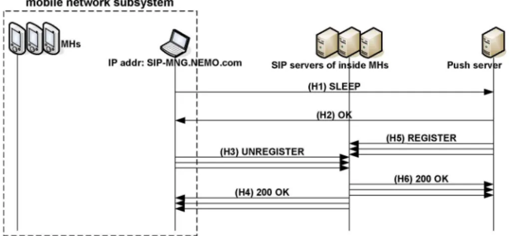
A. Sleep Procedure
To avoid modifying the existing SIP standard, the push server works as an agent for users inside the mobile network when the SIP-MNG is disconnected from the Internet. The sleep procedure is to inform the SIP server to redirect all SIP messages destined to mobile network users to the push server.
Fig. 5 shows the message flow of the sleep procedure. When there is no Internet connection, the SIP-MNG may initiate the sleep procedure by sending a sleep request to the push server (H1). The sleep request includes the SIP Uniform Resource Identifiers (URIs) of the MHs inside the mobile network and the Mobile Station International Integrated Services Digital
TSENG et al.: DESIGN AND IMPLEMENTATION OF A SIP-BASED MOBILE AND VEHICULAR WIRELESS NETWORK 3415
Fig. 6. Wake-up process.
Network Number (MSISDN) of one of the cellular interfaces of the SIP-MNG. The MSISDN will later be used by the push server to notify the SIP-MNG of new incoming SIP requests via short messages.
The push server maintains a gateway table and a SIP client
table. Each entry in the gateway table tracks the status of one
SIP-MNG and includes four fields, i.e., gateway id, status, MSISDN, and IP address. Each entry in the SIP client table is to track one MH and includes three fields, i.e., SIP URI, SIP-MNG id, and registration expiration time. On receiving the sleep request from the SIP-MNG, the push server updates these two tables and marks the status of the SIP-MNG as offline. The push server then replies an OK to the SIP-MNG (H2). Upon receipt of the OK message, the SIP-MNG will generate REGISTER messages for all internal SIP clients to their corresponding SIP servers (H3) with an EXPIRE value of 0 (which means unregister). In return, the SIP server will reply SIP 200 OK messages (H4). On the other hand, as soon as the push server replies an OK message to the SIP-MNG (H2), it also sends REGISTER messages for all MHs served by the sleeping SIP-MNG to their SIP servers with a nonzero EXPIRE value (H5). These REGISTER requests should contain the push server’s IP address in the CONTACT field, so that all future SIP INVITE requests to these MHs will be forwarded to the push server. Upon receipt of a REGISTER message, a SIP server will update its record and reply a SIP 200 OK message to the push server (H6). After step H4, the SIP-MNG can disconnect all its wireless interfaces, and after step H6, the push server will become the agent of the mobile network subsystem and send periodic REGISTER messages for it.
B. Wake-Up Procedure
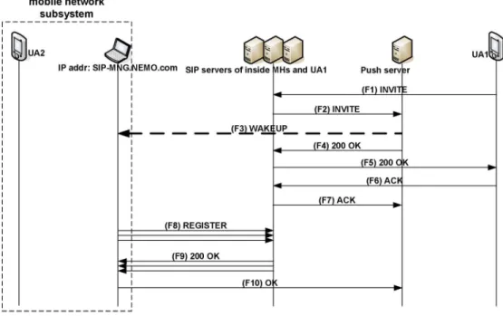
Consider a SIP request from a SIP client UA1 in the Internet to a client UA2 in the mobile network. To complete this session,
there are two parts in the wake-up procedure, i.e., wake-up process and session transfer process.
1) Wake-Up Process: Fig. 6 illustrates the message flow of
the wake-up process. To set up a session to UA2, UA1 first sends a SIP INVITE message to UA2’s SIP server containing the session information, connection address, and port number of UA1 in the SDP (F1). The SIP server will identify that the contact of UA2 is the push server and forward the INVITE to the push server (F2). The push server then checks its SIP client table and gateway table and retrieves UA2’s SIP-MNG information. Because the status of the SIP-MNG is offline, the push server will send a short message to the MSISDN registered by the SIP-MNG (F3). This short message carries the event type and IP address of the push server to inform the SIP-MNG to reconnect to the Internet. In the meantime, the push server will temporarily set up the session with UA1 to keep the session alive (F4–F7). This can prevent the SIP signaling from timeout. If this is a voice call request, to be more friendly, an option is to have the push server prepare a prerecorded voice to tell UA1 to wait for the call to be transferred. On the other hand, when the SIP-MNG receives the short message, it will reconnect to the Internet and reregister for all MHs inside the mobile network (F8, F9) using the IP address of any active external interface of the SIP-MNG in the CONTACT field. In addition, the SIP-MNG will reply an OK message to the push server via its Internet connection to update its status with the push server (F10).
2) Session Transfer Process: Next, the session needs to be
transferred from the push server to UA2. Fig. 7 depicts the message flow. The process is based on the REFER method [19] proposed by IETF to support session mobility. We comment that IETF also proposes an alternative third-party call control
(3pcc) [20]. Requiring no special servers, both REFER and
3pcc are standard SIP solutions to support session mobility and fit our needs well. We adopt the REFER method because it requires less effort for the push server.
Fig. 7. Session transfer process.
After accomplishing the wake-up process, the push server will send UA1 a REFER request containing the contact in-formation of UA2 in the Refer-To field (F11). This message triggers UA1 to invite UA2 using the contact in the Refer-To field. UA1 then replies a SIP 202 Accepted response to the push server to indicate its approval (F12). To inform the push server that it is establishing a session with UA2, UA1 will also send a SIP NOTIFY message to the push server with an indication of “SIP/2.0 100 Trying” in the message body (F13). On receiving the NOTIFY message, the push server will respond a SIP 200 OK response (F14). The push server then sends a SIP BYE request to UA1 to terminate their session (F15). UA1 will reply a SIP 200 OK (F16). However, the dialog between the push server and UA1 will be maintained until the subscription created by the REFER is terminated.
To set up a session with UA2, UA1 sends a SIP INVITE request to UA2 containing the SDP that describes the session information of UA1. Then, the rest of the SIP signaling follows the normal session setup flow (F17–F20). After the session between UA1 and UA2 is connected, UA1 will report to the push server the success of the session setup and terminate the Refer-To subscription by sending the push server a SIP NOTIFY message (F21) containing a Subscription-State header field with content of “terminated; reason = noresource.” Then, the push server will respond with a SIP 200 OK message (F19). The dialog between the push server and the UA1 will then be terminated. To stop acting as an agent of the mobile network subsystem, the push
server may send REGISTER messages for all SIP clients inside the SIP-MNG to their SIP servers with an EXPIRE value of 0 (F23). In response, the SIP servers will send 200 OKs (F24).
Note that an MH may simply leave the network without giving any notification. We have discussed some timeout mech-anisms to determine an MH’s existence. If the SIP-MNG knows that the callee has left the network, it will not activate any external interface. Otherwise, an interface will be activated, but no MH will accept the INVITE message. So, our system still works correctly.
To summarize, in our push mechanism, no change is made on the behavior of the SIP registrar and SIP proxy. SIP clients still use the standard SIP signaling. A push server can serve multiple SIP-MNGs at the same time. The REFER method is also a standard. So, the system is fully compatible with the existing SIP standards. Short messages and new signaling are supported by our proprietary SIP-MNG and push server. Each SIP client inside the mobile network subsystem can still use its original SIP server, SIP URI, and configuration.
V. EXPERIMENTALRESULTS ANDCOMPARISON
In this section, we will introduce our prototype of the proposed system, analyze its performance, and compare its signaling cost to the MIPv6-NEMO scheme with routing opti-mization. In the performance evaluation parts, we use voice call applications to test the performance. The performance indexes include call setup time, the maximum number of supported
TSENG et al.: DESIGN AND IMPLEMENTATION OF A SIP-BASED MOBILE AND VEHICULAR WIRELESS NETWORK 3417
Fig. 8. Testing environment of our SIP-based mobile network system.
calls, and handoff delay. We will also discuss the performance of the push mechanism.
A. Our Prototype
We have implemented a prototype of the proposed sys-tem. In our prototype, the SIP-MNG is implemented over the Linux Fedora Core Release IV. The command iptables and the library libipq [21] are used to carry out the NAT traversal and SIP-ALG (an application layer program to monitor and translate SIP messages). As to the external interfaces of SIP-MNG, we adopt the PHS WiWi Card MC-P300/P-Card MC-6550 and the Huawei E612 wideband code-division multiple-access (WCDMA) Personal Computer Memory Card International Association (PCMCIA) card to connect to the PHS and WCDMA cellular networks, respectively. Our current push server is implemented by C++ on Microsoft Windows XP. The push server contains a simple SIP stack and can support the SIP REFER method [19]. Both the SIP-MNG and the push server run an SMS agent to transmit/receive short messages. The communication protocol between the GSM interface and the SMS agent is achieved by the SMS AT commands [22]. To support multihop ad hoc routing, the MNs in the MANET all run the DSDV protocol.
The testing environment is shown in Fig. 8. MHs are IBM X23 notebooks equipped with ASUS WL-167G USB2.0 WLAN adapters configured at the ad hoc mode. They run the Microsoft Windows XP with Windows messenger 5.1 as their SIP client software. The SIP-MNG is an IBM T42 notebook running Linux Fedora Core Release IV, and a Nokia card phone 2.0 is equipped to access GSM SMS. To access the Internet, the SIP-MNG is equipped with an embedded 802.11 WLAN chipset and a cellular interface (Huawei E612 WCDMA PCMCIA card/PHS J88 cellular phone). The PHS phone in-terface is driven by the SIP-MNG via a P-Card MC-6550 PCMCIA adaptor. The push server is an ASUS Centrino note-book running the Microsoft Windows XP. It is also equipped with a Nokia card phone 2.0 to transmit short messages. An iptel SIP server [23] is used to serve as a server. In the Internet side, we have several SIP client terminals, including D-Link IP phone and WiFi phone. All SIP clients inside the
TABLE II
MEASUREMENT OFCALLSETUPTIME AND
CAPACITIES OFDIFFERENTINTERFACES
MANET or on the Internet use the SIP server as their home SIP server.
B. Call Setup Time and Maximum Number of Supported Calls
Based on the above environment, we have measured the call setup time and the maximum number of supported calls for different wireless interfaces. Some testing results are shown in Table II. Each experiment here and in the following subsections was repeated ten times. It shows that, to set up a call via a PHS J88 phone interface, it takes 1.58 s on average for MH2 to receive the ring tone of a call from an IP phone on the Internet. If it is via the WCDMA PCMCIA card/embedded IEEE 802.11b interface, it requires 1.44/1.11 s on average, respectively. We do not provide results of the GPRS interface because in our experience, a GPRS interface cannot provide enough bandwidth to support even one single voice call (the GPRS downlink bandwidth is only 28.8 kb/s, and the uplink bandwidth is even less). The call setup time by cellular in-terfaces is longer than that by the 802.11 inin-terfaces because connecting MH2 and the IP phone via a cellular interface has to go through four networks, i.e., the Internet, PSTN, the cellular network, and our MANET. However, connecting them via a wireless interface only goes though two networks, i.e., the Internet and our MANET. The proposed system allows multiple calls to be supported by a single interface. With a PHS interface, the SIP-MNG can support two concurrent voice calls with acceptable quality (< 1% packet dropping rate), while with one WCDMA interface, it can support up to five concurrent voice calls. Interestingly, with an IEEE 802.11b wireless interface, the SIP-MNG can support up to 12 concurrent voice calls with G.729 as the codec.
Fig. 9. Uplink traffic load against the number of concurrent calls using one PHS/WCDMA/802.11b interface.
We have also measured the uplink traffic load on a PHS/ WCDMA/802.11b interface (we did not measure the downlink load because the uplink bandwidth is lower than the downlink bandwidth in all existing cellular interfaces). Fig. 9 plots the uplink traffic load against the number of concurrent calls on a PHS/WCDMA/802.11b interface. As shown in Fig. 9, in the be-ginning, the uplink traffic load increases linearly as the number of calls increases. As the number of calls keeps increasing, the PHS’s curve will saturate after there are more than two calls, the WCDMA’s curve will saturate after there are more than five calls, and the IEEE 802.11b’s curve will saturate after there are more than 12 calls. This gives the maximum number of calls that can be supported in Table II. Our measured capacity for the 802.11b wireless interface is close to the analysis in [24], which claims that 11.4 G.729 calls can be supported, on average.
C. Handoff Delay
Fig. 10 illustrates the handoff procedure when an IEEE 802.11 interface is used. The handoff delay can be divided into five parts, i.e., T1 (the delay of layer 2 handoff for an MH switching from one AP to another), T2 (the delay of layer 3 handoff for an MH getting a new IP in a new subnet), T3 (the delay of SIP mobility), T4 (the delay from the SIP-MNG activating the SIP mobility procedure to the media session being resumed), and T5 (the reregistration latency for the SIP-MNG to update MHs’ contact information).
T1 and T2 are not the focus in our experiments because handoff rarely happens for cellular interfaces. In addition, lots of previous work [25], [26] has already provided empir-ical results of WLAN layer 2 and layer 3 handoff latencies. Therefore, we only evaluate T3, T4, and T5 for cellular and 802.11 interfaces. Table III shows the values of T3, T4, and
Fig. 10. Handoff procedure when an IEEE 802.11 interface is used. TABLE III
MEASUREMENT OFHANDOFFLATENCIES
TABLE IV
LATENCIES OF THEPUSHMECHANISM
T5 for different interfaces. For cellular interfaces, T4 consumes 967.37 ms on average, which is somewhat long. Fortunately, for cellular interfaces, handoff seldom happens because an operator’s network normally covers quite a large area. For cellular interfaces, T5 is 267.69 ms on average. This is why we do reinvitation before reregistration when a handoff occurs, or the SIP mobility latency will be further increased by 270 ms. For 802.11 interfaces, T3 and T4 are 268.26 and 279.54 ms, respectively, on average. This is much shorter than the cellular interface case. The reregistration delay T5 for such interfaces is only 42.34 ms on average.
D. Performance of the Push Mechanism
By the proposed push mechanism, our system allows the external interfaces of the SIP-MNG to be disconnected when there is no Internet connection. In this subsection, we evaluate the call setup latency when the SIP-MNG is disconnected from the Internet with our push mechanism. Table IV shows our testing results with different interfaces. If the interface is
TSENG et al.: DESIGN AND IMPLEMENTATION OF A SIP-BASED MOBILE AND VEHICULAR WIRELESS NETWORK 3419
a PHS J88 phone (in the countryside areas), with our push mechanism, it costs 23.03 s on average for MH2 to receive the ring tone from the IP phone. This latency consists of two major components, i.e., short message transmission time and wireless interface reconnection time. We found that the short message transmission time is 5.31 s on average, and the wireless interface reconnection time takes 13.05 s on average. Replacing the PHS interface with a Huawei E612 WCDMA PCMCIA card, it shows that the call setup time can be reduced to 18.77 s in the disconnected case. To further divide the cost, Table IV shows that the short message transmission time is also 5.31 s, and the wireless interface reconnection time is 8.47 s on average. If the wireless interface is an IEEE 802.11 interface, with our push mechanism, it shows that the average call setup time is 23.11 s, within which the wireless interface reconnection time requires 14.05 s on average. The call setup time in the 802.11 case is shorter than the cellular interfaces because SIP signaling only goes through two networks. However, no matter which type of interface is used, the call setup time is not short. This is why we design our push server to temporarily answer an incoming call to keep the session alive, or the caller may hang up before the call is established.
E. Comparison of Signaling Cost
Next, we compare the signaling cost of our proposed ap-proach and the MIPv6-NEMO scheme with routing optimiza-tion. We consider two cases. One is the offline case, where SIP-MNG is disconnected from the Internet; the other is the online case, where SIP-MNG is connected to the Internet. In the offline case, for SIP-MNG, there is no SIP signaling cost when it moves from one network domain to another. The external push server would be SIP-MNG’s representative, which answers and transfers incoming sessions for the mobile network. On the other hand, since the MIPv6-NEMO scheme does not support the disconnected feature, the MR still has to track network signaling and update with its HA at handoff. Suppose that the HA binding update cost is costHABU. In the
online case, the SIP signaling cost of SIP-MNG at handoff will be N× costSIP-reregistration+ S× costSIP-reINVITE, where N
is the number of MHs in the mobile network, and S is the num-ber of sessions between the mobile network and the Internet. On the other hand, the MIPv6-NEMO scheme with routing optimization will require a cost of costHABU+ M × costBU
at handoff, where we assume that the routing optimization approach based on binding update for network prefixes is used, and M is the number of CNs that are communicating with the mobile network. To summarize, in the online case, the SIP has its disadvantage in terms of signaling cost as compared to the MIPv6-NEMO scheme with routing optimization. However, in the offline case, our approach incurs a lower cost than the MIPv6-NEMO scheme, which may compensate some of the signaling cost in the online case.
VI. CONCLUSION
This paper has proposed a SIP-based mobile network ar-chitecture to support networking services on the roads. With
multiple wireless interfaces, a SIP-MNG can provide dynamic bandwidth to internal users based on their bandwidth require-ments. In addition, by allowing multiple sessions to share one interface, our system can help users or public transportation operators to save Internet access fees. Moreover, through our system, vehicles can provide Internet access to passengers with support of group mobility. By interpreting SIP signaling, our RM and CAC mechanisms inside the SIP-MNG can guarantee QoS for users. In addition, through session control and SMS, we have proposed a push mechanism to allow the SIP-MNG to stay offline when there is no calling activity and to be “woken up” when necessary. Our push approach can save energy and call charges while maintaining global reachability of users. In our architecture, we do not modify the current SIP client–server architecture and protocol.
A prototype has been developed, and some experimental results have been presented. For IEEE 802.11, WCDMA, and PHS networks, we demonstrated that it is feasible to allow multiple stations to share one interface. It is also shown that, by cellular interfaces, the call setup time and hand-off delay are longer than that by 802.11 interfaces, because connecting to the Internet via a cellular interface has to go through more networks. For our push mechanism, based on the current technologies, the call setup time is in the range of 20 s, which is somewhat long. So, we have designed the push server to temporarily pick up the session and apply the REFER scheme to transfer the session to the user inside SIP-MNG. The wireless interface reconnection time takes longest. Although this is not in the scope of this paper, we believe that a lot of re-search results can help reduce the reconnection time [27], [28].
REFERENCES
[1] C. Perkins, IP Mobility Support for IPv4, Aug. 2002. IETF RFC 3344. [2] D. Johnson, C. Perkins, and J. Arkko, Mobility Support in IPv6, Jun. 2004.
IETF RFC 3775.
[3] J. Rosenberg, H. Schulzrinne, G. Camarillo, A. Johnston, J. Peterson, R. Sparks, M. Handley, and E. Schooler, SIP: Session Initiation Protocol, Jun. 2002. IETF RFC 3261.
[4] T. Ernst, K. Uehara, and K. Mitsuya, “Network mobility from the InternetCAR perspective,” in Proc. 17th IEEE Int. Conf. Adv. Inf. Netw.
Appl., Mar. 2003, pp. 19–25.
[5] H.-Y. Lach, C. Janneteau, and A. Petrescu, “Network mobility in beyond-3G systems,” IEEE Commun. Mag., vol. 41, no. 7, pp. 52–57, Jul. 2003.
[6] E. Perera, V. Sivaraman, and A. Senevirarne, “Survey on network mobility support,” ACM SIGMOBILE Mobile Comput. Commun. Rev., vol. 8, no. 2, pp. 7–19, Apr. 2004.
[7] V. Devarapalli, R. Wakikawa, A. Petrescu, and P. Thubert, Network
Mobility Basic Support Protocol, Jan. 2005. IETF RFC 3963.
[8] T. Ernst, Network Mobility Support Goals and Requirements, Nov. 2006. IETF DRAFT: draft-ietf-nemo-requirements-06.
[9] T. Ernst and H.-Y. Lach, Network Mobility Support Terminology, Nov. 2006. IETF DRAFT: draft-ietf-nemo-terminology-06.
[10] C.-M. Huang, C.-H. Lee, and J.-R. Zheng, “A novel SIP-based route optimization for network mobility,” IEEE J. Sel. Areas Commun., vol. 24, no. 9, pp. 1682–1691, Sep. 2006.
[11] Y.-B. Lin, Y.-C. Lo, and C.-H. Rao, “A push mechanism for GPRS supporting private IP addresses,” IEEE Commun. Lett., vol. 7, no. 1, pp. 24–26, Jan. 2003.
[12] Y.-B. Lin, W.-E. Chen, and C.-H. Gan, “Effective VoIP call routing in WLAN and cellular integration,” IEEE Commun. Lett., vol. 9, no. 10, pp. 874–876, Oct. 2005.
[13] C. E. Perkins and P. Bhagwat, “Highly dynamic destination-sequenced distance-vector routing (DSDV) for mobile computers,” in Proc. ACM
[21] Netfilter. [Online]. Available: http://www.netfilter.org/
[22] C.-H. Rao, D.-F. Chang, and Y.-B. Lin, “iSMS: An integration platform for short message service and IP networks,” IEEE Netw., vol. 15, no. 2, pp. 48–55, Mar./Apr. 2001.
[23] SIP Express Router (SER). [Online]. Available: http://www.iptel.org/ser/ [24] W. Wang, S.-C. Liew, and V. O. K. Li, “Solutions to performance
prob-lems in VoIP over a 802.11 wireless LAN,” IEEE Trans. Veh. Technol., vol. 54, no. 1, pp. 366–384, Jan. 2005.
[25] A. Mishra, M. Shin, and W. Arbaugh, “An empirical analysis of the IEEE 802.11 MAC layer handoff process,” ACM SIGCOMM Comput.
Commun. Rev., vol. 33, no. 2, pp. 93–102, Apr. 2003.
[26] B. Aboba, Fast Handoff Issues, Mar. 2003. IEEE-03-155r0-I. IEEE 802.11 Working Group.
[27] H. Velayos and G. Karlsson, “Techniques to reduce the IEEE 802.11b handoff time,” in Proc. IEEE ICC, Jun. 2004, vol. 7, pp. 3844–3848. [28] S. Park, P. Kim, M. Lee, and Y. Kim, Parallel and Distributed
Comput-ing: Applications and Technologies. Berlin, Germany: Springer-Verlag,
2004, ch. Fast Address Configuration for WLAN, pp. 396–400.
Yu-Chee Tseng (S’91–M’95–SM’03) received the
B.S. degree in computer science from the National Taiwan University, Taipei, Taiwan, R.O.C., in 1985, the M.S. degree in computer science from the Na-tional Tsing Hua University, Hsinchu, Taiwan, in 1986, and the Ph.D. degree in computer and informa-tion science from Ohio State University, Columbus, in 1994.
He was an Associate Professor with Chung Hua University, Hsinchu, from 1994 to 1996 and with the National Central University, Taoyuan, Taiwan, from 1996 to 1999, and a Professor with the National Central University from 1999 to 2000. Since 2000, he has been a Professor with the Department of Computer Science, National Chiao Tung University, Hsinchu, where he is also currently the Department Chairman. He is also with the Department of Information and Computer Engineering, Chung Yuan Christian University, Chung Li, Taiwan. His research interests include mobile computing, wireless communication, network security, and parallel and distributed computing.
Yu-Li Cheng received the B.S. degree in
engineer-ing science and ocean engineerengineer-ing from the National Taiwan University, Taipei, Taiwan, R.O.C., in 1995 and the M.S. degree in computer science from the National Chiao Tung University, Hsinchu, Taiwan, in 2007.
Since 2001, he has been with the Wireless Broadband Product Division, Alpha Networks Inc., Hsinchu, as a Software Engineer. His research in-terests include wireless communication and mobile computing.