IEEE PHOTONICS TECHNOLOGY LETTERS, VOL. 12, NO. 9, SEPTEMBER 2000 1153
Q-Switched All-Fiber Laser with an Acoustically
Modulated Fiber Attenuator
Ding-Wei Huang, Wen-Fung Liu, and C. C. Yang
Abstract—An actively -switched all-fiber laser based on an acoustically modulated fiber attenuator was implemented for pro-ducing 1550.5 nm pulses of 3 J in pulse energy, 150 ns in pulse width, and 5 kHz in pulse repetition frequency. The fiber attenu-ator was combined with a fiber Bragg grating, which was used as the end mirror and the wavelength selector of the laser system. The fiber attenuator was implemented with the excitation of transverse vibration by a modulated acoustic wave. The transverse vibration or micro bending led to the coupling of the core mode and cladding modes. Through this mechanism, the feedback level from the fiber grating or the factor of the laser can be well controlled. The -switched fiber laser based on this scheme can be quite simple.
Index Terms—Bragg gratings, fiber lasers, -switching.
Q
-SWITCHING of erbium-doped fiber laser can provide simple high-pulse-energy light sources for various appli-cations [1]–[7]. Typically, acousto-optical modulation in a free-space cavity was used for implementing -switching. Re-cently, efforts have been made in increasing the output peak power by utilizing fiber optical nonlinearity for pulse compres-sion and increasing the waveguide mode size for higher pulse energy [6], [7]. A short pulse width of 2 ns [6] and a high pulse energy of mJ ( kW peak power) [7] have been achieved. However, the required free-space cavity section for the acousto-optical modulator represents a drawback, which is open for im-provement. It is expected that an all-fiber -switched laser can increase the efficiency and its robustness.In this letter, we report a novel -switched all-fiber laser based on an acoustically modulated fiber attenuator, which was combined with a fiber Bragg grating (FBG). In this application, the FBG was used as the end mirror and the wavelength selector of the laser system. The fiber attenuator was implemented with the generation of micro bending through an acoustically excited transverse vibration of fiber [8]. The micro bending resulted in the out-coupling of the core-mode power into cladding modes. Part of the cladding-mode power radiated and the rest might couple back to the core mode. To enhance the micro-bending effect and control the cladding mode distribution, a fiber sec-tion was etched with HF solusec-tion to reduce the cladding
diam-Manuscript received October 25, 1999; revised May 31, 2000. This work was supported by National Science Council, R.O.C., under Grants NSC 88-2215-E-002-012, NSC 88-2112-M-002-004, and NSC 88-2215-E-002-014. D.-W. Huang is with the Department of Electrical Engineering and Graduate Institute of Electro-Optical Engineering, National Taiwan University, Taipei, Taiwan, R.O.C.
W.-F. Liu is with the Department of Electrical Engineering, Chung Cheng Institute of Technology, Tahsi, Taoyuan, Taiwan, R.O.C.
C. C. Yang is with the Department of Electrical Engineering and Graduate Institute of Electro-Optical Engineering, National Taiwan University, Taipei, Taiwan, R.O.C. (e-mail: ccy@cc.ee.ntu.edu.tw).
Publisher Item Identifier S 1041-1135(00)07422-X.
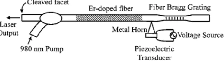
Fig. 1. Experimental setup of theQ-switched fiber laser.
eter down to 30 m. Also, to prevent the complications caused by the fiber grating reflection of the aforementioned back-cou-pled power, we combined the fiber attenuator with the grating by co-locating the etched section and the grating section. The combination of fiber attenuator and grating has other functions. However, they are out of the scope of this letter. Based on the mechanism discussed above, the -factor of the laser cavity was switched high and low by the acoustic wave. Pulses of around 150 ns in width and 3 J in pulse energy were obtained. The laser slope efficiency was 5.3%. This all-fiber -switched fiber laser can be quite compact.
Fig. 1 shows the experimental setup of the -switched fiber laser. The 72-cm-long erbium-doped fiber (2700-ppm doping concentration) was spliced to an FBG. Between the grating and erbium-doped fiber, the fiber was laterally glued onto the tip of a metal horn (made of aluminum), whose base was attached to a piezoelectric transducer (PZT), driven by a voltage source, for receiving mechanical vibration. This is the part of the setup for producing micro bending of the fiber. At the other end of the erbium-doped fiber, a wavelength division multiplexing (WDM) fiber coupler was connected for providing 980 nm of pump power, which was provided by an argon-laser pumped Ti : sapphire laser. At the very end, the cleaved fiber facet (4% reflectivity) was used as the output coupler of the laser. The whole cavity length was 136 cm. The grating has a length of 1.5 cm and a Bragg reflection window of 0.5 nm, centered at 1550.5 nm. The peak reflectivity was about 95%. As mentioned above, the fiber grating section was etched to reduce the cladding diameter down to 30 m. The length of this minimum cladding diameter was 2 cm with the 1.5-cm-long grating located at the center. With the two taper sections on both sides, the whole length of the etched section was about 5 cm. The metal horn was 1 cm in base diameter and 1.5 cm in length. Its tip was glued to the fiber about 2.5 cm from the grating center. Its base was glued to a thin PZT of 1.3 cm in diameter and 1.8 mm in thickness. The acoustic waves propagated with increasing intensity along the horn to its tip and translated the power to the fiber for generating transverse vibration or micro bending. The out-coupling of the core-mode signal reduced the power for Bragg reflection of the grating.
1154 IEEE PHOTONICS TECHNOLOGY LETTERS, VOL. 12, NO. 9, SEPTEMBER 2000
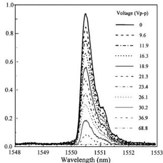
Therefore, the feedback level from the fiber grating decreased with the intensity of the acoustic wave or the applied voltage to the PZT. Fig. 2 shows the variation of normalized feedback intensity (normalized to the incident intensity of the fiber attenuator) or reflectivity with various applied voltage levels when the acoustic frequency is 713 kHz. One can see that as the peak-to peak (p-p) voltage increases to 68.8 V, the feedback level near 1550.5 nm is reduced to almost zero.
To see the response speed of the acoustically controlled fiber attenuator, we applied a periodical square-wave modulation with various frequencies to the sinusoidal voltage signal at 713 kHz. This led to a periodical on–off modulation of the acoustic wave. Fig. 3 shows the modulation response when the modulation frequency is 100 Hz. Part (b) of this figure shows the applied sinusoidal voltage under 100 Hz modulation with 50% duty cycle. Part (a) shows the variation of feedback level at 1550.5 nm of the fiber grating. One can see that the switch-off of feedback is faster than switch-on. The switching time depends on several parameters, including sound speed in fiber, the location of the horn tip along the fiber, the length of the etched fiber section, and the damping speed of vibration. When the acoustic wave is turned on, grating feedback switches off after the transverse vibration builds up in the etched section. From Fig. 3, this buildup time is in the range of 0.5 ms. On the other hand, it is expected to take longer to recover grating feedback after the voltage is turned off because the coupling effect between the core mode and cladding modes would not disappear until the transverse vibration of fiber damps away. From Fig. 3, one can see that the time scale for complete vibration damping is about 2.5 ms. Fig. 4(a) and (b) shows the similar results of the case when the frequency of square-wave modulation is increased to 5 kHz (again, 50% duty cycle). We can see the reduced amplitude of feedback (at 1550.5 nm) variation due to a delayed response. In this situation, the feedback starts to recover about 40 s after the voltage is turned off. Before turn-on of acoustic wave of the next cycle, only 60 s are left for feedback recovery. Because of the slow recovery and fast decay, the feedback level fluctuates between 0.06–0.27. Note that because the sampling rate of the used oscilloscope was not well set, the fast oscillation of the applied voltage in Fig. 4(b) does not represent the real acoustic frequency. The 6% feedback level during the period that the acoustic wave is off may lead to weak cw oscillation of the laser. This would reduce the efficiency of energy storage for -switching oscillation. An optimized design is expected to decrease this feedback level.
Fig. 5(a) and (b) shows the laser output pulse profile and the applied voltage with two different time scales. Here, the -switching frequency was 5 kHz, the applied voltage was 72 V (p-p), and the acoustic frequency was 713 kHz. The 980 nm pump power was 290 mW. In part (a), we can see that the -switched pulse appears about 20 s after the voltage is turned on. Then, in part (b), a close-up of the laser pulse reveals that the pulse width is about 150 ns.
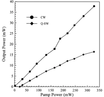
Fig. 6 shows the average power of laser outputs as functions of 980–nm pump power. The curves with filled circles and di-amonds represent the outputs of cw and -switching opera-tions, respectively. It was estimated that up to 80% of the input pump power was absorbed. The cw laser threshold is near 2 mW
Fig. 2. Variations of grating feedback level with various applied voltage values for exciting transverse vibration of the fiber.
Fig. 3. (a) Response of feedback level to a square-wave modulation of acoustic wave with modulation frequency at 100 Hz. (b) Variation of the applied voltage.
Fig. 4. Similar to Fig. 3, with the square-wave modulation frequency increased to 5 kHz.
and the slope efficiency is about 12%. The -switched laser threshold is about 20 mW and the slope efficiency is around 5.3%. Take the case of 290 mW pump power as an example. It
HUANG et al.: Q-SWITCHED ALL-FIBER LASER WITH ACOUSTICALLY MODULATED FIBER ATTENUATOR 1155
(a)
(b)
Fig. 5. Laser output pulse shape and the modulated applied voltage with two different time scales.
corresponds to the -switched average output power of 15 mW or pulse energy of 3 J/pulse. With the pulse width of 150 ns, the peak power is 20 W. Several parameters can be adjusted for optimizing laser operation, including the modulation frequency and duty cycle of acoustic wave, the applied voltage level, the diameter and length of the etched fiber, the location of the horn tip, the damping speed of fiber vibration, and the Bragg reflec-tivity of the fiber grating. The laser output spectrum was quite narrow and was beyond the spectral resolution of our spectrum analyzer, which is 0.08 nm.
In summary, we have implemented a -switched all-fiber laser using an acoustically modulated fiber attenuator, which was combined with a FBG serving as the end mirror and the wavelength selector. The feedback level of the fiber reflector could be varied by applying an acoustic wave to the fiber for generating transverse vibration or micro bending. Through the out-coupling of the core-mode power, the grating feedback level was controlled by the applied voltage. Pulses of several J per pulse with pulse width of about 150 ns and pulse repetition
Fig. 6. Average power of laser outputs in cw (filled circles) andQ-switched (filled diamonds) operations as functions of input 980 nm pump power.
frequency of up to 5 kHz were obtained. Because of the all-fiber nature, our laser system has the advantage of low insertion loss. However, the interaction between acoustic waves and fiber might represent a constraint of operating such a laser system at a high frequency [9]. Hence, developing such a laser system with high pulse energy and low frequency would be a reason-able direction. Nevertheless, an optimized design, including the relative sizes and locations of those parts in the fiber system and the use of an acoustic damper, is expected to improve the extinc-tion ratio and, to an extent, the switching speed.
REFERENCES
[1] P. R. Morkel, K. P. Jedrzejewski, E. R. Taylor, and D. N. Payne, “Short-pulse, high-power Q-switched fiber laser,” IEEE Photon. Technol. Lett., vol. 4, no. 6, pp. 545–547, 1992.
[2] A. Chandonnet and G. Larose, “High-power Q-switched erbium fiber laser using an all-fiber intensity modulator,” Opt. Eng., vol. 32, no. 9, pp. 2031–2035, 1993.
[3] F. Seguin and T. Oleskevich, “Diode-pumped Q-switched fiber laser,” Opt. Eng., vol. 32, no. 9, pp. 2036–2041, 1993.
[4] G. P. Lees, A. Hartog, A. Leach, and T. P. Newson, “980 nm diode pumped erbium3+/ytterbium3+ doped Q-switched fiber laser,” Electron. Lett., vol. 31, no. 21, pp. 1836–1837, 1995.
[5] G. P. Lees, D. Taverner, D. J. Richardson, L. Dong, and T. P. Newson, “Q-switched erbium doped fiber laser utilizing a novel large mode area fiber,” Electron. Lett., vol. 33, no. 5, pp. 393–394, 1997.
[6] Z. J. Chen, A. B. Grudinin, J. Porta, and J. D. Minelly, “Enhanced Q-switching in double-clad fiber lasers,” Opt. Lett., vol. 23, no. 6, pp. 454–456, 1998.
[7] H. L. Offerhaus, N. G. Broderick, D. J. Richardson, R. Sammut, J. Caplen, and L. Dong, “High-energy single-transverse- mode Q-switched fiber laser based on a multimode large-mode-area erbium-doped fiber,” Opt. Lett., vol. 23, no. 21, pp. 1683–1685, 1998.
[8] H. S. Kim, S. H. Yun, I. K. Kwang, and B. Y. Kim, “All-fiber acousto-optic tunable notch filter with electronically controllable spectral pro-file,” Opt. Lett., vol. 22, no. 19, pp. 1476–1478, 1997.
[9] K. De Souza, D. O. Culverhouse, and T. P. Newson, “Dual-operation Q-switched erbium-doped fiber laser for distributed fiber sensing,” Elec-tron. Lett., vol. 33, no. 24, pp. 2040–2042, 1997.