Separation and Purification Technology 58 (2007) 61–67
Nano-bubble flotation technology with coagulation process for
the cost-effective treatment of chemical mechanical
polishing wastewater
Jen-Chieh Tsai
a, Mathava Kumar
a, Shen-Yi Chen
b, Jih-Gaw Lin
a,∗aInstitute of Environmental Engineering, National Chiao Tung University, 75 Po-Ai Street, Hsinchu 300, Taiwan bDepartment of Safety, Health and Environmental Engineering, National Kaohsiung First University of Science and Technology,
2 Juoyue Road, Nantsu, Kaohsiung 811, Taiwan
Abstract
The feasibility of nano-bubble flotation technology (NBFT) with coagulation/flocculation process for the enhanced treatment of chemical mechanical polishing (CMP) wastewater was investigated through laboratory and pilot-scale experiments. As a precursor, the effective combination of activator/collector was identified using a laboratory-scale flotation reactor. The results showed that polyaluminum chloride (PAC)/sodium oleate (NaOl) was the best combination of activator/collector, respectively and its application in the NBFT with coagulation process increased the wastewater clarification efficiency by 40% as compared with traditional coagulation/flocculation process. More than 95% turbidity, total solids and total silica removal efficiencies were observed in the pilot-scale flotation experiments. From the results, it was found that NBFT with coagulation process could be performed effectively at an optimum PAC concentration of 50–60 mg/L (as Al), NaOl concentration of 5–10 mg/L with a recycle ratio of 10–20% and 1 h hydraulic retention time HRT. The cost and performance assessment reflected that CMP wastewater could be treated efficiently at a minimum cost using the present approach.
© 2007 Elsevier B.V. All rights reserved.
Keywords: Chemical mechanical polishing; Coagulation; Flotation; Nano-bubble; Response surface methodology
1. Introduction
Semiconductor industry is one of the most important parts of the manufacturing sector in Taiwan. The chemical mechan-ical polishing (CMP) process is an important operation of the semiconductor fabrication process and has been conventionally adopted as a planarization technology in fabricating microchips for integrated circuit (IC) manufacturing[1]. It requires a large quantity of ultrapure water (around 40%) to remove the waste CMP slurry and small particles from the wafer surface and as a result, produces approximately an equal amount of wastew-ater [2,3]. The management of wastewater has become an important issue in the industries because of the stringent envi-ronmental regulations for effluent disposal. Generally, the CMP wastewater consists of 5–10% of nano-sized particles (such as SiO2, CeO2, or Al2O3), oxidizing agents (such as H2O2,
Fe(NO3)3, CuSO4, KIO3, etc.), pH buffers (such as KOH,
∗Corresponding author. Tel.: +886 3 5722681; fax: +886 3 5725958.
E-mail address:jglin@mail.nctu.edu.tw(J.-G. Lin).
NH4OH, etc.) and surfactants [4–6]. The treatment of CMP
wastewater is receiving serious attention because of its high solid content, turbidity and alkalinity. Many researchers emphasized the application of conventional treatment methods including coagulation/flocculation [1], flotation [7], electrodecanta-tion/electrocoagulation [6,8], microfiltration/ultrafiltration [9]
and electrofiltration/electrodialysis[2]for the treatment of CMP wastewater. Among these methods, coagulation/flocculation is employed in most of the semiconductor-manufacturing units in Taiwan. It requires large quantity of coagulants/chemicals and at the same time, it requires high operation cost. Besides, the high-water content sludge produced from coagulation needs considerable attention before disposal[10]. Therefore, the devel-opment of suitable and economically viable treatment technique with higher solid–liquid separation efficiency is significant to reduce the above-mentioned problems.
Flotation is a physicochemical method of separating pollu-tants from effluent and possesses some distinctive advantages like rapid operation, low space requirements, flexibility of application and moderate cost[11,12]. Although, flotation has different types, dissolved air flotation (DAF) has been used in
1383-5866/$ – see front matter © 2007 Elsevier B.V. All rights reserved. doi:10.1016/j.seppur.2007.07.022
water and wastewater treatment for over 30 years [10,13]. In DAF, the size and quantity of bubbles are considered as the sig-nificant operating parameters. Usually, micro-bubbles (less than 100m) are required for efficient separation process because of their high collision rates with particles[14,15]. The electrical charge interactions between particles and bubbles are important for particle–bubble attachment. The maximum rate of flotation is achieved when the zeta potential of the particles is zero. This can be achieved by the addition of suitable coagulant (i.e. acti-vator) and surfactant (i.e. collector)[14,16]. Many researches reported that surfactants have increased the collective efficiency by reducing the bubble size in DAF[12,17]. While DAF technol-ogy has attained satisfactory treatment results in many municipal and industrial treatment units, very few researchers have studied coagulation/flocculation process specifically connected with the aim to optimize the total floc separation[13]. Many researchers reported that small bubbles rise as rigid spheres under laminar-flow conditions and obey Strokes law whereas, larger bubbles have higher rise velocities and exist as ellipsoids (1–10 mm) or spherical caps (>10 mm)[14]. Hence, the size of bubbles in typi-cal DAF system was maintained around 40m[18–20]. Usually, a portion of the pressurized recycled water is injected into the flotation tank to increase the air-bubble volume and bubble num-ber concentrations. It was reported that smaller the bubble size increases the number of bubble concentration in the recycle volume and proportionally aids in the increase of treatment effi-ciency[14]. However, no researcher attempted to investigate the use of nano-bubbles and its performance in flotation systems.
In the present investigation, a special attention is paid to test the feasibility of NBFT with coagulation/flocculation pro-cess for the enhanced treatment of CMP wastewater through laboratory and pilot-scale experiments. The design parameters such as detention time, overflow rate, recycle ratio and saturator pressure are important in flotation system. To cope with such a multi-parametric system, statistical designs of experiments have been used, such as the factorial design for screening significant parameters [21–23]. Therefore, in this study, a second-order central composite design is used to investigate the effects of coagulant/flocculants doses and pH on turbidity removal.
2. Materials and methods 2.1. Chemicals
Three activators, i.e. aluminum sulphate (Al2(SO4)3), ferric
trichloride (FeCl3) and poly aluminium chloride (PAC) and two
collectors, i.e. cetyltrimethylammonium bromide (CTAB) and sodium oleate (NaOl) used for coagulation/flocculation process were purchased from local market. The other reagents used for the chemical analysis were of HPLC grade. All glassware used in the experiment was cleaned with distilled water and dried at 110◦C before every experiment.
2.2. CMP wastewater
The concentrated CMP wastewater was collected after ultra filtration (UF) from a dynamic random access memory (DRAM)
Table 1
Measured characteristics of the CMP wastewater
Item Valuea
pH 9.4± 0.1
Conductivity (s/cm) 680± 40
Turbidity (NTU) 550± 50
TS (mg/L) 8200± 900
Range of particle size (nm) 55–220
Mean of particle size (nm) 106
Zeta potential (mV) −50 ± 5 Si (mg/L) 4000± 600 Fe (mg/L) 6.4± 4.0 Cu (mg/L) <0.02 Cd (mg/L) <0.01 Pb (mg/L) <0.02 a Mean± S.D. (n = 13).
manufacturing unit, Hsinchu Science-based Industrial Park, Hsinchu, Taiwan. The characteristics of CMP wastewater, such as pH, conductivity and total solids (TS) were measured using Standard Methods[24]and the values are shown inTable 1. The wastewater turbidity was determined using an NDH-200 turbid-ity meter (Nippon Denshoku Industrial Co. Ltd., Japan). The concentration of dissolved silica (Si) and heavy metals, i.e. Fe, Cu, Cd, Pb, were measured by an inductively coupled plasma atomic emission spectrophotometer (ICP-AEC, Model JY24, Jobinyvon). The size distribution and zeta potential of the fine particles in the CMP wastewater was determined using a particle size analyzer (Model Zetasizer 3000HS, Malvern Instruments, Ltd., Worcester, UK).
High TS content (8200 mg/L) and turbidity (550 NTU) in the CMP wastewater reflects that wastewater was concentrated significantly and the zeta potential (−50 mV) value inferred that particles in the solution are stable. The CMP wastewater has a great quantity of dissolved Si (4000 mg/L), which can cause membrane fouling in the reverse osmotic (RO) process when used for CMP wastewater treatment.
2.3. Nano-bubble generator
A specially designed nano-bubble generator (NBG) (Univer-sal Technology System Inc., Taiwan) was used in the flotation system. The recycled water was injected into the flotation tank
through NBG at a pressure of 8 kg/cm2 (7.7 atm). The
mea-sured size of bubbles in the flotation tank was in the range of 30–5000 nm and the volume percentage of bubble size under 100 and 1000 nm were 25.3% and 86.1%, respectively.
2.4. Laboratory scale study
The feasibility of NBFT with coagulation/flocculation process for the treatment of CMP wastewater (collected from DRAM manufacturing unit) was investigated using a laboratory-scale flotation reactor. The schematic diagram of the laboratory-scale flotation system is shown in Fig. 1. The working volume of the reactor was 100 L. A sequence of exper-iments (24 trials) were performed through 2k (k = 2) factorial
Fig. 1. Schematic diagram of laboratory-scale flotation system.
Many researchers reported the best combination of activators and collectors in water treatment[3,25]. Based on the reports, three activators, i.e. Al2(SO4)3, FeCl3 and PAC, and two
col-lectors, i.e. NaOl and CTAB, were selected and the jar test was conducted prior to laboratory and pilot-scale experiments in a wide dosage range[3,25]. Based on the observations of jar test (results not shown), two different dosage levels were selected and the experiments were conducted with three activators and two collector combinations. Throughout the experiments, pH of the system was not controlled. The selected dosage were 10 and 30 mg/L for Al2(SO4)3 (as Al), 50 and 100 mg/L for
FeCl3, 20 and 50 mg/L for PAC (as Al), 10 and 40 mg/L for
CTAB, as well as 10 and 40 mg/L for NaOl. During the
flota-tion experiments, the CMP wastewater was initially fed into the flotation column along with activator and collector. Fol-lowing to that, 20% (v/v) of recycled water (bubble solution) was added into the column and the experiments were carried out for 60 min. At the start and end of each experiment, tripli-cate samples were collected from the reactor and analyzed for turbidity.
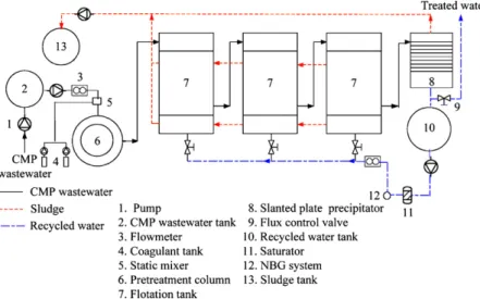
2.5. Pilot-scale study
A pilot-scale flotation unit including recycle system, with a total volume of 6 m3was installed in the existing wastewater treatment plant of DRAM manufacturing unit, Hsinchu Science-based industrial Park, Hsinchu, Taiwan. The schematic diagram of the designed flotation unit is shown inFig. 2. Initially, the raw CMP wastewater was mixed with activator and collector by a static mixer and fed into the pretreatment column using a feed pump at a designed flow rate. After pretreatment, the wastewater was treated in a series of flotation units with recycled water that was pressurized via nano-bubble generator and then flotation was allowed to proceed.
2.6. Experimental design and optimization
In order to assess the optimum operating conditions of the designed treatment system, the activator and collector concen-trations, hydraulic retention time (HRT) and recycle ratio were selected as the influencing factors (independent variables). On the other hand, turbidity, TS and dissolved silica removals were selected as the corresponding factors (dependent variables). The operating conditions were 30 and 60 mg/L as Al for activator concentration (PAC), 5 and 30 mg/L for collector concentration (NaOl), 1 and 2 h for HRT, 5 and 20% for recycle ratio. Totally, 16 trials were carried out (designed by 2k factorial design at
k = 4). The experimental observations are analyzed using the
analysis of variance (ANOVA). Based on the ANOVA, only two factors (p < 0.05) from the above four parameters were assessed for particle removal.
Table 2
Experimental design for optimum flotation experiments
Trial PAC (mg/L as Al) Recycle ratio (%)
1 32 3 2 88 3 3 32 17 4 88 17 5 20 10 6 100 10 7 60 0 8 60 20 9 60 10 10 60 10 11 60 10 12 60 10 13 60 10
The optimum conditions of the experiments were deter-mined by means of second-order central composite design (CCD) and response surface methodology (RSM). RSM is based on group of empirical techniques, used to find the relation-ship between a cluster of controlled experimental factors and measured responses according to one or more selected cri-teria [26,27]. The PAC concentration and recycle ratio were adjusted according to CCD. The experimental design is shown in Table 2. Finally, the comparison of cost-effective analysis between NBFT with coagulation and conventional coagulation processes adopted in DRAM manufacturing unit was investi-gated.
3. Results and discussion
3.1. Selection of effective activator/collector combination
As an initial stage of the investigation, 24 experiments were carried out using a laboratory-scale flotation reactor at differ-ent combinations of activator and collector. The initial pH of
the CMP wastewater was 9.4± 0.1 and the pH of the system
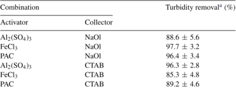
was not controlled throughout the experiment. The turbidity removal was selected to evaluate the treatment efficiency. The result shows that FeCl3/NaOl, PAC/NaOl and Al2(SO4)3/CTAB
combinations were more efficient in turbidity removal compared to other activator and collector combinations. The removal rates
were greater than 90% (Table 3). Compared with aluminum
sulphate species, polyaluminum sulphate was effective at less
Table 3
Turbidity removal for various combinations of activator and collector
Combination Turbidity removala(%)
Activator Collector Al2(SO4)3 NaOl 88.6± 5.6 FeCl3 NaOl 97.7± 3.2 PAC NaOl 96.4± 3.4 Al2(SO4)3 CTAB 96.3± 2.8 FeCl3 CTAB 85.3± 4.8 PAC CTAB 89.2± 4.6
aSamples were analyzed in triplicate.
coagulation/flocculation time, which can be attributed to the higher polymeric aluminum species and lower hydrophilic and more compact flocculated flocs of PACl coagulant[13]. Gener-ally, it has been established that higher streaming current values result from higher electric charge of the coagulant species[28]. Therefore, the increased basicity of the coagulant increases the enhanced charge neutralization ability. Due to this phenomenon, higher turbidity removal was observed with FeCl3/NaOl
com-bination. However, the issue of cost-effectiveness and quality of effluent (such as TS concentration, turbidity, effluent color, etc.) are considered for the selection of effective combination of activator/collector owing to the practical application. Among the three combinations, the reagent cost of the PAC/NaOl combination was one-third of Al2(SO4)3/CTAB combination.
On the other hand, FeCl3/NaOl combination has produced a
red-brown effluent due to ferrous ion. From the experimen-tal results, PAC/NaOl combination was selected as the best combination of activator/collector for NBFT with coagulation process.
3.2. Assessment of NBFT for CMP wastewater treatment
The effectiveness of NBFT against coagulation was assessed in a laboratory-scale reactor using the best combination of acti-vator/collector that identified in Section 3.1, i.e. PAC/NaOl. The percentage removal of turbidity was used to compare the efficiency of the processes. In NBFT, most of the turbidity was removed from wastewater within 40 min (from 350 to 7 NTU). However, maximum turbidity reduction of 99% was observed at the end of 50 min (Fig. 3). From the results, it was observed that turbidity removal efficiency in NBFT with coagulation process was 40% greater than the conventional coagulation process. It has been proven that collector ions adsorbed at the air–liquid interface during flotation enhanced the resistance of the bubble to rupture. Besides, it integrates the hydrophobicity of the solid particle and finally, provides an electrical potential to the bubble. As a result, it leads to long-range electrical interactions between gas bubbles and solid particles[29]. The production of finer bubbles using NBG and the increase in stability of the produced bubbles facilitates the NBFT more effective compared to coagulation process. Based
Fig. 3. Comparison of turbidity removal rate between the NBFT and coagulation process.
on the potential results, it could be proposed that NBFT with coagulation process has high potential for the treatment of CMP wastewater.
3.3. Optimization of NBFT with coagulation operating conditions
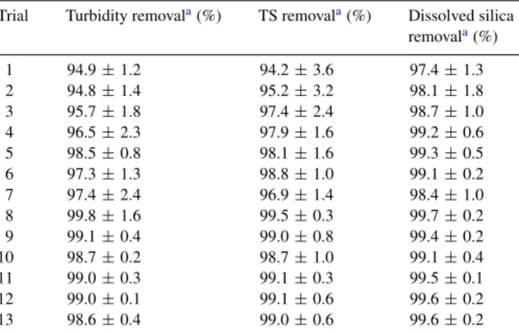
The parameters including pH, activator and collector con-centrations, hydraulic retention time (HRT), bubble size, bubble quantity (recycle ratio) and saturator pressure have consider-able influence in the application of NBFT. To cope with such a multi-parametric system, the factorial design was used to screen the significant factors. It was reported that the con-centration of PAC/polymer and wastewater pH are the most important factors, which mainly influence the turbidity removal in coagulation process[30]. Jar test and laboratory scale study inferred that more than 90% turbidity was attained when PAC concentration was controlled between 30 and 60 mg/L (as Al) and without pH adjustment of the system. During the labo-ratory and pilot-scale experiments, pH of the wastewater was decreased from 9.4 to around 6 at controlled PAC concentration (30–60 mg/L). The wastewater pH decreased steadily with cor-responding increase in PAC concentration and the floc formation was effective at a pH range of 5–7.5[1]. This finding reflects that additional pH control is not required when PAC is used as an activator in NBFT. The results of the 13 experiments formu-lated by CCD are shown in Table 4. It was observed that the removal efficiencies of turbidity, total solids and dissolved sil-ica in CMP wastewater were greater than 95%. It was reported that when pH of the system was less than 10, the addition of PAC was capable of enhancing the silica removal efficiency either by precipitation of Al(OH)3to adsorb the silica or
for-mation of the positive charge polynuclear hydroxoaluminium species to help complexation of slight negative charge species SiO2/H3SiO4− [31]. In addition, the decrease in pH value of
the system can be attributed to the formation of Al(OH)3, where
the removal of OH−ions from the system caused the reduction in the pH value. The design parameters such as activator and collector concentrations, HRT and recycle ratio were analyzed
Table 4
Turbidity, TS and dissolved silica removals in optimum flotation experiments Trial Turbidity removala(%) TS removala(%) Dissolved silica
removala(%) 1 94.9± 1.2 94.2± 3.6 97.4± 1.3 2 94.8± 1.4 95.2± 3.2 98.1± 1.8 3 95.7± 1.8 97.4± 2.4 98.7± 1.0 4 96.5± 2.3 97.9± 1.6 99.2± 0.6 5 98.5± 0.8 98.1± 1.6 99.3± 0.5 6 97.3± 1.3 98.8± 1.0 99.1± 0.2 7 97.4± 2.4 96.9± 1.4 98.4± 1.0 8 99.8± 1.6 99.5± 0.3 99.7± 0.2 9 99.1± 0.4 99.0± 0.8 99.4± 0.2 10 98.7± 0.2 98.7± 1.0 99.1± 0.4 11 99.0± 0.3 99.1± 0.3 99.5± 0.1 12 99.0± 0.1 99.1± 0.6 99.6± 0.2 13 98.6± 0.4 99.0± 0.6 99.6± 0.2
aSamples were analyzed in triplicate.
Fig. 4. Percentage removals of (a) turbidity, (b) total solids and (c) dissolved silica with respect to PAC concentration and recycle ratio in pilot-scale reactor study.
using ANOVA (results not shown). The contour lines of the response surfaces for the selected design parameters are shown inFig. 4(a–c). From the response surfaces and ANOVA (based on p-value < 0.05), it was observed that turbidity, total solids and dissolved silica removals were primarily depend on PAC concen-tration and recycle ratio. The maximum efficiency of the system was observed at a recycle ratio of 15–20% and PAC concentra-tion of 40–80 mg/L (as Al). From these observaconcentra-tions, it can be concluded that optimum conditions for the treatment of CMP wastewater were at 50–60 mg/L (as Al) of PAC concentration,
5–10 mg/L of NaOl concentration, 15–20% recycle ratio and 1 h HRT.
3.4. Particle–bubble interaction in flotation
The possible mechanism for the formation of aggregates of particles and bubbles in the NBFT is owing to (1) entrapment of preformed bubbles in large floc structures and (2) particle
collision and adhesion with preformed bubbles. Edzwald[14]
reported that flotation was not successful without the addition of coagulant and therefore, mechanism (1) is more important where large flocs are formed rapidly by the addition of PAC that provides positively charged polymeric Al species for particle destabilization via charge neutralization. Whereas, in mecha-nism (2), the collision between bubble and particle is enhanced by the addition of collector. The performance of a flotation sys-tem can be explained by air to solid (A/S) ratio as in Eq. (1), which affects particle–bubble collision, particle separation and removal[32]:
A S =
1.3Sa(fP − 1)R
X (1)
where Sais the air solubility, 18.7 mL/L at 20◦C; f is the air
satu-ration ratio at pressure P (0.8); P is the pressure (gauge pressure +1), atm; R is the recycle ratio; X is the solid content, mg/L. In practical application, the recycle ratio (R) is used as a surro-gate measure of the air bubble supplied for a constant saturator pressure. From Eq.(1), A/S ratio required for the corresponding optimum recycle ratio (15–20%) was estimated as 0.002–0.003. It is roughly one-third of the minimum value recommended by Chung and Kim[32]; however, the estimated A/S ratio is in good agreement with Ross et al.[33]. It indicates that the flocculated particles in the CMP wastewater could be removed effectively by the present system (NBFT) at a much lower A/S ratio. This observation can be attributed to the high rate of collision between the large number of smaller bubbles and particles.
3.5. Assessment of NBFT with coagulation and conventional coagulation processes
The performance of NBFT with coagulation and conventional coagulation process used at present in the DRAM manufac-turing unit are compared in Table 5. Although the turbidity, TS and dissolved silica removals were more than 95% in both NBFT with coagulation and conventional coagulation, the efflu-ent quality was better in NBFT with coagulation. Chen et al.
[31]investigated the removal of silica from wastewater with high magnesium by coagulation using PAC. They observed that PAC was capable of enhancing the silica removal to greater than 80%, however the percentage silica removal was reduced for pH val-ues higher than 11. Huang and Liu[12]have studied the flotation of fluoride using SDS, NaOl and n-dodecylammonium chloride (DAC) as frother and collector. Their results show that SDS was best with 98% calcium fluoride (CaF2) removal, followed by
NaOl (64%) and DAC (11%). Besides, it was observed from the literatures that flotation efficiency increases with increas-ing concentration of collector/activators[11,34,35]. However,
Table 5
Comparison of operating parameters and performance between NBFT and coagulation
Operating conditions NBFT Coagulation process
Capacity (m3/h) 5 20
Running time (h) 2 6
Recycle ratio (%) 10 –
Activator dosage (L/m3h) 0.7 (PAC) 2.0 (FSC-855) Collector dosage (g/m3h) 5.0 (NaOl) 36.0 (FA-40)
pH control 4–6 8
Influent turbidity (NTU) 523 523
Influent TS (mg/L) 8850 8850
Influent dissolved silica (mg/L) 4440 4440 Performance
Effluent turbidity (NTU) 1 9
Turbidity removal (%) 99.8 98.3
Effluent TS (mg/L) 80 320
TS removal (%) 99.1 96.4
Effluent dissolved silica (mg/L) 19 22
Dissolved silica removal (%) 99.6 99.5
Table 6
Comparison of cost-effectiveness between NBFT and coagulation
Item NBFT approach Coagulation process
Chemicals costa 0.30 1.20
Power costa 0.15 0.18
Maintenance costa 0.15 0.20
Personnel expensea 0.15 0.15
Total operating costa 0.75 1.73
a Unit: USD/m3CMP wastewater.
the activator and collector dosage required for the treatment of 1 m3of CMP wastewater by conventional coagulation process are three and seven times, respectively, higher than that required for NBFT with coagulation process. Besides, pH adjustment is essential in coagulation process when using FSC-855 and FA-40 (used presently in DRAM manufacturing unit, Science based industrial park, Hsinchu, Taiwan) as coagulant and poly-mer, respectively. Whereas, no pH control is required when PAC is used as an activator in NBFT with coagulation process. As a whole, conventional coagulation process requires four times higher chemical cost compared to NBFT with coagulation pro-cess (Table 6). Moreover, the total operating cost required for conventional coagulation process is around US$ 1.73 m−3 of CMP wastewater. Whereas, it can be reduced to US$ 0.75 m−3of CMP wastewater, by the application of NBFT with coagulation process. Hence, conventional coagulation can be replaced by NBFT with coagulation process for the cost-effective treatment of CMP wastewater.
4. Conclusions
The cost-effective treatment of CMP wastewater was inves-tigated using laboratory and pilot-scale flotation reactors. The NBFT with coagulation process can be operated effectively at a PAC concentration of 50–60 mg/L (as Al), NaOl concentra-tion of 5–10 mg/L, and recycle ratio of 10–20% with 1 h HRT. The treatment of CMP wastewater can be carried out
with-out any pH adjustment when PAC was used as an activator. The operating as well as chemical costs required for NBFT with coagulation process was much lesser compared to conven-tional coagulation process employed currently by most of the semiconductor-manufacturing units in Taiwan. However, addi-tional trials in the optimal operating condition are necessary before the field scale application of the developed NBFT with coagulation process.
Acknowledgement
The authors are grateful to the Environmental Protection Administration, Taiwan, ROC (under the grants EPA-92-E1U4-04-003 and EPA-93-U1U4-EPA-92-E1U4-04-003) for the financial support of this work.
References
[1] S.H. Lin, C.R. Yang, Chemical and physical treatments of chemical mechanical polishing wastewater from semiconductor fabrication, J. Haz-ard. Mater. 108 (2004) 103–109.
[2] G.C.C. Yang, T.Y. Yang, Reclamation of high quality water from treat-ing CMP wastewater by a novel crossflow electrofiltration/electrodialysis process, J. Membr. Sci. 233 (2004) 151–159.
[3] C.Y. Hu, S.L. Lo, C.M. Li, W.H. Kuan, Treating chemical mechanical polishing (CMP) wastewater by electro-coagulation-flotation process with surfactant, J. Hazard. Mater. 120 (2005) 15–20.
[4] G.C.C. Yang, T.Y. Yang, S.H. Tsai, Crossflow electro-microfiltration of oxide-CMP wastewater, Water Res. 37 (2003) 785–792.
[5] C.L. Lai, S.H. Lin, Electrocoagulation of chemical mechanical polish-ing (CMP) wastewater from semiconductor fabrication, Chem. Eng. J. 95 (2003) 205–211.
[6] C.L. Lai, S.H. Lin, Treatment of chemical mechanical polishing wastewater by electrocoagulation: system performances and sludge settling character-istics, Chemosphere 54 (2004) 235–242.
[7] Y.F. Chan, Recovery of the nanometric particles of silicon oxide (SiO2)
by column pressurized flotation technology, MS thesis, Department of Resources Engineering, National Cheng-Kung University, Taiwan, 2000. [8] B.M. Belongia, P.D. Haworth, J.C. Baygents, S. Raghvan, Treatment of
alu-mina and silica chemical mechanical polishing waste by electrodecantation and electrocoagulation, J. Electrochem. Soc. 146 (1999) 4124–4130. [9] J.H. Golden, R. Small, L. Pagan, C. Shang, S. Raghvan, Evaluating and
treating CMP wastewater, Semiconductor Int. 23 (2000) 92–103. [10] J. Rubio, M.L. Souza, R.W. Smith, Overview of flotation as a wastewater
treatment technique, Miner. Eng. 15 (2002) 139–155.
[11] A.I. Zouboulis, K.A. Matis, Removal of cadmium from dilute solution by flotation, Water Sci. Technol. 31 (1995) 315–326.
[12] C.J. Huang, J.C. Liu, Precipitation flotation of fluoride-containing wastew-ater from semi-conductor manufacture, Wwastew-ater Res. 33 (1999) 3403–3412. [13] Y. Wang, J. Guo, H. Tang, Pilot testing of dissolved air flotation (DAF) in a highly effective coagulation–flocculation integrated (FRD) system, J. Environ. Sci. Health A 37 (1) (2002) 95–111.
[14] J.K. Edzwald, Principles and applications of dissolved air flotation, Water Sci. Technol. 31 (1995) 1–23.
[15] A.A. Al-Shamrani, A. James, H. Xiao, Separation of oil from water by dissolved air flotation, Colloid Surf. A: Physicochem. Eng. Aspect 209 (2002) 15–26.
[16] K. Fakushi, N. Tambo, Y. Matsui, A kinetic model for dissolved air flotation in water and wastewater treatment, Water Sci. Technol. 31 (1995) 37–47. [17] T.C. Chuang, C.J. Huang, J.C. Liu, Treatment of semiconductor wastewater
by dissolved air flotation, J. Environ. Eng. 128 (2002) 974–980. [18] T. Takghashi, T. Miyahara, H. Mochizuki, Fundamental study of bubble
formation in dissolved air pressure flotation, J. Chem. Eng. Jpn. 12 (1979) 275–280.
[19] T. Zabel, Flotation in water treatment. In: K.J. Ives (Ed.), The Scientific Basis of Flotation, NATO ASI Series, Martinas Nijhoff, Boston, USA, pp. 349–377.
[20] S.E. De Rijik, J.H. Vander Graaf, J.G. Blanken, Bubble size in flotation thickening, Water Res. 28 (1994) 465–473.
[21] P.S. Wollen, Reusing tertiary effluent after treatment with a DAF and sand-filter system, Paper Technol. 38 (1994) 18–20.
[22] M.T. Valade, J.K. Edzwald, J.E. Tobiason, J. Dahtquist, T. Hedberg, T. Amato, Pretreatment effects on particle removal by flotation and filtration, J. AWWA 88 (12) (1996) 35–47.
[23] F. Rigas, P. Panteleos, C. Laoudis, Central composite design in a refinery’s wastewater treatment by air flotation, Global Nest 2 (2000) 235–253. [24] Standard Methods for the Examination of Water and Wastewater, 19th ed.,
APHA, AWWA and WEF, Washington, DC, USA, 2005.
[25] W. Den, C. Huang, Electrocoagulation for removal of silica nano-particles from chemical-mechanical-planarization wastewater, Colloid Surf. A: Physicochem. Eng. Aspects 254 (2005) 81–89.
[26] E. Bayraktar, Response surface optimization of the separation of Dl-tryptophan using an emulsion liquid membrane, Process Biochem. 37 (2001) 169–175.
[27] M.Y. Can, Y. Kaya, O.F. Algur, Response surface optimization of the removal of nickel from aqueous solution by cone biomass of Pinus
sylvestris, Bioresour. Technol. 97 (2006) 1761–1765.
[28] Z. Luan, J. Qu, H. Tang, Species stability and electro-kinetic characteris-tics of polyaluminium chloride in coagulation and flocculation processes, Environ. Chem. (China) 16 (6) (1997) 506–514.
[29] R. Perea-Carpio, F. Gonzalez-Caballeero, J.M. Bruque, On the interactions at interfaces in fluorite flotation, Int. J. Miner. Process. 23 (1988)229– 240.
[30] S.H. Lin, C.D. Kiang, Combined physical, chemical and biological treat-ments of wastewater containing organics from a semiconductor plant, J. Hazard. Mater. B97 (2003) 159–171.
[31] S. Chen, T. Chang, C. Lin, Silica pretreatment for a RO brackish water source with high magnesium, Water Sci. Technol. 6 (4) (2006) 179–187. [32] T.H. Chung, D.Y. Kim, Significant of pressure and recirculation in sludge
thickening by dissolved air flotation, Water Sci. Technol. 36 (1997) 223–230.
[33] C.C. Ross, B.M. Smith, G.E. Valentine, Rethinking dissolved air flotation (DAF) design for industrial pretreatment, in: WEF and Purdue University Industrial Wastes Technical Conference, 2000.
[34] M.M. Koutlemani, P. Mavros, A.I. Zouboulis, K.A. Matis, Recovery of Co2+ions from aqueous solution by froth flotation, Sep. Sci. Technol. 29
(1994) 867–886.
[35] P. Sanciolo, I.H. Harding, D.E. Mainwaring, The removal of chromium, nickel and zinc from electroplating wastewater by adsorbing colloid flota-tion with a sodium dodecylsulfate/dodecanoic acid mixture, Sep. Sci. Technol. 27 (1992) 375–388.