REVIEW
On Liquid-Phase Deposition of Silicon Dioxide by
Boric Acid Addition
Peng-Heng Chang, Chen-Tang Huang,b and un-Shown Shie6
°Instjtute of Materials Science and Engineering and binstitute of Electro-optical Engineering, National Chiao Thug University, Hisinchu, Taiwan
ABSTRACT
The current status of liquid-phase deposition (LPD) of Si02 by adding boric acid (H3B03) to a hydrofluosilicic acid (H2SiF6) is reviewed and compared with some new results from the authors' laboratory Large discrepancies exist in the literature concerning the effects of various processing parameters on deposition rate. We have shown that much confu-sion arises from the misconception of using on 5i03 additive to "saturate" and usng water to "dilute" the growth solu-tion. In this paper the role of 1120 as a reagent and the detrimental effect of an 5i02 additive as seeds for depleting the nutrient in the growth solution if added after the H30 addition are emphasized. Despite the variations between different investigators, the following characteristics of the LPD process are in general agreement: (i) the deposition process is sur-face controlled, (ii) the deposition rate depends approximately linearly on temperature, (iii) the deposition rate is constant (independent of time) over a wide range of experimental conditions, and (iv) the deposition rate increases with increas-ing boric acid concentration.
The recently developed liquid-phase deposition (LPD) process ailows the selective growth of thin 5i03 films on
suitable substrates at very low temperatures (20 to 50°C).'-2' The growth is typically conducted in a supersaturated hydrofluosilicic acid (H2SiF6) solution. A simplified model
due to Nagayama et al.1 shows that the deposition is the result of the reaction between H2SiF6 and water
H2SiF6 + 21120 fl 5i02 + 611F [1]
According to this reaction, more 5i02 may be formed if the concentration of H2SiF8 or 1120 is increased, or the con-centration of HF is reduced. Experimentally, three differ-ent teclmiques have been successfully developed based on the above reaction to bring about the 5i02 deposition from an H2SiF6 solution simply by adding either boric acid (H3B03)''5 or Al18-21, or water14'1 to the growth solution. In
the first two cases, boric acid or aluminum reacts with HF
to form BF 22 or A1F3, 23 respectively. These reactions con-sume hydrofluoric acid in the growth solution thus pro-moting reaction 1 to the right according to Le Chatelier's principle so that more 5i03 is formed. The addition of water to the growth solution also drives reaction 1 to the right thus favoring the 5i02 deposition.
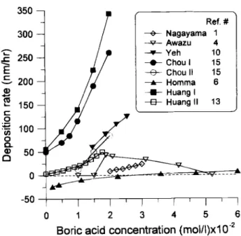
By far, the addition of boric acid to the H2SiF8 solution is the most popular technique in LPD-Si02 deposition. However, in an attempt to compare the results obtained by different groups of the 5i02 deposition rate as a function of boric acid addition, a very large variation is noted as revealed in Fig. 1. The disagreement is so large that under certain conditions it exceeds two orders of magrntude (for
instance in Fig. 1 at the boric acid concentration of 2 )< 102
mol/liter the deposition rate varies from 0. to 260 nm). In one case (the Homma results, the [(A) curve in Fig. lithe addition of boric acid below 2.5 X 10² mol/liter even resulted in the etching (negative deposition rate) instead of deposition of 5i02. Table I summarizes the relevant exper-imental conditions used by each investigator whose data are included in Fig. 1. It shows that significant variation exists in the details of LPD processing employed by dif-ferent groups. In this paper the current status of the LPD
process is reviewed, some of the most recent results from the authors' laboratory are presented to clarify some of the confusing issues and to explain the large discrepancy revealed in Fig. 1. The emphasis of the paper is on the technique of growing S103 by the addition of boric acid to N2SiF6 solution, but most of the discussions are equally applicable to other techniques of the LPD process. The organization of the following discussion is such that the
important LPD processing parameters are reviewed
sequentially and individually with special reference to Fig. 1 and Table I.
0 -50 Ref. # —t--- Nagayama 1 —— Awazu 4 —'-- Yeh 10 —e—Choul 15 —8-- Chou II 15 —a-— Homma 6 —t— Huang I —B— Huang II 13
Fig. 1. The effect of boric acid concentration on the deposition rate of Si03 as reported by various investigators.
350 300 250 200 150 100 50 I.--C C a, 4.' Ct C .6-i C,,
0
a
a,C
0 1 2 3 4 5 6Boric acid concentration (mol/t)x102
-ED s O10 CA C CM C D "s I Id I ARCS o 00 X' I ? ' CID 1D a: 100 10 Lo 0 Cm x 'e Cn u o 1a o 0 rd Cl t o 0o 0
3
cs o s Cs s il M Cn C C U a a) C a)"I-' 0 .~0 .0 .~0- 0 C ,~N
eo o *~ CD CD 'n 10 0 Cl o 0 ° 6 6 02 1 1) o 0 0DC l I C l -o, - 0 o 6026. : 0 i C 0> C 1 co I -! - - -1 -! j -j x 0 0 0D :3 j- - -I -I I 0 0 e CO CI
(2 (C~ MCC lC " NC l d Cl Cl Cl -C Z D I I2 M to ADCCThe Starting H2SiF6Solution
Except for Awazu et al.,4 who prepared his own H2SiF6 solution by dissolving silica gel in an HF solution, other investigators used commercial grade H2SiF6 solutions. As shown in column 2 of Table I, the concentration of H2SiF6 in the starting solution varies from 2 to 4 M. An SiO2 addi-tive was used by every group to react with the free HF in the starting solution in order to "saturate" the solution. The choice of the additive may be either silica gel or sili-cic acid (column 3), the stirring time for the dissolution of SiO2 additives varies from 3 to 17 h (column 4), and the dissolution temperature differs from 23 to 35°C (column 5). Generally silicic acid dissolves much faster than silica gel. The difference in the dissolution rate compounded with the variation in dissolution temperature and in stirring time could lead to significant variation in the actual con-centration of H2SiF6 even if the same concentration is reported, thus rendering scattered results on the reported deposition rate even under the same growth conditions. Kawahara et al.6 has shown that a very low low dissolu-tion temperature (-3°C) coupled with a high growth tem-perature (60°C) may be utilized to effect a very high growth rate. This result is consistent with the fact that the dissolution of SiO2 in HF is an exothermic reaction2 4 so that the dissolution of SiO2 additives is enhanced at a lower temperature. A large supersaturation is induced when the solution saturated at a lower temperature is brought up to 60°C for growth, therefore a high growth rate results.
The erratic behavior of Awazu's data in comparison with others in Fig. 1 casts serious doubt on the reported H2SiF6 concentration of his self-made solution. Since this set of data is so different from others, it is considered rather unreliable and will be excluded from further discussion.
The Growth Solution
The growth solution for LPD-SiO2 deposition is usually prepared from the starting solution by further modifying its chemical content. One of the most important parame-ters concerning the growth solution is its H2SiF6 concen-tration. Experimentally two different routes may be cho-sen depending on the sequence of adding an SiO2additive and water. Some investigators added the SiO2 additive prior to diluting with water (route I) while others "dilut-ed" their H2SiF6solution with water prior to the addition of an SiO2 additive (route II). The reported molar concen-tration of H2SiF6 in the growth solution is generally calcu-lated from the volume change due to the water addition, and in so doing the calculated H2SiF6 concentration is always the same irrespective of the sequence of SiO2 and water addition. Interestingly, the deposition rate has been found to vary dramatically with the sequence of additions and in a controlled experiment Chou and Lee5have shown that the deposition rate for growth solutions prepared by route I (Chou I in Fig. 1) is much greater than those pre-pared by route II (Chou II in Fig. 1). A model was proposed by Chou et al." for explaining the variation of deposition rate in terms of the difference in the amount of intermedi-ate species formed by the two different routes. However, it is also possible to interpret the results in a different way as follows: it should be emphasized that according to reac-tion 1 water is a reagent and not simply a solvent, and when added to the starting solution it is expected to react with H2SiF6 to form SiO2 and HE In this context it is very misleading to call the addition of water to H2SiF6 solution "dilution" as in diluting salty water with HO. It casts doubt on the conventional way of calculating the H2SiF6 concentration by the volume change due to water addition because the reaction between the two species, H,2SiF6 and H2,O, is totally ignored. Although reaction 1 indicates that adding HO to H2SiF6 would cause SiO2 to form, usually this does not happen spontaneously unless a proper sub-strate (typically one with SiO2 surface) is immersed in the solution and then the deposition occurs on the SiO2 sur-face only It appears therefore that the SiO2 sursur-face lowers
to b cd to co C CC NC) Lo C Cs Cs Cs Cs Cis.3 C 3 0 0 0 0. 0 co CZ c co c ; 0 0 0 0 0 zC2 Cl As4C U 3C M 3C 3 co, Cl
0
0D CDI
'Ag
._a 0 I 0 t. E :_ C C 0 E x6 C e-C -0 0 .0 a s. ocsE 0 0 O X Cso-= o E .0 sO b > W o.5 Cs. t~ 4.' 4> TC s t 4.> 0W 0EE C's to01146 J. Electrochem. Soc., Vol. 144, No. 3, March 1997 The Electrochemical Society, Inc. the activation barrier for Si02 precipitation from an LPD
growth solution. Now consider route II as described earli-er, when 1120 is added first to the H2SiF6 solution, a reac-tion between the two species is about to occur, but without
a proper substrate the solution is maintained at a
metastable state without deposition. The subsequently added Sb2 additives actually serve as the needed sub-strates that provide an enormously large Si02 surface for Si02 to deposit from the solution. In this regard the growth solution is in reality being depleted of Si02 instead of being saturated as previously mistakenly suggested by most investigators. On the other hand, when route I is fol-lowed, the first SiO2 additive would react with any free HF in the starting solution to bring the H2SiF5 concentration to its saturation level. The 1120 added subsequently tends to react with H2SiF6, but without a proper substrate the solution is in a metastable condition with its ability to deposit SiO2 completely preserved. Later in the actual growth run a much higher deposition rate is observed with solutions prepared by route I than route II. It is worth
not-ing that in Fig. 1 the Nagayama et at. and Homma at at. solutions were prepared by route II and their observed
deposition rates are much lower than the others', as
expected from the forgoing argument. It is also highly
probable that the solution in Homma's study was so
depleted with the Si02 nutrient such that etching of the substrate resulted.
The concentration of H2SiF5 in the growth solution is bound to affect the deposition rate. According to reaction 1 a larger deposition rate is expected of a solution with a higher starting H2SiF5 concentration if other parameters remain constant, but the exact dependence is yet to be established.
TheBoric Acid Addition
Despite
the large variation in the deposition rate
observed by various groups, all the curves in Fig. 1 (except Awazu et at.) show a positive dependence of deposition rate on boric acid concentration, although the magnitude of the dependence differs significantly due to the variation in other experimental parameters. The data of Chou I [(•) curve] and Huang I [(•)curve] in Fig. 1 show the largest dependence on boric acid concentration. These two stud-ies have at least several experimental parameters common to the other studies, except for the deposition temperature of 50°C which is not only unique to them but also higher than the temperature employed by others. It is therefore likely that dependence of the deposition rate on boric acid concentration is enhanced by increasing temperature. It is worth noting that the only difference in the experimental conditions between Chou I and Huang I is in the tempera-ture for dissolving an Si02 additive (column S of Table I), the former used 30°C while the latter used 25°C. As dis-cussed earlier since a lower dissolution temperature gives rise to higher H2SiF6 concentration in the saturation solu-tion, it is therefore not too surprising to see that these two sets of data agree reasonably well and that Huang I shows a slightly higher deposition rate than Chou I. The high deposition rate observed for these two cases can be attrib-uted to two factors: high deposition temperature and pre-paring the growth solution by route 1.
Two issues are of primary concern considering the addi-tion of boric acid, namely, its quantity and concentraaddi-tion when added to the growth solution. Commercial boric acid is generally in powder form, for LPD application it is always used in the form of an aqueous solution. Column 8 of Table I lists the stock boric acid concentration used by each investigator. As can be seen, most investigators used 0.1 M boric acid stock solution; a notable exception is Awazu at at.4 who used a 0.518 M solution. The actual boric acid concentration in the growth solution is,
howev-er, different from the concentration of the stock solution because it must be corrected for the volume of the H2SiF6 solution into which the boric acid solution is added. The corrected boric acid concentrations for each investigator are listed in column 9 of Table I. Reciprocally, the H2SiF6
concentration in the growth solution is also affected by the boric acid addition because the total volume is changed. This point, which has been overlooked before by almost every group, causes a large uncertainty in the reported H2SiF6 concentrations especially when using stock boric acid solutions of different concentrations. Under such cir-cumstances the water content in the added boric acid solu-tion is varied such that the actual H2SiF, concentrasolu-tion varies accordingly.
Another important observation is that Si02 deposition does not happen spontaneously after the addition of boric acid if its concentration is below a certain level; a proper substrate is required for activating the deposition process. This phenomenon is quite similar to the effect of water addition described earlier. On the other hand, it is also observed that spontaneous Si02 deposition in the form of feathery powders suspended in the growth solution could occur with no need of a substrate if a larger amount of boric acid is added to the H2SiF6 solution. At the present time the cutoff boric acid concentration where sponta-neous deposition sets in is yet to be determined, but our experience shows that it is greater than 0.02 mol/liter in the solution used in our earlier study.'3 Nevertheless once a proper substrate is introduced, a growth solution with boric acid addition always has a higher deposition rate than without the boric acid addition.'5
Other minor issues such as the mixing time after boric acid addition and the way of adding boric acid (batch or continuous) are also at variance among different groups. In our view, however these points are only of secondary importance.
GrowthTemperature
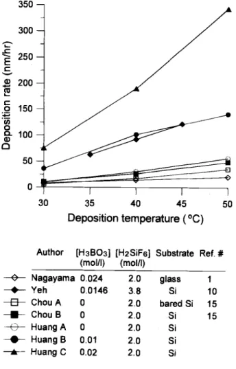
Thedeposition rate of LPD-SiO2 is affected by the tem-perature, and Fig. 2 compares the literature data with some of our unpublished results. The comparison between
different curves in this figure is not straightforward
because other experimental conditions were not kept con-stant, but even so the trend in Fig. 2 demonstrates clearly
that for each and every curve the deposition rate is
increased with increasing temperature. The difference among the curves is evidently due to other parameters such as the concentrations of hydrofluosilicic acid and boric acid, substrates, etc. The divergence of the curves in Fig. 2 decreases rapidly as the temperature is decreased indicating that the effects of other processing factors become less significant at lower temperatures. Figure 2 also shows that the temperature dependence of the depo-sition rate is fairly linear between 30 to 50°C. A higher growth temperature is advantageous for faster SiO2 depo-sition but the increased variability in depodepo-sition rate is a concern from the process point of view. Another drawback of higher temperature growth is the significant loss of
growth solution due to evaporation which is usually
insignificant below 30°C but becomes evident at 5 0°C. It is
not clear exactly what is being evaporated as yet, but the fact that the condensation of the evaporating vapor on the top of the reactor always results in the formation of pow-dery SiO2 implying a rather complex vapor chemistry. The evaporation loss certainly changes the concentration of the growth solution thus affecting the deposition rate. For this reason the higher temperature data in Fig. 1 and 2 should be viewed with some caution. Nonetheless, the
large variation observed in Fig. 1 cannot be totally
ascribed to the temperature effect because, by comparing
Yeh at at. and Homme at at. data in Fig. 1, one may see that
even at the same temperature (3 5°C) the deposition rate still varies by about two orders of magnitude, which is much greater than that would be expected from the tem-perature effect depicted in Fig. 2.
Subsfrate
LPD is highly selective; Si02 deposition occurs on the surface of thermal Si02 chemically vapor deposited (CVD) Si02, native oxide on silicon, or polysilicon, but not on the surface of photoresist and sputtered tungsten.7"° The
results on bare silicon are somewhat controversial, Chou13
reported a small amount of growth but the overwhelming majority of published results reported no deposition.7 The deposition of LPD-Si03 on plastic is also possible if the substrate surface is pretreated by a silane coupling agent with an amino functional group such as
'y-aminopropyltri-ethoxysilane.19 The growth rate is not affected by the
phys-ical arrangement of the substrate in the growth solution, it may be either faceup, facedown, or face sideways. As pointed out earlier that a proper substrate is absolutely essential to the growth of LPD-Si02, so a surface-con-trolled growth mechanism is implied. Two models have recently been proposed for explaining the selective
depo-sition of LPD.7'13 The common features of these models are the necessity of Si—OH bonds on the substrate surface and
the formation of intermediate species in the growth solu-tion; the deposition of LPD-SiO3 is brought about by the reaction of the intermediate species with Si—OH bonds on the substrate surface. Two different intermediate species,
SiFm(OH)4m (m < 4)7 and [SiF6 SiF4]2, 17 have been sug-gested but confirmation of this is yet to come. We have performed the following simple experiment to confirm the surface-controlled characteristics of LPD process:
LPD-SiO3 deposition was conducted at 40°C on oxidized Si
sub-strates with the dimension of 4.5 x1.7cm (sample A) and 4.5 X 3.4 cm (sample B) in a 1 M H2SiF6 solution diluted
from a 3.09 M H2SiF6 solution by water addition. Separate batch but equal volume (92.7 cm3) of growth solutions were employed for the two samples and the growth rate was found to be 41.1 and 42.7 nm/h, respectively, for sam-ple A and B. Using a third samsam-ple (samsam-ple C) of the same size as sample A to grow SiO2 under the same condition but with a solution of twice the volume (185.4 cm3), the
2.0 glass 1 0.0146 3.8 Si 10 0 2.0 bared Si 15 o 2.0 Si 15 0 2.0 Si 0.01 2.0 Si 0.02 2.0 Si
Fig. 2. The effect of growth temperature on the deposition rate of 5i02 as reported by various investigators.
growth rate was found to be 43.7 nm/h. The difference in the growth rate among these three samples is within 5% and thus is considered insignificant experimentally, so these results indicate that the deposition rate is practical-ly independent of the volume of the growth solution and of the surface area of the substrate. It is reasonable to expect that the absolute quantity of SiO3 available for growth in a growth solution is doubled when the solution volume is doubled. If the growth were due to a volume-controlled mechanism, the growth rate of sample C would have been twice that of sample A because of the doubling in solution volume. On the other hand, if the growth of LPD-Si03 requires Si—OH bonds on the substrate surface then a
con-stant growth rate is expected irrespective of the volume of the growth solution, as indeed observed experimentally. Additionally, it may be pointed out in comparing samples A and B, the SiO3 content available for deposition in the growth solution is the same because growth solutions of equal volume were used, the fact that sample B though
having twice the surface area but showing the same
growth rate as sample A indicates that twice the amount of SiO3 is deposited on sample B than sample A. This is only possible if the deposition process is dictated by the surface of the substrate; the number of Si—OH bonds per unit area is constant independent of the substrate surface area, so a growth rate expressed in terms of the increase in thickness per unit time is expected to be constant if the growth is surface controlled.
ReactorDesign
Theprimary concern of the reactor design for LPD-SiO3 deposition is the ease of handling. The reactor must also be able to withstand the attack of HF acid under moderate temperature. Evaporation loss is an important issue in designing a new reactor and the key point is to keep the exposed surface of the growth solution to a minimum. Part of the scattering shown in Fig. 1 may come from the vari-ation in evaporvari-ation loss due to the difference in reactor design. Mechanical or magnetic stirring devices are often used in LPD reactors to improve mixing thus enhancing the uniformity of deposition. Some investigators9"2'20 cir-culated the growth solution through a filtering device in order to remove any Si03 precipitates suspended in the solution. Our experience shows that the suspended SiO2 precipitates form spontaneously only when the boric acid concentration is higher than a certain level (about 20 x
10'
mol/liter for the present study, depending ontemper-ature and H,SiF, concentration),13 below which the growth
solution always remains clear indefinitely. The filtering out of the SiO, precipitates inevitably causes a shift in the equilibrium of the chemical species in reaction 1 resulting in significant change in the subsequent deposition kinetics relative to an unfiltered growth solution. In view of the foregoing discussions, the results in Fig. 1 corresponding to the higher boric acid concentration should be viewed and compared with greater caution. It is recommended that the boric acid addition should be kept below 2.0 x iO mol/liter for future fundamental studies of the LPD kinetics in order to avoid the SiO, precipitation in the growth solution.
GrowthRate
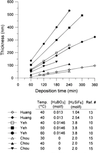
The reported growth rate is typically calculated by dividing measured film thickness by the growth time, so it represents a global average growth rate instead of the (instantaneous) true growth rate. However, it is found experimentally that in most cases the grown SiO, film thickness varies linearly with deposition time, as clearly demonstrated in Fig. 3. Because of the variations in other processing parameters, the data in Fig. 3 show very large scattering, but the linear dependence is generally fol-lowed. A small negative deviation from a linear
depen-dence is observed in one case [(•) data in Fig. 31; this
devi-ation is not unexpected because, in principle, the growth rate can never be sustained at the same rate as the deposi-tion is prolonged and the nutrient in the growth soludeposi-tion is 350 300 50 0 250 W 200 CD 150
a 100
0
-0-
-.-
-a-C-.-
-A-30 35 40 45 50 Deposition temperature (°C)Author [H3B03] [H2SiF6] Substrate Ref. #
(mol/l) (mol/l) Nagayama 0.024 Yeh Chou A Chou B Huang A Huang B Huang C
1148 J. Electrochem. Soc., Vol. 144, No. 3, March 1997 The Electrochemical Society, Inc. Temp. [H3B03] [H2S1F6] Ref. # (°C) (mol/l) (molIl) —e--— Huang 40 0.013 1.04 13 2.54 13 3.8 10 3.8 10 3.8 10 30 0 2.0 15 40 0 2.0 15 50 0 2.0 15
Fig. 3. The dependence of Si02 film thickness on the deposition time as reported by various investigators.
beingdepleted. For IC applications the required Si02 film thickness is such that the deposition time rarely exceeds several hours so that the growth is typically within the lin-ear regime. Under such conditions the global growth rate is the same as the true growth rate.
Another interesting observation of Fig. 3 is that,
although not drawn, all the curves seem to converge rea-sonably well to the origin. This means that there is no delay of deposition once the substrate is immersed in the growth solution. On the other hand, Chou and Lee'5 have claimed that there is a delay of deposition and the delay time is decreased from 25.4 to 15.3 mm as the deposition temperature is increased from 30 to 50°C. We feel that there is not enough data at the present time to make any meaningful evaluation of the growth behavior at the early stage of LPD-Si02 deposition (let alone interpret the phys-ical significance of a negative delay time). More work is definitely needed to understand the initial stage of LPD-SiO, growth.
FilmProperties
Visualinspection shows that the surface quality of LPD-Si02 films, as shown in Fig. 4a, is comparable to the oxide films prepared by other techniques, such as thermal oxi-dation and CVD deposition. Only at high rate of deposi-tion (for example, in a high temperature growth run with large amount of boric acid addition) do the films become cloudy, as shown in Fig. 4b, because of the presence of powdery Si02 precipitates in the growth solution. This problem may be alleviated by filtering out the suspended precipitates continuously as several investigators did in their studies.9"2'2° The residual stress of an as-deposited fim is tensile38 and its magnitude increases somewhat upon annealing at 400°C due to the reduction of water components in the films,8 but the residual stress is changed
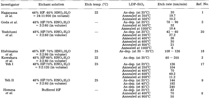
to the compressive state if the films are annealed at 900°C due to densification.8 The refractive index of the as-deposited LPD-SiO2 films is around 1.43,2,8,9,20 and it decreases slightly with increasing deposition rate9"°"3 or increasing postannealing temperature.'7 The planar etch rate in a buffered HF solution is found to be slightly high-er for the as-deposited LPD-Si02 films than for the thhigh-er- ther-mal or CVD oxides.13"8 The etch rate increases with increasing deposition rate,9"2"7 postannealing can result in
a significant (>50%) decrease in the etch rate due to the densification of the film."28"7'2° Table II summarizes the etch rate data from various studies. Despite the large vari-ation in the deposition rate, the etch rate of LPD-Si02 generally falls within a much narrower range of 15 to 83 nm/mm. The LPD-Si02 have better electrical proper-ties than CVD-Si02 films,8'9 the leakage current density is
14 nA/cm2 at 5 MV/cm," the dielectric breakdown
strength is >6.3 MV/cm,0'89"4 and the dielectric constant is <3.9 at 1 MHz.0'8'9" Because of the use of fluorine-con-E C (I) (I) U) C
0
-C I— 600 500 400 300 200 100 0Si02
surface
0 60 120 180 240 300 360 Deposition time (mm)(a)
-.-
-a-
-U-
-.-
-A-40 0.013 40 0,0146 50 0.0146 60 0.0146 Huang Yeh Yeh Yeh Chou Chou Chou(b)
Fig. 4. SEM microsfructures of LPD-Si02 films on Si substrates. The
boric acid concentration in the growth solution was (a) 0.01 and (b) 0.022 molt liter at 40°C, respectively.
Table II. Etching conditions employed by various investigators.
Investigator Etchant solution Etch temp. (°C) LDP-SiO, Etch rate (mn/mm) Ref. No.
22 1 As-dep. (at 35°C) 60 205 As-dep. (at 35°C) Annealed at 250°C 126104 17 Annealed at 400°C 70 Annealed at 600°C 49.2 Annealed at 800°C 11.2 As-dep. (at 35°C) As-dep. (at 40°C) As-dep. (at 45°C) 144 192 240 9 As-dep. (at 35°C) Annealed at 400°C 8370 8 Annealed at 900°C 50
taming H2SiF6 in the deposition process, LPD-Si02 films are always fluorinated. The fluorine content is about 5 atom percent in the as-deposited film8 but it increases with increasing H2SiF6 concentration in the growth solu-tion,3 and decreases with increasing postannealing tern-. perature.2'8 The fluorinated characteristic makes the films more resistant to hot electron and radiation damage.2' The refractive index of an LPD-Si02 film is found to decrease with increasing fluorine incorporation.3 It is suspected that boron may also be incorporated into LPD-Si02 film formed by boric acid addition, but the extent of boron incorporation and its effect on film properties are yet to be determined.
Conclusions
The advantages of this room temperature process and self-fluorinated characteristics make LPD-Si02 film a promising candidate for many advanced applications. After critically reviewing the data in the open literature the following characteristics of the LPD process may be stated with general agreement: (i) the deposition process is surface controlled, (ii) the deposition rate shows approxi-mately a linear dependence on temperature, (iii) the depo-sition rate is roughly constant (independent of time) over
a wide range of experiment conditions, and (iv) the deposi-tion rate increases with increasing boric acid concentradeposi-tion.
On the other hand, this paper also shows that, despite its early successful development, there are still many funda-mental questions unanswered. The large discrepancies in the literature on the effects of various processing parame-ters reflect their complex interdependence and highlight the urgent needs for more elaborate and systematic stud-ies. Much confusion exists in the literature concerning the misconcept of using an Si02 additive to saturate and using water to dilute the growth solution. We have emphasized the role of 1130 as a reagent and the detrimental effect of an Si02 additive as a seed for depleting the nutrient in the growth solution if added after the 1130 addition.
Acknowledgment
This work was partially supported by the National Science Council of Republic of China under the Contract
No. NSC 84-2215-E-009-047.
Manuscript submitted April 8, 1996; revised manuscript
received Aug. 24, 1996.
REFERENCES
1. H. Nagayama, H. Honda, and H. Kawahara, This Journal, 135, 2013 (1988).
2. P. Goda, H. Nagayama, A. Hishinuma, and H.
Kawahara, Mater. Res. Soc. Symp. Proc., 105, 283 (1988).
3. H. Kawahara, T. Goda, H. Nagayama, H. Honda, and A. Hishinuma, Proc. SPIE-Int. Soc.Opt.Eng., 1128,
2 (1989).
4. K. Awazu, H. Kawazoe, and K. Seki, J. Non-Cryst. Solids, 151, 102 (1992).
5. T. Homma, T. Katoh, Y. Yamada, J. Shimizu, andY Murao, in Proceedings of IEEE/JSAP Symposium on VLSI
Technology, p. 3 (1990).
6. T. Homma, T. Katoh, Y. Yamada, J. Shimizu, and Y
Murao, NEC Res. Develop., 32, 315 (1991).
7. T. Homma T. Katoh, Y. Yamada, and Y. Murao, This
Journal, 140, 2410 (1993).
8. T Homma and Y. Murao, Thin Solid Films, 249, 15 (1994).
9. C. F. Yeh, S. S. Lin, C. L. Chen, and Y. C. Yang, IEEE
Electron Device Let., EDL-14, 403 (1993).
10. C. F. Yeh and C. L. Chen, Semicond. Sci. Technol., 9, 1250(1994)
11. C. F. Yeh, C. L. Chen, Y. C. Yang, and S. S. Lin, Jpn. J. Appl. Phys., 33, 1798 (1994).
12. C. F. Yeh, S. S. Lin, T. Z. Yang, C. L. Chen, and Y. C.
Yang, IEEE Trans. Electron Devices, 41, 173 (1994).
13. C. T. Huang, P H. Chang, and J. S. Shie, This Journal, 143, 2044 (1996).
14. J. S. Chou and S. C. Lee, Appl. Phys. Lett., 64, 1971 (1994).
15. J. S. Chou and S. C. Lee, This Journal, 141, 3214 (1994).
16. H. Kawahara, Y. Sakai, T. Goda, A. Hishinuma, and K.
Takemura, in Proceedings of Glasses for
Optoelec-tronics II, 1513, 198, SPIE (1991).
17. C. F Yeh, C. L. Chen, and G. H. Lin, This Journal, 141, 3177(1994).
18. A. Hishinuma, T. Goda, M. Kitaoka, S. Hayashi, and
H. Kawahara, Appi. Surf. Sci., 48&49, 405 (1991).
19. M. Kitaoka, H. Honda, H. Yoshida, A. Takigawa, and
H. Kawahara, in Proceedings of International
Conference on Thin Film Physics and Applications,
1519,109,SPIE (1991).
20. S. Yoshitomi, S. Tomioka, and N. Honeji, in
Proceedings of the 1992 International Electron Devices and Materials Symposium, Taipei, Taiwan,
p. 22 (1992).
21. W S. Lu and J. G. Hwu, Appl. Phys. Lett., 66, 3322 (1995).
22. D. Scarpiello and W. Cooper, J. Chem. Eng. Data, 9, 364 (1964).
23. W. L. Jolly, Modern Inorganic Chemistry, p. 280, McGraw-Hill, New York (1984).
24. S. M. Thomsen, J. Am. Chem. Soc., 74, 1690 (1952).
Nagayama
et at. 46% HF: 60% HNO3:H20=24:11:900(in volume) Goda et at. 48% HF:70% HNO3:H,O
=3:2:60(in volume) Yoshitomi et at. Hishinuma et at. Kawahara et at. Yeh I Yeli II As-dep. (at 35°C) Annealed at 350°C Annealed at 500°C As-dep. (at 35°C) Annealed at 500°C Annealed at 1000°C As-dep. (at 35°C) Annealed at 200°C Annealed at 400°C Annealed at 600°C Annealed at 800°C Annealed at 1000°C As-dep. (at 30 —35°C) 48% HF:70% HNO3:H20 =3:2:60(in volume) 48% HF: 70% HNO3:H,O =3:2:60(in volume) 48% HF:60% HNO,:H20 =3:2:60(in volume) 48% HF:70% HNO3:H,O =3:2:120(in volume) 48% HF:70% HNO3:H20 =3:2:60(in volume) 30 19.7 10.2