A Dynamic Vision System for Tracking and
Localization of Underwater Objects
Sheng-Wen Cheng
*,
Huai-Wen Hsu
**
and Shiao-Chug Cheng**
*Professor, **Graduate Student
Department of Engineering Science and Ocean Engineering
National Taiwan University, Taipei, Taiwan 106
(phone: +886-2-33665760; fax: +886-2-23929885; e-mail: niccheng@ntu.edu.tw).
ABSTRACT-We describe the development of an underwater cross-range high-accuracy 3D metrology by utilizing a pair of video cameras for underwater vehicle applications. The novelty of the approach lies in (1) a polynomial representation of image non-linear distortion induced by lens system and surrounding water; (2) the transfer of photogrammetric bundle adjustment techniques to underwater ranging; and (3) a new representation of underwater stereo vision including camera self-calibration, match points searching, and computation of the target coordinates.
We demonstrate that our method achieves better flexibility and seeurscy compared to traditional stereographic methods. hder Term-underwater vehicle, stereo vision, dynamic vision, photogrammetry, bundle adjustment, camera calibration..
I. INTRODUCTION
Stereo vision is a common and popular method for underwater optical ranging.[l-5] In general practice, one assumes that the two optical axes of cameras are parallel to each other. Base on this assumption, we have developed a dynamic stereo vision system with compensation of image distortion and optical flow analysis.[6, 71 However, we found tuning of the camera poison and orientation, to ensure the parallelism, was much more difficult than performing stereo vision itself.
To solve this problem, the most relevant technique is the bundle adjustment [8-91, which is a photogrammetric technique to combine multiple images of the same scene into an accurate 3D reconstruction. Then bundle adjustment applies an iterative algorithm to compute optimal values for the 3D reconstruction of the scene, camera positions and orientations, by using a least-squares algorithm
This paper presents an underwater dynamic vision system for underwater vehicles to perform tasks of observation, searching, ranging and tracking of underwater objects.
The vision system is composed of three modules for camera calibration, stereo imaging and video image processing.
In the camera calibration module, a polynomial model is proposed to compensate for the image distortion induced by lens and surrounding water. For the stereo imaging module, an epipolar line based algorithm is adopted for matching points searching. Object ranging is carried out using a bundle system model, originated in photogrammehy community, in which parameters of camera calibration and stereo imaging are coupled. The video image processing module is responsible for object movement estimation through optical flow analysis. The optical flow can be dissolved into translation, rotation and distance change components of objects.
Two experiments are conducted in this paper: 1. Localization and tracking of a moving object under diffuse illumination, and 2. 3D mapping of underwater surfaces by using a scanning paint beam. As a result, the dynamic vision system demonstrates feasibility for A W applications.
11. CAMERA CALIBRATION A. Compensation oflmage Distortion
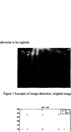
Figure 1 shows an example image of a calibration board on which dots are equally spaced. We can identify image distortion through displaced dots. Source of mage distortion consists oftwo major parts: lens and surround media. Effect of surround media is depicted as figure 2 . This figure demonstrates the fact that 0-7803-8541 -1/04/520.00 82004 IEEE.
underwater is far-sighted
am
810 a01 bm bin bo, Figure I Example of image distortion: original imageCR
4
4 4
0.0007 -0.4602 5.8875 0.0012 0.9016 13.0059 -0.0008 0.1185 -6.5152 -0.0018 0.0272 -11.7107 0.0015 -0.1910 5.6253 0.0010 1.0548 9.0964 ID1 m . m - . 0 XIJ ,.I "' ,U 0 1% * -i )m xo m soFigure 2 Effect of surrounding medis on image distortion
am
ao,
Tu compcnrare for the image distortion. w e adopt rhe dual plane m.,dr.l proposed h) (ircmbsn [ I I ]
4
c,"
4
0.0006 -0.3626 4.4153
0.0005 1.0132 5.8813
-0.0010 0.1229 -3.0734
where (x, y , z) is coordinates of a arbitrary point target, (xi, yj) is coordinates ofthe corresponding image point, Mand N are the order of polynomial for xi and yi. respectively. In this paper, we select M=N=3.
Owing to the perspective effect, calibration coefficients ..a and b , must be functions ofrlf Here, we use polynomial forms.
bin bo1
where K=2 in this paper.
0.0010 -0.1242 4.7871
0.0010 1.0635 7.1424
By taking images of calibration board from more than three different distances, as shown in figure 3, non-linear algebraic equations will be derived fmm equation ( I ) and equation (2). Then solving the equations by using least-square algorithm, we obtain calibration coefficients for right and leff cameras as shown in table I and table 2, in case ofundenvater and dry conditions.
an0 a01 bca bio bor CR
4
4
4
0.0023 -0.7706 8.8642-
0.0 0 8 5 2.5059 -23.2657 0.0002 -0.0208 -0.6509 0.0014 -0.4257 0.0880 -0.0004 0.0370 -1.7612 -0.0068 2.3952 -16.68101
bmI
-0.0018) 0.02361 -11.06361 -2160.0024 -0.6478 9.2164 -0.0075 -0.0010 0.1308 -2.9388 bw blo bo, 0.0007 -0.3473 -1.7444
.
-0.0017 0.2112 -5.7911 -0.0020 1.8347 -2.5880Althdugh calibration coefficients for underwater and dry conditions are different, the image of control points on calibration board aRer compensation will be almost the same as shown in figure 4.
:F1
. *
. .
*
. . . - .
-.. " ~ . . . .
Figure 4 Len and right images of control points afler compensationB.
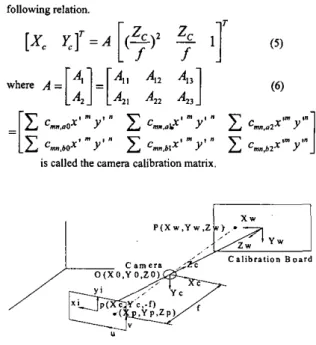
Camera Position and Orientation (figure 5)Considering a target point P whose coordinates are (X, Y, 2 , ) and (X, Y , Z,) in the world coordinates system and camera coordinates system, respectively. If the coordinates of camera center in the world coordinates system is &Yo, ZJ, then
following relation.
Figure 5 Calculation of Camera position and Orientation Equation (3) and equation ( 5 ) are fundamentals ofbundle
where (Xw, U,, &) denotes the position of camera center in the world coordinates system.
By using iterative least square algorithm, the camera position (Xw, Y,, &) and orientation (a,
p,
y) can be solved fromequation (7).
For verification, a rotation with respect to y-axis
(p)
test in five degree increment was conducted. Results are shown as table 3. The accuracy of the proposed algorithm is acceptable.On the other hand, from equation (I) and equation (2). we obtain the
I
z dcalibration
b-)
Figure
6
Configuration
for
camera
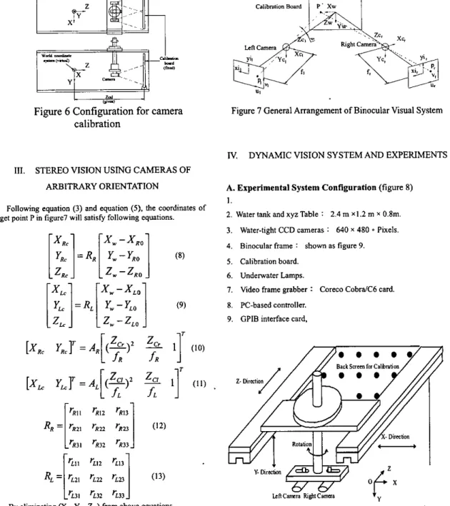
111. STEREO VISION
USING
CAMERAS OFARBITRARY ORIENTATION
Following equation (3) and equation (S), the coordinates of target point Pin figure7 will satisfy following equations.
Xw-XRo
[:!
I=
RR[:
]
[
1::
‘RI2 ‘Rt3] RR = ‘E21 ‘R22 ‘Rl3 (I2) ‘R32 ‘R33 ‘L32 ‘L33By eliminating (X, Y,
L)
from above equations, non-linear equations in terms of unknowns ( zC,, Z , ) will be obtained.Figure 7 General Arrangement of Binocular Visual System
IV. DYNAMIC VISION SYSTEM AND EXPERIMENTS
A. Experimental System Configuration (figure 8) 1.
2. Water tank and xyz Table : 2.4 m X I .2 m x 0.8m. 3. Water-tight CCD cameras : 640 x 480 0 Pixels.
4. Binocular frame : shown as figure 9. 5 . Calibration board.
6. Undenvater Lamps.
7. Video frame grabber : Coreco CobraiC6 card. 8. PC-based controller.
9. GPlB interface card,
Back Snrm for Calbrr
mcmra
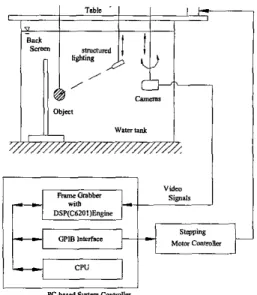
fi&tcam=aFigure 8 System Configureuration of Sensing and Perception Module Development Platform
Figure 9 Binocular frame
B. Tracking
.
System setup is shown as figure 10. A fish-shaped object was moved along a predetermined 3D path. According to the position and speed of object, the binocular vision system adaptively followed. The degree of freedom was three: bacwforth, upldown and horizontal rotation.Image sequence is shown as figure 11. During tracking, the system identified the object based on pattern matching technique.
We summarize the results of object tracking and motion trajectory estimation in figure 12. The estimated path matches well with the actual one.
F i m e
IO
Sketch of Underwater Active Stereo Vision Svstem(a) image pair at position 0
@) image pair at position 1
(c) image pair at positim 2
@image pair at position 7 Figure 11 Image Sequence
BW -.3w
2 "I XI")
Figure 12 Object Tracking and Motion Trajectory Estimation
C.
Mapping Using Active Laser BeamIn
stereo vision, match points searching task requires high computing power To ease hardware and software burden, we utilized active illumination method [IO] and tbresholding of image grayscale level. As a result, the range data acquisition nearly synchronized with frame acquisition.Example of surface mapping is shown in figure 13. The white spots of laser beam can be easily located.
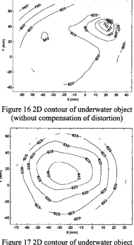
By mechanical scanning of laser point beam, we get the surface contour in 3D format shown as figure 14 and figure 15. Figure 16 and figure 17 are
of
2Dcontour format.Comparing figure14 with figure 15, and figure 16 with 17, it is clear that compensation of image distortion is essential to get accurate results.
(a)
(b)
Figure 13 (a)left image; (b) right image.
... ... ... ... . .. . bo ... :... ... . . .. . . . . . . . . . . . . . . . .. . . . . . . . . . ... .. .. . ... ~ : , . . .
Figure 14 3D contour
of
underwater object
(without compensation of distortion)
.:I
,;
, , ,r
,I
4bo -50 4 3(1 -2c -IO 0 10 m Jo 40
X("1
Figure
16 2D
contour of underwater object
(without compensation of distortion)
I
.
.
, , , I , ,.
, ,-70 bo €0 4 0 30 -20 -10 0 10 20 30
X("l
Figure
17
2D contour of underwater object
(distortion compensated)
Figure
15
3D contour
of
underwater object
(distortion compensated)
V. CONCLUSION
We demonstrated that the proposed method achieves better flexibility and accuracy compared to traditional underwater stereo vision methods.
ACKNOWLEDGMENT
The authors would like to thank the support from National Science Council of Republic of China (Taiwan).
[I21 C. Stiller and J. Konrad ,”Estimating Motion in Image Sequences,” IEEE Signal Processing Magazine, pp. 1053-5888, 1998.
REFERENCES
[I] Gmsso E. and Tistarelli M., “Active/Dynamic Stereo Vision,” Pattem Analysis and Machine Intelligence, IEEE Transactions on, Vo1.17, No. 9, pp. 868 -879, 1995. Grosso E. and Tislarelli M., “ActiveiDynamic Stereo: a General Framework,” Computer Viiion and Pottern Recognition Proceedings CVPR ‘9% 1993 IEEE Computer Sociery Conference on, pp. 732 -734, 1993.
Inaba, M. and Hara, T., “A Stereo Viewer Based on a Single Camera with View-Conlml Mechanisms,” Proceedings of the 1993 IEEERSJ lntemational Conference on Intelligent Robots and Systems, IROS’93, Vol. 3, pp. 1857-1865, 1993. Kougeaux S. and Kita N., “Binocular Tracking Based on Virtual Horopten,” Proceedings of the IEEEIRSJIGI International Conference on Intelligent Robots and Systems, IROS ‘94, Vol. 3, pp. 2052 -2057, 1994.
A. Goshtasby and W. A. Gruver, “Design of a Single-Lens Stereo Camera System,” Panern Recognition, Vol. 26, No. 6, pp. 923-937, 1993.
[2]
[3]
(41
[SI
[6] Sheng-Wen Cheng, Huai-Wen Hsu and Ling-Hao Yu, “Research on A Real-time Robotic Visual System for Ranging and Motion Estimation of Underwater Objects,” Proceedings of the 4Ih Conference on Underwater Science and Technology (CUST’OZ), pp.CI-19-27, Taipei, Taiwan, April 2002. Sheng-Wen Cheng, Huai-Wen Hsu and Chun-Fu Chang, “Development of a Dynamic Vision System for Tracking and Localization of Underwater Moving Objects,” Proceedings of the 5Ih Conference on Underwater Science and Technology (CUST’O3), pp.68-75, Kao-Hsiung, Taiwan, April 2003. S.I. Granshaw, “Bundle adjushnent methods in engineering photogrammetry,” Photogrametric Record, Vol. IO, No, 56, pp. 181-207, 1980.
KB.
Atkinson, Close Range Photogrammetry and MachineVision, Whittles Publishing, Caithness, Scotland, 1996.
[IO] R. Harlley and P. Sturm, ‘Triangulation,” Computer Vision and Image Understanding, Va1.68, No.2. pp. 146-157, 1997. [ I l l Gremban, K. D. and C. E. Thowe, “Geometric Camera
Calibration Using System of Linear Equation”, Proceedings o/ IEEE Internotionol Conference on Robotics and Automotion, pp. 562-567, 1988 [7] [8] [9] ’ -222.