Study on the Compound Effects of Interceptor with Stern Flap
for Two Fast Monohulls
J.
F.
Tsai, ProfessorNnr
J.L.
Hwang, Vice President USDDCDepartment of Engineering Science and Ocean Engineering, National Taiwan University No.1, Sec. 4, Roosevelt Road, Taipei, Taiwan, R.O.C.
United Ship Design and Development Center
14F, 27 Sec. 2, Chung-cheng E. Road, Tamshui, Taipei, Taiwan R.O.C. jftsai@ntu.edu.tw ilhwana@mail.usddc.orq.W
Abstract
-
The effect of trim mechanisms (including stern flap, interceptor and integrated interceptor with stern flap) on resistance reduction were examined in this study. Two planing crafts were used for the resistance test. The first one is a 20-meter patrol boat and the test was conducted at the towing tank of National Taiwan University(NTU), Taiwan, ROC. The seond one is 29.5-meter patrol boat tested at HSVA towing tank, The Hamburg Ship Model Basin, Germany. The results show that a welldesigned trim mechanism can reduce the running trim and the resistance of the planing craft. It also show that the trim mechanisms have a best resistance reduction effect at the volume Froude number between 2.0 and 2.5. The drag reduction of integrated interceptor with stern flap is better than that of interceptor alone and stern flap alone.I. INTRODUCTION
The planning crafl has a resistance hump located at the Froude number between 0.4 and 0.5. A bare planing craff needs a positive running trim to liff the hull and to overcome the resistance hump. In general, the optimum running trim is about 4 degrees for a bare planing crafl[l]. However, some research [2,3,4] showed that trim mechanisms, such as stern wedge, stern flap and interceptor, could reduce the running trim and the drag at the design speed. Karafiath and Fisher [2] showed that the stem wedge could reduce 0.4 to 2.0 degrees of running trim and a 2% saving of the fuel consumption at design speed. In recent years, the stern flap has been retrofit on large combatant-sized U.S. Navy vessels [5,6]. The performance benefits of decreased ship
power, leading directly to reduced fuel consumption, reduced emissions, and increased speed and range, have been proven from full-scale trials. Tsai and Huang
[7,8]
showed that the interceptor could effectively reduce the running trim and decrease the resistance of a planing hull. Most recently, Cusanelli and Karatiath [6,9] showed that the integrated wedge-flap could reduce the powering requirements compared to wedge only.
The trim mechanisms have proven themselves on the performance of drag reduction. The integrated wedge-flap configuration also has better performance than wedge only. In this study, the interceptor, stern flap and integrated interceptor-stem flap will be designed for two high speed planing crafis. The resistance tests will be conducted to examine the performance of the designed trim mechanisms.
II. THE 20M PATROL BOAT NTU MODEL The first planning patrol boat is 20m in length and 4.1m in breadth with a drafl of 0.92m. The displacement is 32.1 tons and the designed speed is 40 knots. Fig.1 shows the geometry of the patrol boat.
A FRP bare hull model, which is called NTU model thereafier, was manufactured with a scale ratio of IRO. The resistance tests were conducted at the towing tank of Department of Engineering Science and Ocean Engineering, National Taiwan University. The dimensions of the NTU towing tank are 130mXEmX4m. and the maximum speed of the towing carriage is 5 m/s. The experimental set up is shown in Fig.2. The measuring system includes a force gage, a trim gage and a potentiometer for heave motion at centre of gravity of the boat. The 95% confidence interval of the force gage is 0.014Kg, the trim gage is 0.2 degrees, and the potentiometer is 0.2cm.
. . . - . . . ___.
.
. .....
- - ~. ... . ...
Fig.1. Geometry of the 20m patrol boat tested at NTU
The resistance test results ofthe bare hull model are shown in Fig.3. The figure shows the resistance coefficient Ct,, running trim and heave with volume Froude number Fn
.
The resistance coefficient Ctm and the volume Froude number are defined as:V
F"
-
JF
Where Rt, is the total measured resistance of the model, V is the speed of the craf? model; S is the wetted surface of the model and
In Fig.3. it is found that the resistance hump occurs at Fn =1.1 which is located at the maximum negative heave motion (The maximum loss of buoyancy). The running trim at design speed 40 knots (Fn =3.638) is 4 degrees. As Fn >2.5. the running trim decreases.
The height of interceptor was estimated by using boundary momentum thickness developed by Tsai and Huang[7j. The estimated height is about lmm for the NTU model. The resistance test with three interceptors of height O.5mm, 1.0" and 1.5" were conducted to seek the optimum interceptor height. Fig.4 shows the resistanceldisplacement coefficient of the NTU model with three different interceptors. Fig.5 shows the drag reduction effect compared to the bare test result. The l m m interceptor has better drag reduction effect as Fn
<=3.0.
The 18%maximum drag reduction occurred at Fn =2.4 . The drag reduction effect of 0.5mm interceptor is better than that of 1.0" when volume Froude number is greater than 3.0. There is 10% drag reduction at design speed. Fig.6 shows the effect of interceptor on running trim. The over designed height of interceptor causes a trim by bow situation which increases the drag of the boat.
is the displacement volume.
0.0
-I
-2.00.5 1.0 1.5 2.0 2.5 3.0 3.5 4.0 F"V
Fig.3. Resistance test results of Bare NTU model
B
O.m
-
0.50 1.00 1.50 2.00 2.50 3.00 3.50
VolumeFroudeNumber ,.F
x)
Fig.4. Resistance test results for three interceptors
1.20
-"I
""I
0 . a
-
0.50 1.00 1.50 2.00 2.50 3.00 3.50
Volume Froude Number Fnv
Fig.5. Drag reduction effect of interceptors
7.00
comporkon orRunning ~~i~ ror intercepton hOO
-
4 I=O.O" 4 1-0.5mm 1- 1.0" 5.00-
I=Q
400- Eb
3.00-.c
E
' 0 0 -d
-. 1.00-
0.00-
-1.00 I I I I I I 0.50 l o o 1.50 2 0 0 2 5 0 3.00 3.50 8 VolumoFroudeNumber FnvFig.6. Running trims of interceptors
Three stern flaps with different trailing edge down angles, including 4, 8, and 12 degrees, were installed on the transom of the NTU model to conduct resistance tests. The chord length of three stern flaps is 2.5% of ship length. The span is halfthe breadth ofthe transom plus the chord length of the stern flap. Fig.7 shows the effect of stern flaps on the resistanceldisplacement coefficient. Fig.8 shows the drag reduction of the stern flaps. The results show that the 8 degree stern flap can reduce 1.2 degree running trim and have a 6% drag reduction at the design speed. The 20% maximum drag reduction also occurred at Fn =2.4. Fig.9 shows the test results of running trim for the three stern flaps.
Fig.10 shows the schematic drawing of the combination of the integrated interceptor and stern flap. In order to find the optimum combination of the integrated interceptor and stern flap, the resistance tests of six combinations of the integrated interceptor of 0.5" and l.Omm with stern flap of 4, 8 and 12 degrees were conducted. Fig.11 shows the drag reduction of the 0.5 mm interceptor integrated with the three stern flaps. Fig.12 shows the drag reduction of the 1.0 mm interceptor integrated with the three stem flaps.
2.40
.
2.20-
2.00-
1.80-
1.60-
g
1.40-5
130-5
1.00-
a 0.RO-
Comparison orRpsistnnce displrcm" Rnso
-
s=0 -f s = 4 --I-- S = R --c. S I 2 far Stem F l o p 0.50 1.00 1.50 2.00 2.50 3.00 3.50 4.00Volume Froude Number Fnv
Fig.7. Resistance test results of stern flaps
It is found that the drag reduction of the 0.5 mm interceptor integrated with 4-degree stern flap is the best one. It has 21% maximum drag reduction at Fn =2.55 and 12% drag reduction at design speed 40 knots.
6 0 0
-
5 0 0-
400-
1 0 0 - i.;
2.00-
d
I 1.00-
0.00 -$ -1.00 0.50 1.W 1.B 2.00 2 5 0 3.03 350 Volume Froude N m b e r FovFig.9. Running trims of stern flaps
I0
Fig.10. Schematic drawing of the integrated interceptor and stern flap.
0.50 1.00 1.50 2.00 2.50 3.00 3.50 4.00 Volvmo RoudeNumberFno
Fig.8. Drag reduction effect of stern flaps
0.60
-
0.50 1.00 1.50 2.W 2.50 3.00 3.50 4.00
Volume Froude Number Fnv
Fig.11. Drag reduction effect of the 0 . 5 " intercept01 integrated with three stern flaps.
1.4 1.20 1.00
a
0.80 0.60 Full(d=1.700m) I I I I I I 1.00 1.50 2.00 250 3.00 3.50 z V o l v m ~ FPoude Number Fnv4 deg. Stern Flap 1.307
Fig.12. Drag reduction effect of the l.Omm interceptor
integrated with three stern flaps. 1.6 -
1.2 -
d
3
0.4
-
Ill. THE 30M PATROL BOAT HSVA MODEL The second planning boat is 29.5 m in length and 6.628m in breadth with draft of 1.7m. The displacement is 145 tons. The design speed is 32 knots. The 1/10 bare hull wooden model was manufactured by HSVA (The Hamberg Ship Model Basin, Germany). Fig.13 shows the body plan of the patrol boat. The resistance tests were done at the HSVA towing tank. [lo, 111. The tests were conducted following the standard procedure at of HSVA towing tank.
The optimum height of the interceptor was determined from the comparison of resistance test results at the trial speed 30 knots of the trial condition only
.
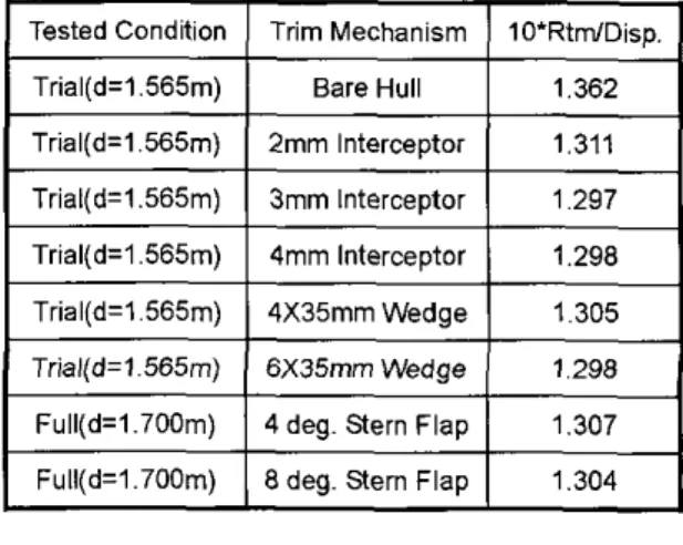
The evaluated heights were Omm, 2mm, 3mm and 4mm. Two trim wedges of 4mm height and 6 mm height with 35 mm length were also included. The test results are shown in Table.1. The 3mm interceptor was selected as the height of the integrated interceptor with stern flap.
The evaluated angles of the stern flap were 0,
4
and8
degrees. The tested results are shown in Fig.14 and Fig.15. At the design speed, the effective power of full scale for all test conditions are shown in table 2. The test results show that the integrated 3mm interceptor and 8 degrees stem flap delivers superior resistance performance.
Table 1: HSVATest results oftrim mechanisms
1.311 1.297 1.298
P
0.0 0 5 1.0 1.5 2 0 2.5 F"0Fig.14. Resistance tested results of 3mm interceptor with stern flaps.
+
ISF[X4) 2.0-
.@
1.0 c 0.5 - 0.0-
4.5,
0.5 1.0 1.5 Z O 2.5 F"0 IFig.15. Running trims of 3mm interceptorwith stern flaps Fig.13. Geometry of 145 tons patrol boattested at HSVA
Stem Flap Angle 8 0 177 2919 Interceptor RT(lrN) PE(kW) Height(") 4 ~~~ ~~ ~~
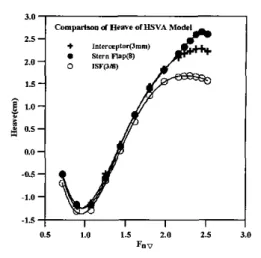
The comparisons of the effect of interceptor, stern flap and interated interceptor with stern flap on the resistance performance of HSVA model are shown in Fig.16. Fig.17 shows the results of running trim. Fig.18 shows the results of heave. The integrated interceptor with stern flap configuration has the minimum resistanceldisplacement coefficient as shown in Fig.16 and Table 3. The running trim and heave ofthese three configurations at design speed are shown in Table 4. The integrated interceptor with stern flap configuration has the minimum value of running trim and heave at design speed also.
3 173 2855
8
0.0
0.5 1.0 1.5 2.0 2.5
h V
Fig.16. Comparison of resistanceldisplacement coefficient of HSVA model for different trim mechanisms
3 172 2824 2.0
-
P;
1.5-4
e
1.0- k 0.5-
0.0-
1.8-
1.6- 1.1 -*
1.2 -e
1.0-s
1'
0.8- 0.6- 0.4 - 0.2-
a 5 1.0 1.5 LO 2.5 3.0 F. vFig.17. Comparison of running trim of HSVA model for different trim mechanisms
Configurations Running Trim (Degree) 3mm Interceptor 1.367 8 Deg. Stern Flap 1.783 ISF(3/8) 0.650
0.5 1.0 1.5 2.0 2.5 3.0
F. v
Fig.16. Comparison of heave of HSVA model for different trim mechanisms
Table 3. The ResistancelDisplacement coefficient of HSVA Mode for different trim mechanisms
Heave(cm)
2.23 2.46 1.68
IV. CONCLUSIONS
The following conclusions can be drawn from the test results:
1. A well-designed trim mechanism, such as interceptor, stern flap and integrated interceptor and stern flap, can reduce the running trim and decrease the resistance of the planning crafk
2. The optimum trim mechanism of the NTU model is the integrated 0.5" interceptor with 4 degrees stern flap. The 21% drag reduction is obtained in this Configuration at Fn =2.55 and 12% drag reduction at design speed 40 knots.
3. The optimum trim mechanism of the HSVA model is also the integrated configuration made of a 3mm interceptor and 8 degrees stem flap.
4. The maximum drag reduction by the trim mechanisms occurred at the range of the volume Froude number
5. The running trim of bare hull is about 4 degrees. The running trim of planning craff with trim mechanism could be reduced to about 1 degree to 2 degrees.
The optimum height of the interceptor and the angle of the stern flap were determined from the tests performed. The accuracy of the optimum values is limited due to the limited tests conducted. To develop a numerical method and an empirical method to predict the optimum value are encouraged.
V. ACKNOWLEDGMENTS
The authors would like to thank to the National Science Council of Taiwan, R.O.C. (NSC93-25164-002-001) and the Ministry of Economy, ROC for their financial support of this research.
VI. REFERENCES
1. D. Savitsky, 'Planing Craw, Naval Engineers Journal, Feb., 1985.
2. G. Karafiath, and S.C. Fisher, 'The effect of Stern Wedges on Ship Powering Performance', Naval Engineers Journal, May, 1987.
3. CT. Wang, 'Wedge Effect on Planning Hulls', J. Hydronautics, Vo1.14, No.4, 1980.
4. J.F. Tsai, J.L. Hwang, S.W. Chau, and S.K. Chou, 'Study of Hydrofoil Assistance Arrangement for Catamaran with Stern Flap and Interceptor', FAST 2001, Southampton, UK, Sep., 2001.
5. D.S. Cusanelli, and W.L. Cave, 'Effect of Stern Flaps on Dowerincl Performance of the FFG-7 Class'. Marine Technology~Vo1.30, No.1, Jan., 1993.
6. D.S. Cusanelli, and G. Karafiath, 'Advances in Stern Flap Design and application', FAST 2001, Southampton, UK, . . Sep.,
2001.
7. J.F. Tsai, and J.K. Huang, 'Study on the Effect of lntercedor on high Speed craff, Journal of the Society of Naval Architects and Marine Engineers, ROC, V01.22, No. 2, 2003, pp.95-101
8. J.F. Tsai, J. L. Hwang, S.W. Chau, and S.K. Chou," Study on the Compound Effects of Interceptor with Stern Flap for Two Fast Monohulls with Transom. Stern", FAST2003, Italy. 2003.
9. D.S. Cusanelli, and G. Karafiath, 'Integrated Wedge Flap for Enhanced Powering Performance', FAST'97, Sidney, Australia, July, 1997.
10. HSVA, 'Resistance Tests for a New 100 Tons Patrol Boat', HSVA Report WP 57/02,2002.
11. HSVA, 'Resistance Tests for a New 100 Tons Patrol Boat', HSVA Report WP 65/02,2002.